Article

In Situ Production of Titanium Aluminides during Wire Arc Additive Manufacturing with Hot-Wire Assisted GMAW Process

Production Technology Group, Technische Universität Ilmenau, D-98693 Ilmenau, Germany
*
Author to whom correspondence should be addressed.
Metals 2019, 9(5), 578; https://doi.org/10.3390/met9050578
Submission received: 23 April 2019 / Revised: 15 May 2019 / Accepted: 16 May 2019 / Published: 18 May 2019
(This article belongs to the Special Issue Arc-based Additive Manufacturing)

Abstract

:
As part of a feasibility study, an alternative production process for titanium aluminides was investigated. This process is based on in situ alloying by means of a multi-wire technique in the layer-wise additive manufacturing process. Thereby, gas metal arc welding (GMAW) was combined with additional hot-wire feeding. By using two separate wires made of titanium and aluminum, it is possible to implement the alloy formation of titanium aluminides directly in the weld bead of the welding process. In this study, wall structures were built layer-by-layer with alloy compositions between 10 at% and 55 at% aluminum by changing the feeding rates. During this investigation, the macroscopic characteristics, microstructural formation, and the change of the microhardness values were analyzed. A close examination of the influence of welding speed and post-process heat treatment on the Ti–47Al alloy was performed; this being particularly relevant due to its economically wide spread applications.

1. Introduction

Titanium aluminides (Ti–Al) provide excellent material properties such as oxidation resistance at high temperatures, as well as high specific strength at a low density of 3.8 g/cm3. Therefore, industrial applications for mechanically and thermally highly stressed components can be addressed [1,2,3]. The material can be utilized in many different applications, such as turbine blades or compressor wheels in exhaust gas turbochargers in the latest generation of engines [4,5]. However, conventional production routes of titanium aluminides prevent extensive industrial use due to numerous steps in the production chain [3,4,6,7,8,9,10].
An alternative route for the production of Ti–Al parts can be described by additive manufacturing. Thereby, titanium and aluminum filler material can be merged into a common weld bead which leads to a dilution of the materials and in situ alloy formation. For conventional metal alloys, additive manufacturing (AM) by laser, electron beam, or arc welding processes are proven to be an economically viable alternative [11].
Since the 1990s many studies have been performed worldwide in terms of the manufacturing of components with arc processes. In these cases, gas metal arc welding (GMAW), gas tungsten arc welding (GTAW), and plasma arc welding (PTA) were analyzed. Thereby, various materials such as aluminum, steel, nickel, and titanium alloys (mainly Ti–6Al–4V) have been investigated with deposition rates of >1 kg/h [12,13,14,15].
So far, only a few studies have been conducted on the production of intermetallic phases such as Ti–Al. Therefore, laser and electron beam processes have been used almost exclusively with pre-alloyed, high-purity, gas-atomized Ti–Al powders [16,17,18,19]. Another approach was investigated by Gasper et al. [20] which involved processing filler wire via laser metal deposition (LMD). A material cost reduction of 40% could be achieved. Ma et al. [21] investigated the in situ alloying of titanium aluminides during wire arc additive manufacturing (WAAM) using the tungsten inert gas (TIG) welding process. Hereby, wall structures were built while both titanium and aluminum wires were fed into the arc using a common weld bead. In this research, the influence of process parameters on microstructure and mechanical properties was tested on titanium aluminide with 44 at% aluminum.
Thus far, no scientific paper has been published concerning the use of a hot-wire assisted GMAW process using titanium and aluminum wire for in situ alloying of Ti–Al with adapted metallurgical properties and differing phases. This refers to the process management, as well as the process limits and resulting material properties of the additively manufactured structures. Thereby, a reduced experimental setup can be used compared to investigations with TIG process.

2. Scope of the Investigations

The objective of the study was the in situ production of titanium aluminides during wire arc additive manufacturing with hot-wire assisted GMAW. Herein, wire feeding rates of titanium and aluminum were systematically varied to generate structures with adapted metallurgical properties additively. In this case, the microstructural formation of alloys with aluminum contents of 10 at% to 55 at% was investigated and the change of microstructure was demonstrated. The analysis of Ti–47Al is of high interest due to its numerous industrial applications as mentioned before. Therefore, the macroscopic features, microstructure, and material hardness of a Ti–47Al were investigated by means of varied welding speeds and post-process heat treatment.

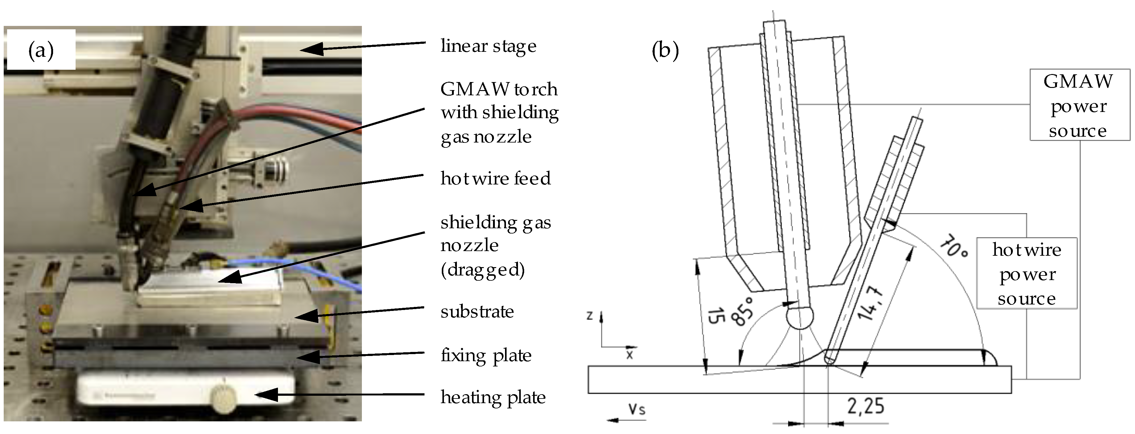
3. Materials and Methods

Additive manufacturing was conducted with a hot-wire assisted GMAW process. Therefore, a welding power source of the type Alpha Q 551 Puls (EWM AG, Mündersbach, Germany) and a water-cooled welding torch AMT551W (EWM AG, Mündersbach, Germany) were used. The reproducible guidance of the welding torch was realized using a linear drive LES4 and a two-phase step motor MS200 HT (isel Germany AG, Eichenzell, Germany), which were controlled by a—controller IT116 Flash (isel Germany AG, Eichenzell, Germany). An EWM Triton 260 TGD power source was modified by Dinse (Dinse GmbH, Hamburg, Germany) in order to be applied to the hot-wire process. The GMAW process was conducted with a pulsed arc. The heating of the hot wire was realized by resistance heating via direct current. The experimental setup (a) and schematic setup (b) is shown in Figure 1.
Measurement data were acquired by a Dewetron DEWE-PCI 16 measuring system (version DEWE-800, Dewetron GmbH, Grambach, Austria) with integrated software (Dewesoft 7.1.1, DEWESoft Deutschland GmbH, Unterensingen, Germany) and measuring cards to record current, voltage, and inter-pass temperature. Here, a jacket thermocouple of type K with a diameter of 1 mm was used. The generated wall structures were separated from the substrate by wire-electro discharge machining (EDM). Afterwards the samples were prepared for metallographic analysis including grinding and polishing. The etching was examined with Kroll solution based on 6% nitric acid and 3% hydrofluoric acid. Furthermore, XRD analysis was performed to determine the existing phases using an X-ray diffractometer Siemens D5000 (Siemens AG, Munich, Germany) with theta-2 Theta arrangement. A vanadium filter with a span over 2θ between 50° and 162° with 0.04° steps was used. The measurements were performed with an acceleration voltage of 35 kV and a current of 50 mA. The microhardness measurements were tested on a DuraScan 70 machine (Struers GmbH, Willich, Germany) using the Vickers testing method according to DIN EN ISO 6507-1 with a force of 1.961 N (HV0.2). Post-heat treatment was examined with a temperature of 1180 °C under atmospheric conditions for a period of 4 h, 8 h, and 12 h. The samples were cooled down to room temperature by air cooling.
In this research, titanium grade 2 (3.7035) was used as substrate material with a thickness of 10 mm. Solid wires were used as filler materials. Therefore, titanium wire (Ti99.6, 3.7036, Ø = 1.0 mm) was processed as melting electrode in the GMAW process and aluminum wire (Al99.5Ti, 3.0805, Ø = 1.0 mm) was applied by hot-wire feeding. Table 1 shows the chemical composition of the substrate material and filler wires.
During WAAM, argon 4.6 was used as shielding gas for the GMAW process. Additionally, a dragged shielding gas nozzle (see Figure 1) was installed to prevent the manufactured structures from absorbing atmospheric gases. In order to adjust the material composition, the hot-wire feeding rate was adapted systematically. As a result of the denomination of alloying elements and phase diagrams based on atomic percent (at%), it was necessary to calculate the desired material composition in weight percent (wt%). Equation (1) (according to [22]) is as follows, where M1, M2 describe the molar mass of Ti and Al in (g/mol), at%1, at%2 describe the atomic percentage of Ti and Al in (%), and ωx describes the degree of purity of each wire in (%). An alloying content of 0.15% Ti in the aluminum wire is considered to be sufficient.
w t % x = a t % 1 M 1 a t % 1 M 1 + a t % 2 M 2 ω x .
The conversion from mass to volume percent is described in Equation (2) according to [22]. Herein, ρ1, ρ2 describe the density of titanium and aluminum in (g/cm3).
v o l % = w t % 1 ρ 2 w t % 1 ρ 2 + w t % 2 ρ 1 .
The adjustment of the material composition is based on the principle of mass conservation. The following equation of continuity for stationary volumetric flow is applied Equation (3). This is described by the product of velocity v in (m/s) and cross sectional area A in (m2) of the medium.
V ˙ = v A .
The volumetric flow of the applied materials titanium Equation (4) and aluminum Equation (5) is derived from Equation (3). Herein, v1 and v2 describe the wire feeding rates in [m/min], whereas d1, d2 describe the diameter of the wires in (mm).
V 1 ˙ = v o l % 1 Δ t = v 1 π 4 d 1 2 v 1 π 4 d 1 2 + v 2 π 4 d 2 2 100 % ,
V 2 ˙ = v o l % 2 Δ t = v 2 π 4 d 2 2 v 2 π 4 d 2 2 + v 1 π 4 d 1 2 100 % .
Equation (6) describes the wire feed ratio fratio of aluminum and titanium wire based on Equations (1) to (5).
f r a t i o = v 1 v 2 = v o l % 1 d 2 2 v o l % 2 d 1 2 .
With a fixed feeding rate of the titanium wire, the feeding rate of the aluminum wire can be calculated by means of the wire feed ratio. For the experimental trials, the GMAW wire feeding rate was set to 4 m/min. Table 2 shows the resulting hot-wire feeding rates of the aluminum wire used to adjust the content of aluminum in the desired steps.

4. Results and Discussion

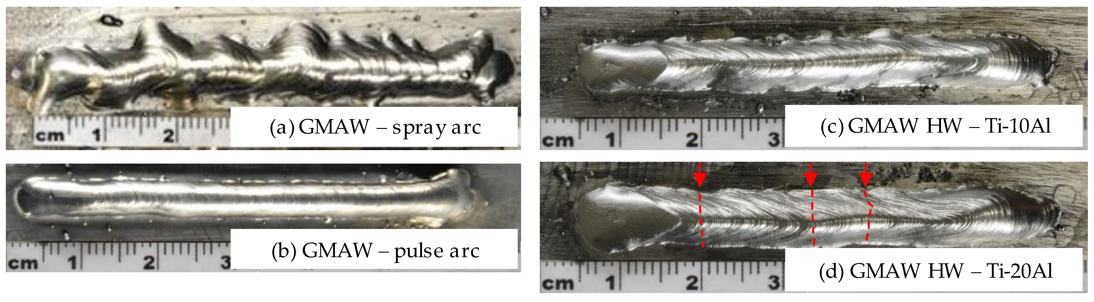
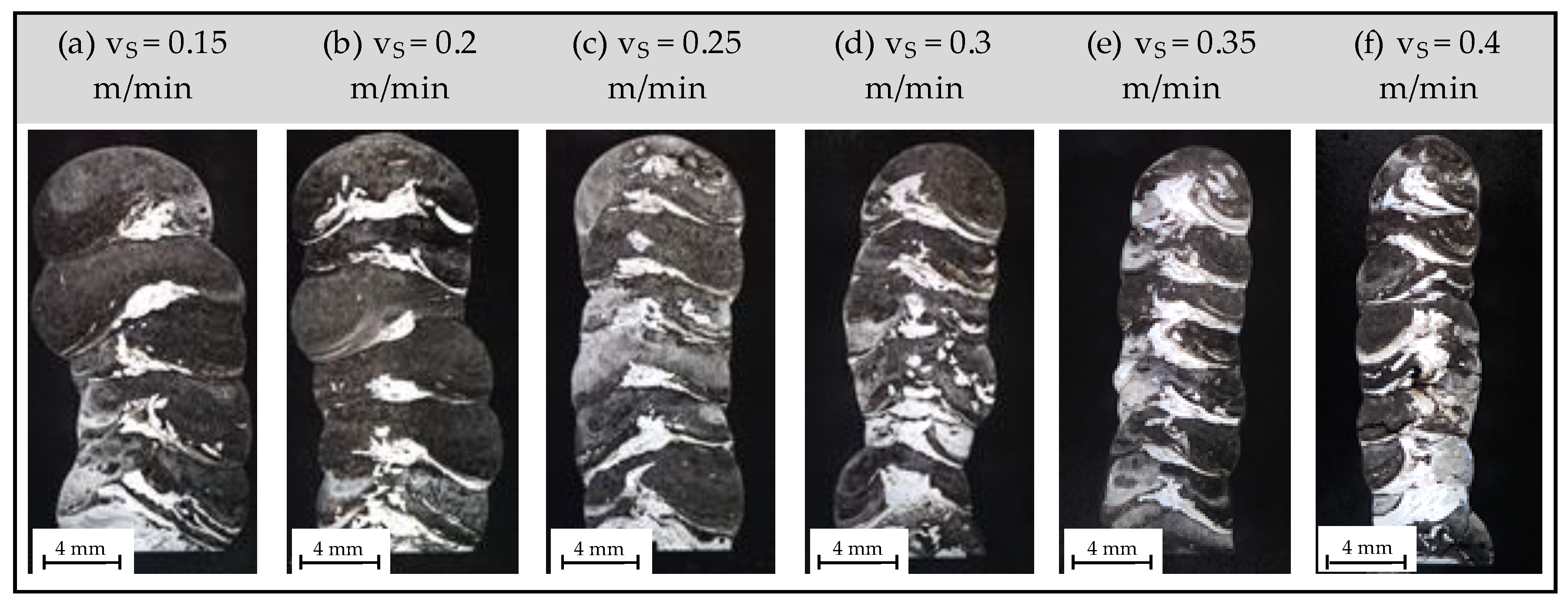
4.1. Preliminary Investigations on Process Behavior

Preliminary investigations on process behavior concerned with arc stability and geometrical properties of the resulting weld seams are as follows. In order to increase weld bead size and wetting behavior for an additional hot-wire process, investigations of the GMAW process with titanium wire were carried out in spray arc and pulse arc welding regimes. A wire feeding rate of 4 m/min, welding velocity of 0.2 m/min, and welding voltage of 27 V resulted in a short circuit free transfer of the melting electrode. The welding process was characterized by large volume droplets and a flickering arc resulting in an insufficient weld seam geometry (see Figure 2a). This is due to the high surface tension of liquid titanium and typical spot displacements in GMAW of Ti.
Moreover, GMAW processing was adapted to the pulse arc welding regime. Welding velocity, voltage, and wire feeding rates were kept constant. The pulse frequency was initially set to 120 Hz, resulting in large spatter formation. A continuous decrease in pulse frequency to 50 Hz resulted in reduced spatter formation. These results were also presented by Zhang and Li [23] for pulsed arc welding of titanium grade 1. A pulse frequency of f < 60 Hz resulted in insufficient weld seam geometry comparable to spray arc transfer (compare Figure 2a). As a result, the pulse frequency was set to 70 Hz in order to realize a spatter free material transfer of one droplet per pulse with sufficient bead geometry (compare Figure 2b).
In the next step, experimental trials with an additional hot wire (HW) were tested. Thereby, feeding rates for the aluminum wire were adapted according to Equations (1) to (6) in order to adapt the content of Al from 10 at% to 55 at% with a constant feeding rate of the Ti wire of 4 m/min. Figure 2c,d show the resulting weld seam geometries for aluminum contents of 10 at% and 20 at% in Ti–Al. The preheating of the hot wire was adjusted to 100 °C throughout the setting of the hot-wire current and additional temperature measurements on the extending aluminum wire. A homogeneous weld seam width and height can be seen for both aluminum concentrations. However, an increased percentage of Al ≥20% leads to the formation of cold cracks (compare Figure 2d, red arrows) in the weld seams. This can be explained by the formation of the brittle α2-phase with an increasing aluminum content above 12 at%.

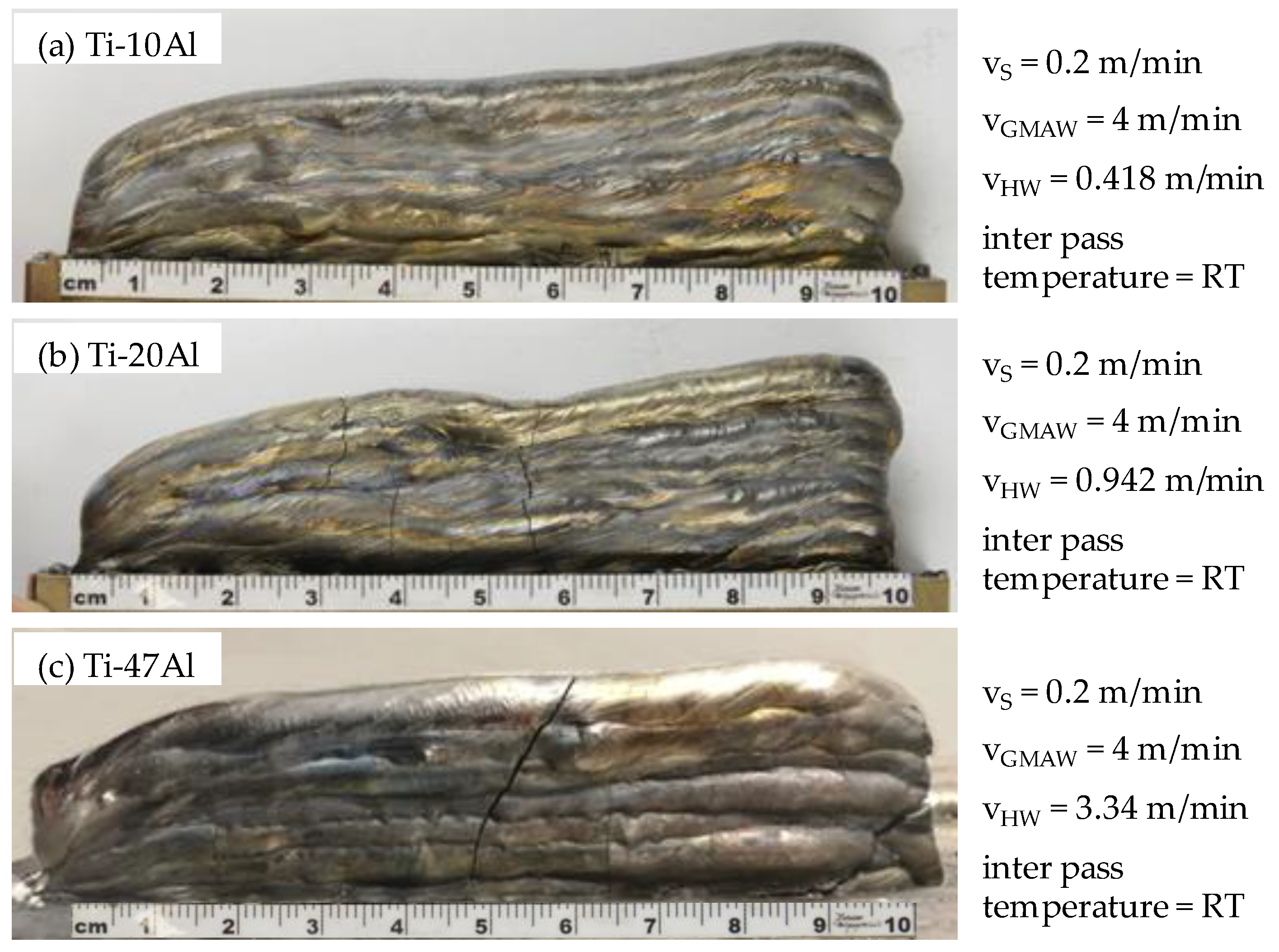
4.2. Wire Arc Additive Manufacturing of Ti–Al Structures with Al Concentrations of 10–55 at%

In the next step of the feasibility study, two-dimensional wall structures were additively built with the hot-wire assisted GMAW process. The movement of the welding torch was set in the same direction in each layer, resulting in an inhomogeneous structure height due to arc ignition and erasure at the same point. The inter-pass temperature was set to room temperature (RT).
Figure 3 shows exemplary Ti–Al samples with differing contents of aluminum. The wire feeding rates of the GMWA process vGMAW and additional hot-wire process vHW were set according to Table 2. Additionally, welding speed vs. and inter-pass temperature are stated.
Thereby, a crack-free structure of titanium aluminide alloy could be manufactured with an aluminum content of 10 at% (see Figure 3a). In contrast, the wall structure with an aluminum content of 20 at% shows initial cold cracks (see Figure 3b). These cracks form in the first layer during cooling and run transverse to the welding direction. With an increased structure height, the cracks extend throughout the set layers. The formation of cold cracks can be explained by the formation of the brittle α2-phase. The industrial relevant Ti–Al phase with 47 at% aluminum is shown in Figure 3c. Herein, the α2-phase is formed likewise, resulting in cold cracks.
The formation of cold cracks throughout the additively built work pieces can be described as weld defects resulting in limited applicability of the produced parts. A processing strategy for reducing the formation of cracks can be achieved by increasing the inter-pass temperatures. In addition, stress reduction in the weld seams can be achieved by reduced temperature gradients during cooling. However, this feasibility study is concerned with in situ alloying of titanium aluminides and constantly set inter-pass temperatures (IPT) at room temperature. Further investigations will need to focus on increased IPT.

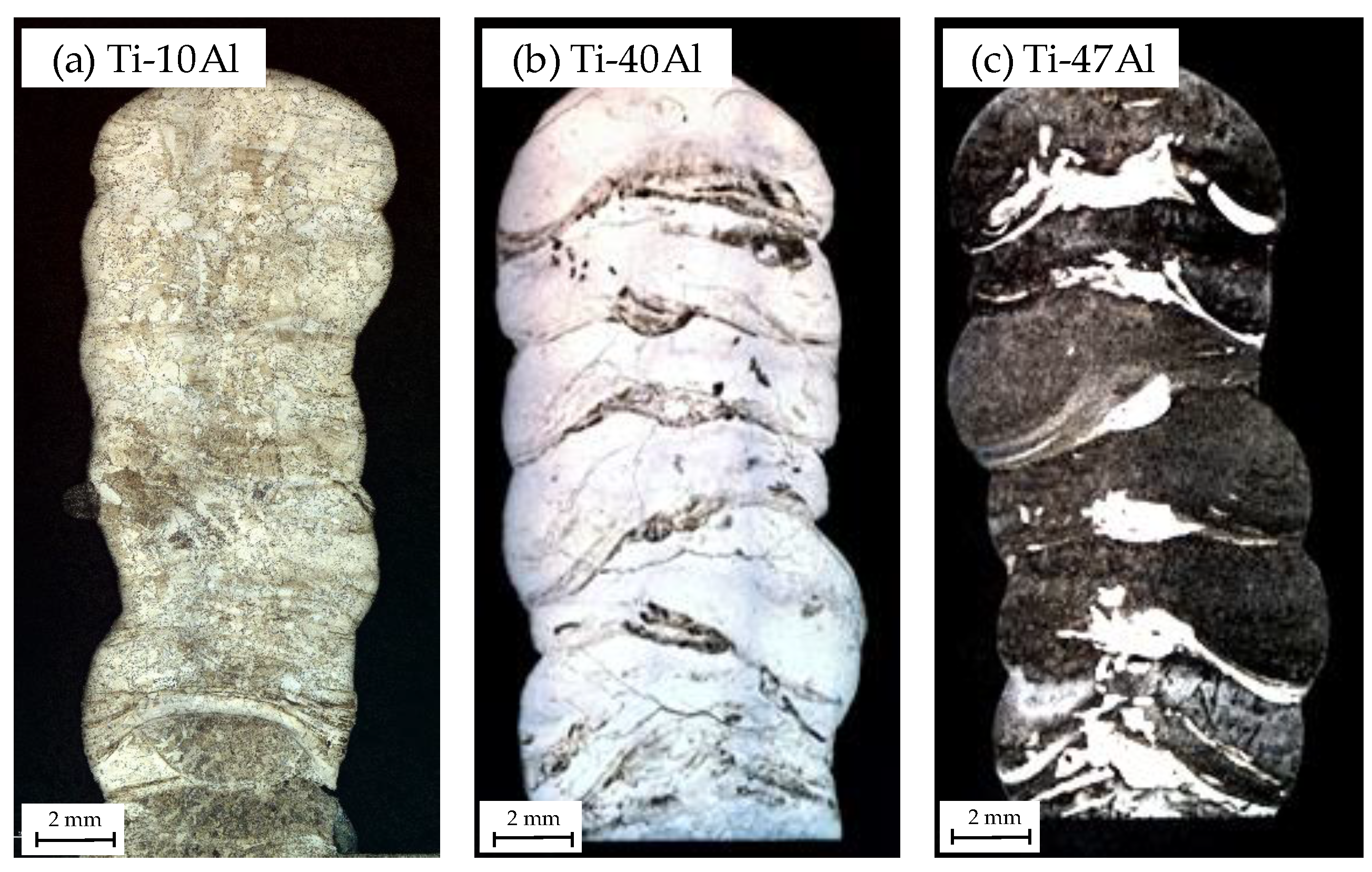
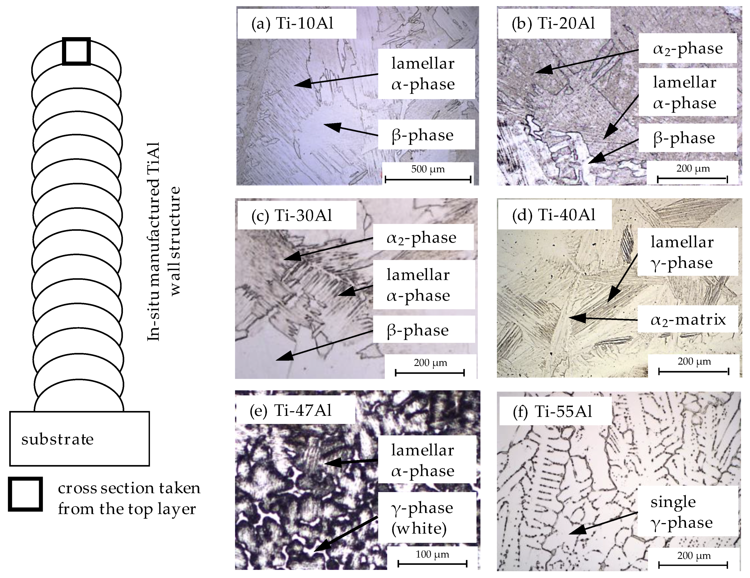
4.3. Microstructural Analysis of Ti–Al Samples

Appel et al. [24] investigated the Ti–Al system and identified intermetallic phases that are shown in a binary Ti–Al phase diagram. The industrial relevant single phases are Ti3Al (α2)- and TiAl (γ)-phase. Thereby, the α2–phase is characterized by a ductility of 2%–10% at room temperature. However, high absorption rates of oxygen and hydrogen lead to embrittlement at temperatures >550 °C [8]. The single TiAl (γ)-phase is characterized by oxidation resistance and high temperature resistance to the melting point of approximately 1450 °C [8]. In contrast, the ductility and fracture toughness of γ-phase TiAl are negligible. Therefore, single-phase titanium aluminides have only limited relevance for technical applications. Mainly, two-phased γ-TiAl (e.g., Ti–47Al) is characterized by desired mechanic and thermodynamic properties such as high temperature resistance (up to 1450 °C), oxidation resistance (up to 800 °C), and high tensile strength [8]. Further intermetallic phases of the Ti–Al system and their correlating aluminum contents can be seen in Table 3. Overlapping ranges of aluminum content are due to temperature dependent phase formation.
Figure 4a–c shows exemplary cross sections of titanium aluminide wall structures with aluminum contents of 10 at%, 40 at%, and 47 at%. Herein, Ti–10Al shows a homogeneous microstructure with interlayer grain growth. This can be explained by high, periodic heat input during WAAM leading to remelting of the set layers and grain growth across the single weld seams. However, during metallographic analysis, it was found that areas with insufficiently mixed Ti and Al contents occur in samples with aluminum contents above 40 at% (see Figure 4b,c). On the one hand, an explanation could be found in the welding process with hot-wire assisted pulse arc welding regime. An increasing hot-wire feeding rate has to be set for rising aluminum concentrations at a constant GMAW wire feeding rate. This leads to the formation of large volume weld beads. However, insufficient mixture of Ti and Al occurs throughout modified fluid flow in the melt.
On the other hand, an explanation could be found in the varying material properties of the used filler wires. The fed aluminum wire melts directly onto the surface of the titanium melt pool due to strongly varying melting temperatures. The low density of the aluminum then leads to an increasing Al content on the weld seam surface, whereas titanium is accumulated in the lower part of the weld seam leading to an insufficient mixture. As a result of the findings, cross sections of all Ti–Al compositions from 10 at% to 55 at% Al were analyzed in the center part of the top layer due to sufficient dilution of Ti and Al (see Figure 4c). Further imperfections of the additively built 2D structures (e.g., pores, lack of fusion, etc.) could not be detected in the cross sections.
Figure 5 shows cross sections of the stated Ti–Al compositions (see Table 2) with differing phase formation due to an increasing Al content. The microstructure of a titanium alloy with 10 at% aluminum is shown in Figure 5a. The typical structure of the β+α-phase can be shown to be similar to the Widmanstätten structure. Herein, β-grains form at the grain boundaries of lamellar α-colonies. Ti–20Al alloy (see Figure 5b) contains both areas of α2-phase fractions as well as β + α structures, which is identifiable because of the thin lath morphology inside the grains. A comparable microstructure can be seen in Ti–30Al alloy (see Figure 5c). Figure 5d shows the microstructure of Ti–40Al with 40 at% aluminum with α2-grains. In this matrix of the α2-phase, the formation of the γ-phase starts growing lamellar. The orientation of the γ-phase is uniaxial and periodic. With the increasing aluminum content, the proportion of the γ-phase increases as well. An aluminum content of 47 at% aluminum leads to a lamellar and two-phased α2 + γ structure. Typical dendritic formations and interdendritic spaces can be seen (see Figure 5e). The star shaped branches grow at an angle of about 60° with an embedded interdendritic γ-phase (white area). Further increased aluminum content leads to the γ-phase growing, until a single-phase γ-structure can be seen at 55 at% aluminum content (see Figure 5f). Further investigations on the microstructure were conducted by XRD analysis (Section 4.5) and hardness measurements (Section 4.6).

4.4. Approaches to Reduce Inhomogeneity of the Microstructural Composition

On the basis of Ti–47Al, a further approach was examined to reduce phase inhomogeneity. Therefore, the influence of welding speed was investigated (see Figure 6) in order to modify fluid flow and dilution of the materials in the melt. Starting from an initial welding speed of 0.2 m/min, the welding velocity was systematically varied in steps of 0.05 m/min. The minimum velocity was set to 0.15 m/min, whereas the maximum welding speed was increased to 0.4 m/min. The inter-pass temperature was set to RT.
It can be seen that welding speed and resulting structure width correlate directly. On one hand, increased welding speed results in reduced weld bead width due to reduced material deposition per time. On the other hand, the near net shape of the structures can be improved through a faster solidification of the set weld seams (see Figure 6f).
Furthermore, the variation of the process speed affects the microstructural composition of the structures. It can be seen that a welding speed of 0.4 m/min (see Figure 6f) results in high segregation of titanium (white areas) and aluminum (dark areas). An explanation could be found in the modified fluid flow in the melt pool or the faster solidification of the weld bead with the decreased period of time for volume diffusion of molten titanium and aluminum. In contrast, Figure 6a shows enhanced dilution of the two alloying components. The slower welding speed results in an enlarged melt pool volume with a decreased solidification rate of the melt. However, the risk of process abortion increases because of the large weld bead volume and the occurrence of melt flow in the set layers. Moreover, a degraded near net shape of the structures can be seen (see Figure 6a).

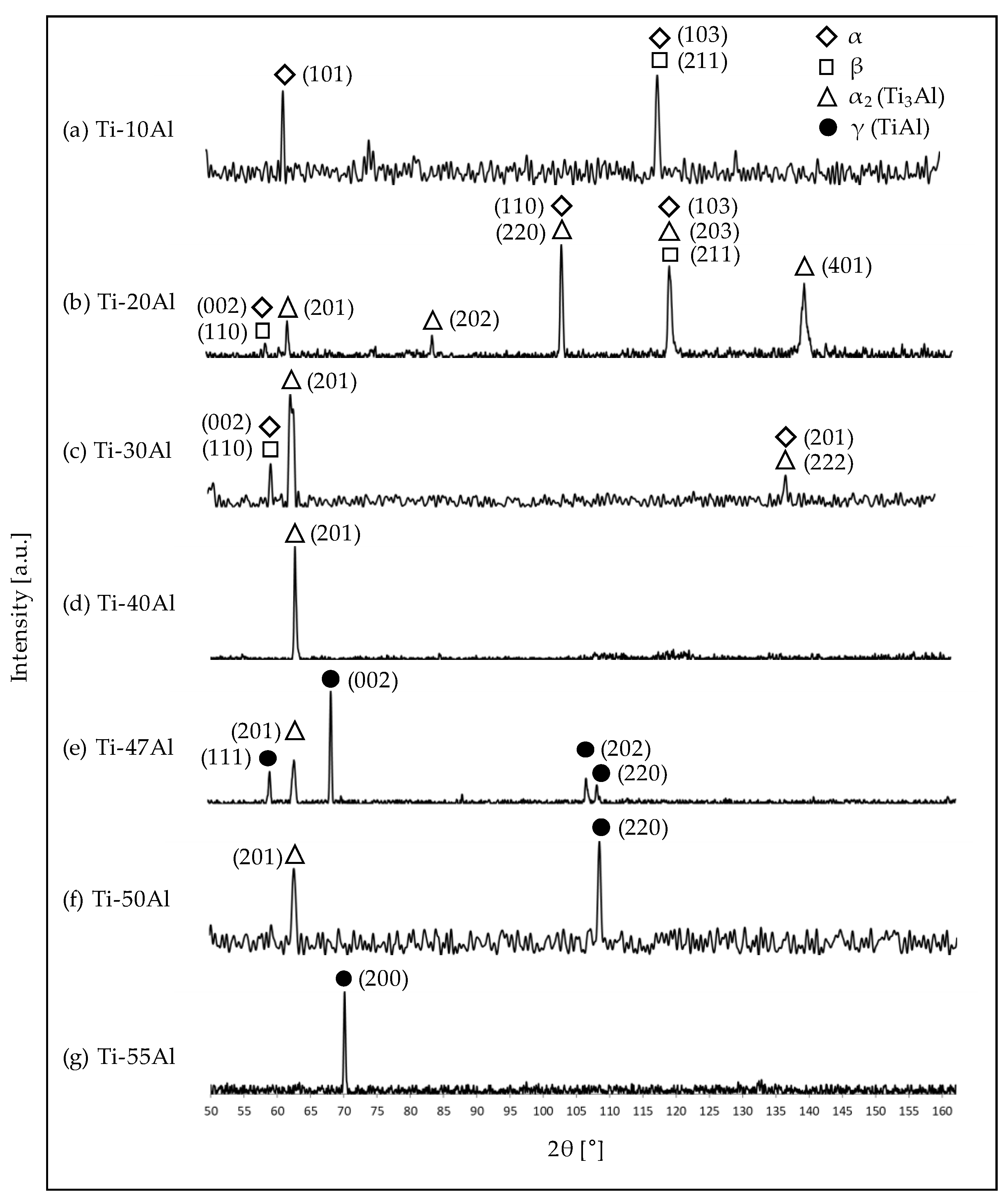
4.5. Phase Identification of Ti–Al Alloys with Differing Aluminum Content

The verification of the shown microstructures and further identification of the occurring phases was performed by XRD analysis on the cross sections shown in Figure 5. All measured intensities of the differing phases were normalized in a value range of 0–1. The diffractograms for differing alloy compositions with aluminum contents between 10 at% and 55 at% are shown in Figure 7. Reference data files for the α-phase [25], β-phase [26], α2-phase [27], and γ-phase [28] were used for phase classification. As a result of references [25,26,27,28], data acquisition was examined between 50° and 160° angles (2θ).
Titanium alloy with 10 at% aluminum content (compare Figure 7a) shows the formation of α and β-phases. With an increasing aluminum content of 20 at% and 30 at%, an additional α2-phase is formed to the existing α- and β-phases (see Figure 7b,c). Particularly, the sample with 20 at% aluminum shows significant peaks in the diffractogram correlating to these phases. In comparison, the proportion of the α2-phase increases (peak at 2θ of approximately 63°) with a rising aluminum content of 30 at%. However, the diffractogram of Ti–40Al alloy shows a single peak for the α2-phase. This correlates to the cross section in Figure 5d, where α2-phase formation was shown with γ-phase growth; whereas the concentration of α2-phase decreases significantly within the Ti–47Al (see Figure 7e). Herein, the presence of the γ-phase can be confirmed. A similar phase formation is shown for an aluminum concentration of 50 at%. A further increase in the Al content to 55 at% shows a single peak for the γ-phase at approximately 70° (2θ). These investigations verify the microstructures shown in Figure 5. The different positions of the peak values are due to the respective grain orientation, resulting from a reflected X-ray radiation by another diffracting plane.

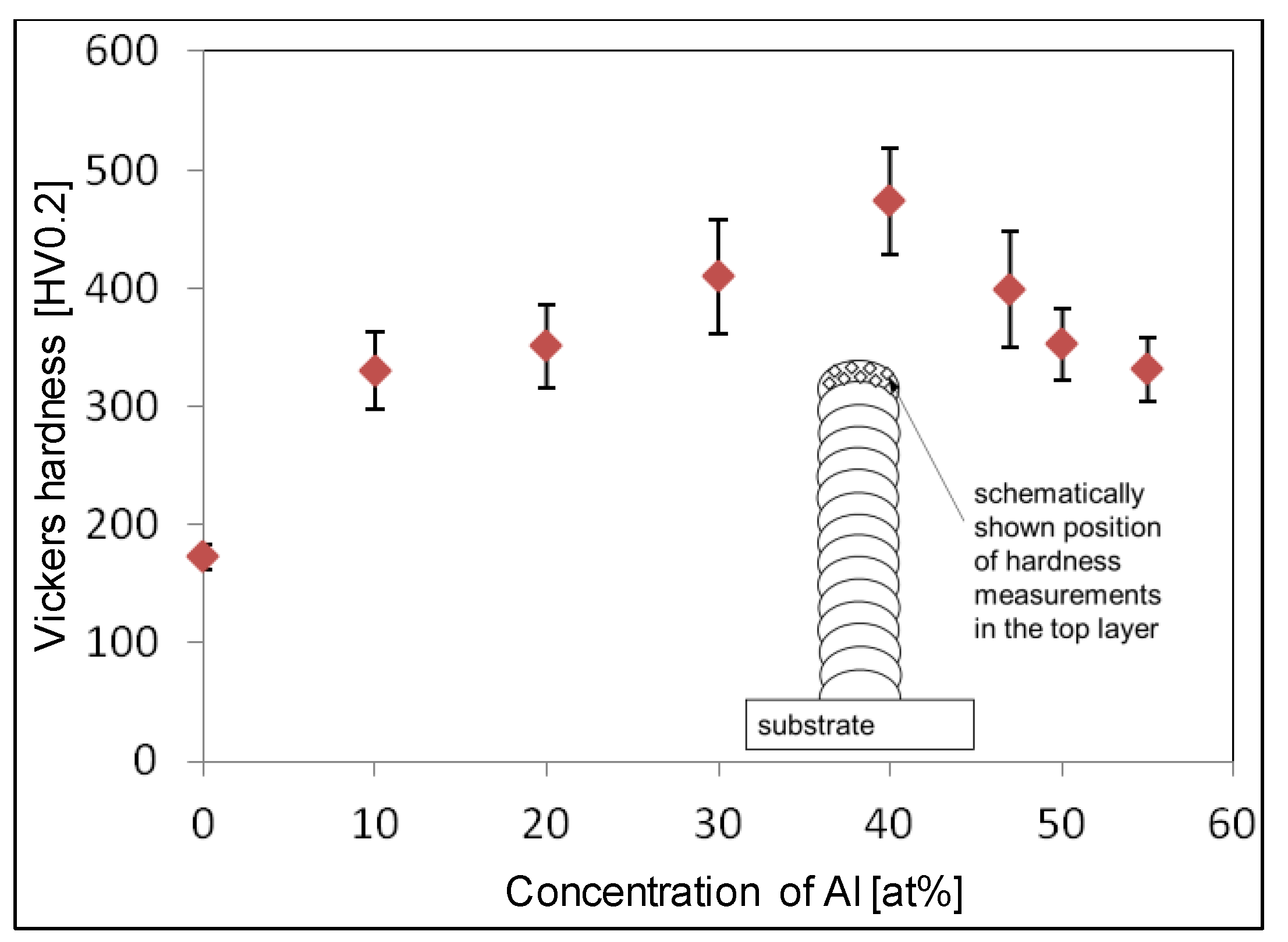
4.6. Influence of Alloy Composition on Microhardness

Hardness measurements were examined in the top layer of the additively built wall structures as a result of insufficient dilution of titanium and aluminum with Al contents of ≥40 at%. Therefore, 32 measurements were executed for every alloy with a distance between the indentations of 0.5 mm. The Vickers testing method was applied. Figure 8 shows the mean values of hardness measurements depending on the aluminum concentration in the Ti–Al alloy. Furthermore, the positions of hardness measurements in the top layer of each structure are schematically shown.
As a reference, an additively generated wall structure without additional aluminum was measured. The mean hardness of this structure was 172 ± 11 HV0.2. With increasing aluminum concentration, the hardness values of the generated structures increased to a maximum of 473 ± 44 HV0.2 at 40 at% aluminum. A further increase in the aluminum concentration to 55 at% led to a decrease of the microhardness in the manufactured 2D structures. Thus, an alloy composition of 55 at% aluminum resulted in a material hardness of 331 ± 27 HV0.2. The hardness profile is based on the formation of the microstructure and the respective phase concentration. Thus, an increase in the aluminum content from initially 0 at% to 40 at% aluminum leads to an increased proportion of α2-phase and decreased content of the α-phase. Therefore, the microhardness reached its peak value due to the high concentration of the brittle α2-phase. A further increase in the aluminum concentration shows a lower α2-phase proportion, leading to a simultaneous increase of the γ-phase concentration, which is characterized by a lower microhardness. The results correlate to the shown phases in cross sections (a–f) in Figure 5. Moreover, XRD analysis confirmed the formation of the phases shown in Figure 7.

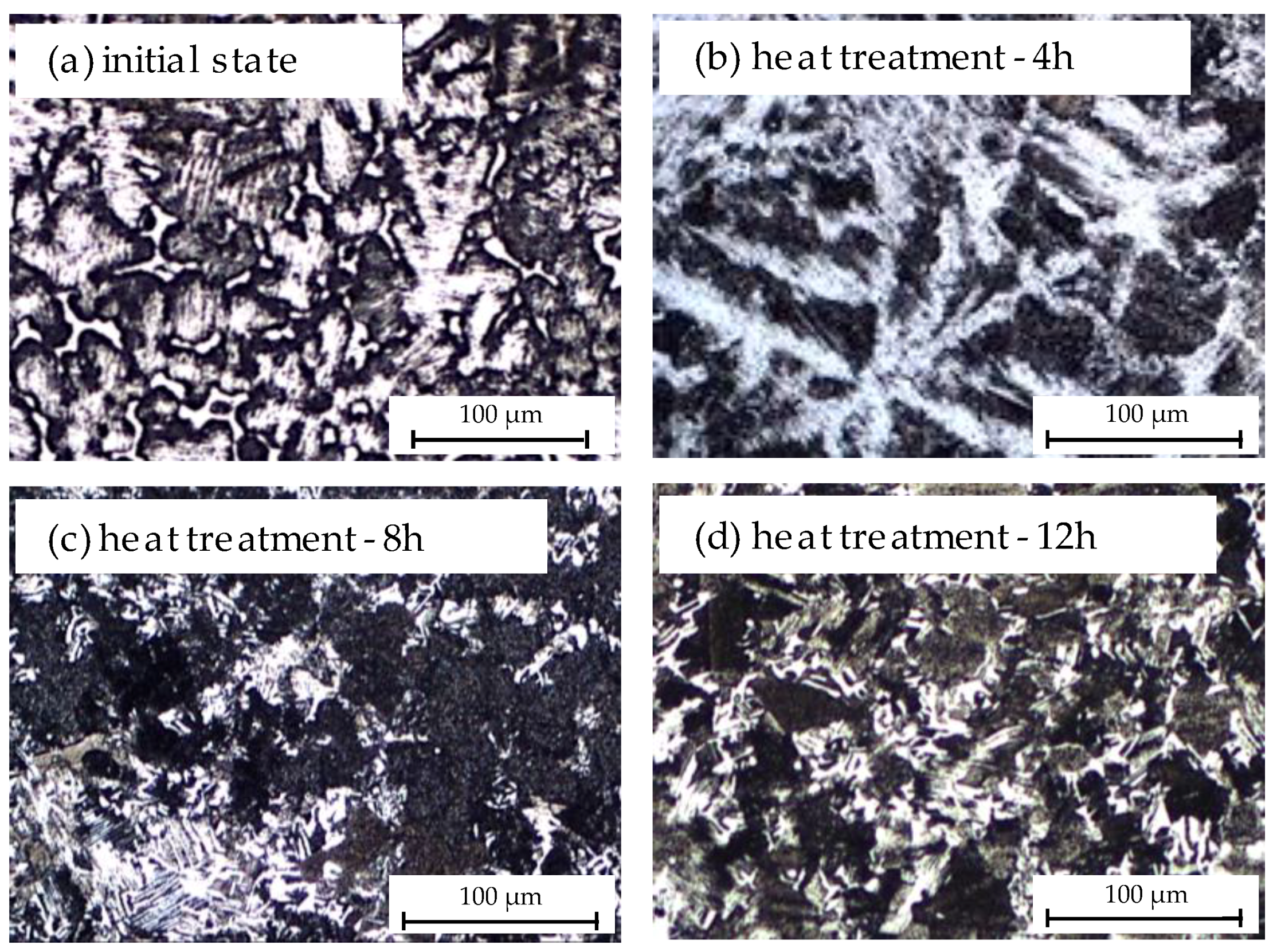
4.7. Influence of Post-Heat Treatment on the Microstructure of Ti–47Al Alloy

Further investigations on microstructure were conducted by means of post-heat treatment on additively manufactured 2D structures. Figure 9 shows cross sections of Ti–47Al alloy in its initial state (as fabricated) as well as post-heat treated. The cross sections were taken from the top layer of the manufactured wall structures (see Figure 5). The post-heat treatment was examined with a temperature of 1180 °C under atmospheric conditions for a period of 4 h, 8 h, and 12 h. The temperature was set above the eutectoid temperature (Te) of 1120 °C, whereas a reduction of dendritic and interdendritic areas with progressing time could be implemented. The oven was preheated and the samples were cooled to room temperature by air cooling afterwards. According to Peters et al. [29], an α/γ-ratio of 1 results in the formation of a duplex microstructure with uniaxial γ-grains with lamellar α2/γ-colonies. In differing cooling gradients, the adaption of grain size and resulting mechanical properties can be influenced. Therefore, increased cooling rates lead to sufficient ductility and tensile strength at room temperature.
The cross sections in Figure 9 show that an improvement in the microstructural composition was achieved. It can be seen that the areas with dendritic microstructure with an interdendritic γ-phase (Figure 9a, white area) can be decreased by a heat treatment period of 4 h (see Figure 9b). After 8 h and 12 h of post-heat treatment, the microstructure was converted into α2-grains and fine lamellar α2 + γ regions (compare Figure 9d). This correlates with the described phase formation in [29].

5. Conclusions

This study presents the findings from investigations into in situ alloying of titanium aluminides by applying a hot-wire assisted GMAW process. The purpose was the production of titanium aluminide alloys with adapted alloy composition throughout the systematic feeding of titanium and aluminum wire into a common melt pool. The feasibility study was applied on 2D-wall structures in layer-wise additive manufacturing with deposition rates of >1 kg/h.
Metallographic cross sections were conducted on differing alloy compositions with aluminum concentrations of 10 at% to 55 at%. It was shown that an increasing aluminum content leads to differing microstructural compositions, where the concentration of the α2-phase significantly influences the microhardness. However, it could also be shown that the microstructural composition in the built structures is not homogeneous. Areas with higher titanium concentrations occur as a result of differing densities of both filler materials. The adjustment of the welding speed showed the potential of reduced microstructural inhomogeneity and enhanced dilution of titanium and aluminum. Subsequent heat treatment resulted in a microstructural transformation from a dendritic γ-phase to a fine lamellar α2 + γ duplex microstructure. Further investigations should focus on the reduction of cold cracks in the additively built structures. Therefore, experimental trials with increased inter-pass temperature are planned.

Author Contributions

Conceptualization, P.H.; Investigation, P.H., Y.A. and A.M.; Methodology, P.H. and Y.A.; Project administration, J.P.B.; Supervision, J.P.B.; Writing—original draft, P.H. and J.R.

Funding

We acknowledge support for the article processing charge by the German Research Foundation (DFG) and the Open Access Publication Fund of the Technische Universität Ilmenau.

Conflicts of Interest

The authors declare no conflict of interest.

References

  1. Kim, Y. Ordered intermetallic alloys, part III: Gamma titanium aluminides. JOM 1994, 46, 30–39. [Google Scholar] [CrossRef]
  2. Kim, Y. Gamma Titanium Aluminide Alloy Technology: Status and Future. Acta Metall. Sin. 1999, 12, 334–339. [Google Scholar]
  3. Wu, X. Review of alloy and process development of TiAl alloys. Intermetallics 2006, 14, 1114–1122. [Google Scholar] [CrossRef]
  4. MTU Aero Engines: Backgrounder—Titanaluminid; MTU Aero Engines: Munich, Germany, 2016.
  5. Noda, T. Application of cast gamma TiAl for automobiles. Intermetallics 1998, 6, 709–713. [Google Scholar] [CrossRef]
  6. Aguilar, J.; Schievenbusch, A.; Kättlitz, O. Investment casting technology for production of TiAl low pressure turbine blades - Process engineering and parameter analysis. Intermetallics 2011, 19, 757–761. [Google Scholar] [CrossRef]
  7. Janschek, P. Geschmiedete Turbinenschaufeln aus Titanaluminid—Ein Neuer Werkstoff Lernt Fliegen; IMFOKUS: Tumeltsham, Austria, 2016. (In German) [Google Scholar]
  8. Kothari, K.; Radhakrishnan, R.; Wereley, N.M. Advances in gamma titanium aluminides and their manufacturing techniques. Prog. Aerosp. Sci. 2012, 55, 1–16. [Google Scholar] [CrossRef]
  9. Thomas, M.; Raviart, J.L.; Popoff, F. Cast and PM processing development in gamma aluminides: 2nd IRC International TiAl Workshop. Intermetallics 2005, 13, 944–951. [Google Scholar] [CrossRef]
  10. Gerling, R.; Clemens, H.; Schimansky, F.P. Powder metallurgical processing of intermetallic gamma titanium aluminides. Adv. Eng. Mater. 2004, 6, 23–38. [Google Scholar] [CrossRef]
  11. Petrovica, V.; Gonzalez, J.V.H.; Ferrandoa, O.J.; Gordillo, J.D.; Puchades, J.R.B.; Grinan, L.P. Additive layered manufacturing sectors of industrial application shown through case studies. Int. J. Prod. Res. 2011, 49, 1061–1079. [Google Scholar] [CrossRef]
  12. Chen, J. Hybrid Design Based on Wire and Arc Additive Manufacturing in the Aircraft Industry. Master Thesis, Cranfield University, Cranfield, UK, December 2012. [Google Scholar]
  13. Ding, J. Thermo-mechanical Analysis of Wire and Arc Additive Manufacturing Process. Ph.D. Thesis, Cranfield University, Cranfield, UK, January 2012. [Google Scholar]
  14. Baufeld, B. Effect of deposition parameters on mechanical properties of shaped metal deposition parts. J. Eng. Manuf. 2012, 226, 126–136. [Google Scholar] [CrossRef]
  15. Brandl, E.; Baufeld, B.; Leyens, C. Additive manufactured Ti-6Al-4v using welding wire: Comparison of laser and arc beam deposition and evaluation with respect to aerospace material specifications. Phys. Procedia 2010, 5, 595–606. [Google Scholar] [CrossRef]
  16. Murr, L.E.; Gaytan, S.M.; Ceylan, A.; Martinez, E.; Martinez, J.L.; Hernandez, D.H.; Machado, B.I.; Ramirez, D.A.; Medina, F.; Collins, S.; et al. Characterization of titanium aluminide alloy components fabricated by additive manufacturing using electron beam melting. Acta Mater. 2010, 58, 1887–1894. [Google Scholar] [CrossRef]
  17. Biamino, S.; Penna, A.; Ackelid, U.; Sabbadini, S.; Tassa, O.; Fino, P.; Pavese, M.; Gennaro, P.; Badini, C. Electron beam melting of Ti-48Al-2Cr-2Nb alloy: Microstructure and mechanical properties investigation. Intermetallics 2011, 19, 776–781. [Google Scholar] [CrossRef]
  18. Qu, H.P.; Wang, H.M. Microstructure and mechanical properties of laser melting deposited γ-TiAl intermetallic alloys. Mater. Sci. Eng. A 2007, 466, 187–194. [Google Scholar] [CrossRef]
  19. Srivastava, D.; Chang, I.T.H.; Loretto, M.H. The optimisation of processing parameters and characterisation of microstructure of direct laser fabricated TiAl alloy components. Mater. Des. 2000, 21, 425–433. [Google Scholar] [CrossRef]
  20. Gasper, A.N.D.; Catchpole-Smith, S.; Clare, A.T. In-situ synthesis of titanium aluminides by direct metal deposition. J. Mater. Process. Technol. 2017, 239, 230–239. [Google Scholar] [CrossRef] [Green Version]
  21. Ma, Y. Fabrication of Gamma Titanium Aluminide Alloys by Gas Tungsten Arc Welding-Based Additive Layer Manufacturing. Ph.D. Thesis, University of Wollongong, Wollongong, Australia, March 2015. [Google Scholar]
  22. Ratke, L. Phasengleichgewichte in Werkstoffen; German Aerospace Center: Cologne, Germany, 2008. [Google Scholar]
  23. Zhang, Y.M.; Li, P.J. Modified Active Control of Metal Transfer and Pulsed GMAW of Titanium. Weld. J. 2001, 80, 54–61. [Google Scholar]
  24. Appel, F.; Paul, J.D.H.; Oehring, M. Gamma Titanium Aluminide Alloys: Science and Technology; Wiley: Hoboken, NJ, USA, 2011. [Google Scholar]
  25. Swanson, H.E.; Gilfrich, N.T.; Cook, M.I.; Strinchfield, R.; Parks, P.C. Circular of the Bureau of Standards No. 539 Volume 8: Standard X-ray Diffraction Powder Patterns; US Department of Commerce, National Institute of Standards and Technology: Gaithersburg, MD, USA, 1959.
  26. Levinger, B.W. Lattice parameter of beta titanium at room temperature. JOM 1953, 5, 195. [Google Scholar] [CrossRef]
  27. Braun, J.; Ellner, M. On the partial atomic volume of aluminium in the titanium-rich phases of the binary system Ti-Al. Zeitschrift für Metallkunde 2000, 91, 389–392. [Google Scholar]
  28. Sridharan, S.; Nowotny, H. Studies in the ternary system Ti-Ta-Al and in the quaternary system Ti-Ta-Al-C. Zeitschrift für Metallkunde 1983, 74, 468–472. [Google Scholar]
  29. Peters, M.; Leyens, C. Titan und Titanlegierungen; Wiley: Hoboken, NJ, USA, 2002. [Google Scholar]
Figure 1. (a) Experimental setup of the gas metal arc welding process (GMAW) with additional hot-wire process and (b) schematic depiction of the GMAW process with additional hot wire process with geometric parameters.
Metals 09 00578 g001
Figure 2. Investigations into the process behavior with (a) spray arc (b) and pulse arc welding regimes with GMAW process and in situ processing of Ti–Al alloys with (c) 10% Al and (d) 20% Al with pulsed GMAW and hot wire with resulting cold cracks (red arrows).
Metals 09 00578 g002
Figure 3. Wire arc additive manufacturing of wall structures of Ti–Al with differing content of Al (a) 10 at%, (b) 20 at%, (c) 47 at% and resulting cold cracks (b), (c). RT = room temperature.
Metals 09 00578 g003
Figure 4. Cross sections of Ti–Al samples with aluminum concentrations of (a) 10 at%, (b) 40 at%, (c) 47 at%.
Metals 09 00578 g004
Figure 5. Analysis of the microstructure for Ti–Al alloys with differing aluminum content of (a) 10 at%, (b) 20 at%, (c) 30 at%, (d) 40 at%, (e) 47 at%, (f) 55 at%.
Metals 09 00578 g005
Figure 6. Influence of welding speed on microstructural composition of Ti–47Al alloy; (a) 0.15 m/min, (b) 0. 2 m/min, (c) 0.25 m/min, (d) 0.3 m/min, (e) 0.35 m/min, (f) 0.4 m/min
Metals 09 00578 g006
Figure 7. Diffractogram for Ti–Al alloys with differing aluminum content; (a) 10 at%, (b) 20 at%, (c) 30 at%, (d) 40 at%, (e) 47 at%, (f) 55 at%.
Metals 09 00578 g007
Figure 8. Hardness values of Ti–Al alloys dependent on aluminum concentration.
Metals 09 00578 g008
Figure 9. Cross sections of a Ti–47Al alloy in initial state (a) and after heat treatment of 4 h (b), 8 h (c), and 12 h (d).
Metals 09 00578 g009
Table 1. Chemical composition of substrate, welding wire, and hot wire (%).
FunctionMaterialNmaxCmaxOmaxSimaxFemaxTimaxAlmax
substrateTi Grade 2 (3.7035)0.030.080.25-0.30balance-
welding wireTi99.6 (3.7036)0.0150.080.16-0.12balance-
hot wireAl99.5Ti (3.0805)---0.050.210.15balance
Table 2. Hot-wire feeding rates for varying Al concentrations between 10 at% and 55 at% in Ti–Al.
Aluminum Concentration (at%)10203040475055
Hot-wire Feeding Rate (m/min)0.4180.9421.6142.5113.343.7674.603
Table 3. Relevant intermetallic phases in binary Ti–Al phase diagram [24].
PhaseSymbolAluminum Content in (at%)
Ti3Alα218–39
TiAlγ48–62
TiAl2ƞ66–67
TiAl3ε74–75
Ti2Al5ζ64–73

