Article

Influence of Austenite Grain Size on Mechanical Properties after Quench and Partitioning Treatment of a 42SiCr Steel

1
Virtual Production Engineering, Technische Universität Chemnitz, 09107 Chemnitz, Germany
2
Welding Engineering, Technische Universität Chemnitz, 09107 Chemnitz, Germany
3
Materials Science, Technische Universität Chemnitz, 09125 Chemnitz, Germany
4
Regional Technological Institut, University of West Bohemia, 301 00 Pilsen, Czech Republic
5
COMTES FHT, Průmyslová 995, 33441 Dobřany, Czech Republic
*
Author to whom correspondence should be addressed.
Metals 2019, 9(5), 577; https://doi.org/10.3390/met9050577
Submission received: 22 March 2019 / Revised: 13 May 2019 / Accepted: 16 May 2019 / Published: 18 May 2019

Abstract

:
This paper examines how the initial austenite grain size in quench and partitioning (Q-P) processes influences the final mechanical properties of Q-P steels. Differences in austenite grain size distribution may result, for example, from uneven heating rates of semi-finished products prior to a forging process. In order to quantify this influence, a carefully defined heat treatment of a cylindrical specimen made of the Q-P-capable 42SiCr steel was performed in a dilatometer. Different austenite grain sizes were adjusted by a pre-treatment before the actual Q-P process. The resulting mechanical properties were determined using the upsetting test and the corresponding microstructures were analyzed by scanning electron microscopy (SEM). These investigations show that a larger austenite grain size prior to Q-P processing leads to a slightly lower strength as well as to a coarser martensitic microstructure in the Q-P-treated material.

Graphical Abstract

1. Introduction

The development of new steel grades, characterized by very high strengths and reasonably good ductility (i.e., advanced high strength steels; AHSS), is a key requirement to realize innovative light-weight concepts. For instance, in recent years, the press hardening process for the production of sheet metal components from manganese–boron steels has been researched in depth [1].
In this paper, a 42SiCr steel is studied. This steel grade provides a good opportunity to produce advanced high strength products using bulk forming processes and a subsequent Q-P process. In this Q-P process (shown schematically in Figure 1), the austenitic material is quenched rapidly to promote the martensitic transformation, but the cooling is stopped at a quench-temperature QT prior to reaching the martensite finish temperature. This results in a microstructure composed of martensite and some retained austenite. Then, the material is briefly held at constant temperature (the partitioning temperature; this temperature is typically somewhat higher than the quench-temperature to increase diffusion rates). Diffusion of carbon from the supersaturated martensite into the adjacent austenite occurs during this short, low-temperature heat treatment and results in stabilization of the retained austenite [2]. This is allows to maintain volume fractions of, for example, about 10% of retained austenite even after subsequent cooling to room temperature (see [3]). The resulting Q-P steels typically exhibit good ductility in addition to high strength: carbon diffusion contributes to a partial reduction of the internal stresses in the martensite phase and this, combined with the more ductile retained austenite makes the material no longer as brittle as conventional fully martensitic steels.
In various investigations, alloy concepts for the Q-P process have been developed, starting from low-alloyed steel grades [4,5,6,7] up to stainless steels [8]. The main alloying elements are Mn, Si, and sometimes Cr and Ni. It has been shown that optimum QT temperatures depend on the alloy composition, and that the PT temperature should be between 180 °C and 400 °C [8]. Furthermore, it was demonstrated that the mechanical properties can be influenced by partitioning time because the microstructural evolution is based on diffusion-controlled processes [4,5]. In [9], Q-P processes with different time-temperature regimes were investigated on the steel 42SiCr. Q-P processes, which are comparable to heat treatment route 1 (used in this paper), were also investigated. After this thermal treatment, a retained austenite content of ~8% could be detected. The resulting mechanical properties, measured by tensile testing, were characterized by a maximum strength of 2,000 MPa and an elongation at fracture of ~15%.
Other possible influencing factors, such as the initial microstructural state in austenite prior to quenching, have not yet been investigated in detail. In this work, the influence of austenite grain size at the beginning of the Q-P process on the resulting microstructures and mechanical properties is investigated in a 42SiCr steel using a carefully controlled laboratory Q-P process performed in a dilatometer. This investigation is motivated by the observation that heating of forged components takes place from the outside to inside (e.g., in the radiant oven). The outer regions reach the austenitizing temperature sooner than the inner regions, and therefore more pronounced grain growth can take place in the outer regions before the actual Q-P treatment is applied.

2. Materials and Methods
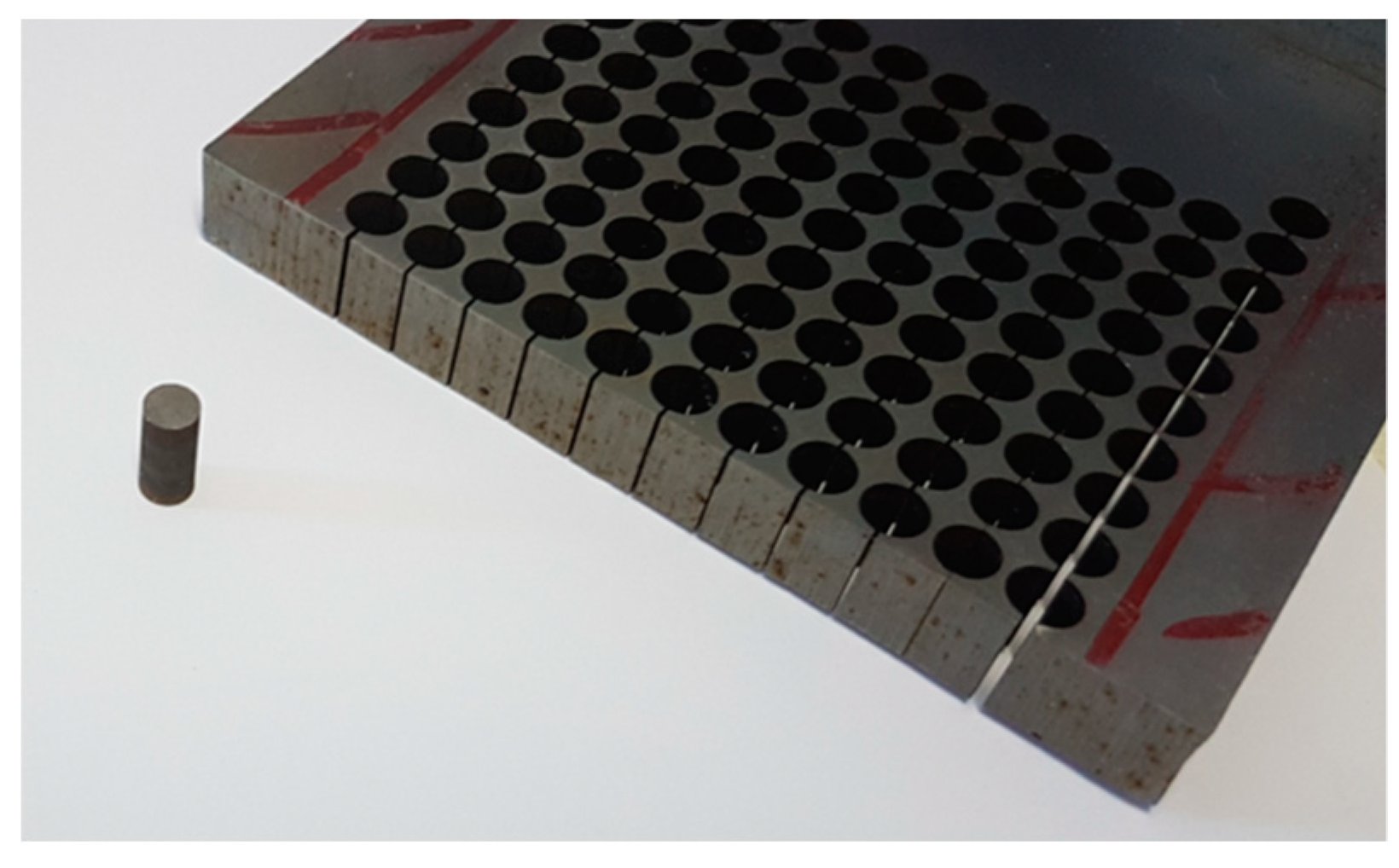
2.1. Materials

The material used for the experimental investigations was an AHS steel 42SiCr with the chemical composition summarized in Table 1. The chemical composition was determined using a SPECTROMAXx metal analyzer (SPECTRO Analytical Instruments GmbH, Kleve, Germany) in combination with optical emission spectrometry (OES).
The semi-finished product was a 10 mm thick plate made by hot rolling and final annealing. The steel for the semi-product was prepared by a standard metallurgical vacuum process and cast into molds. The 2000 kg block was gradually hot rolled to a diameter of 150 mm and then to a 10 mm plate. The plate was slowly cooled from the end-rolling temperature of 900 °C to RT. Finally, the plate was normalized at 860 °C for 4 h and then slowly cooled down to RT. From this plate, cylinder specimens with a height H = 8 mm and a diameter D = 4 mm were cut (cylindrical axis in thickness direction) by means of wire EDM (electrical discharge machining). The front faces of the specimens were ground plane. The semi-finished product and a specimen are shown in Figure 2.
The hardening behavior of the normalized steel 42SiCr was determined by upsetting tests. The corresponding flow curve is shown in Figure 3. The flow curve shows that in the normalized state the material had an initial flow stress of ~500 MPa and hardened to ~1,150 MPa at a plastic strain of 0.3.
To document the microstructure of the AHS steel 42SiCr, optical microscopy (Zeiss, Oberkochen, Germany), after etching with alcoholic nitric acid (2%) etchant, was performed. Figure 4 shows an optical micrograph of the normalized steel. In this material state, there is a perlitic-ferritic microstructure.

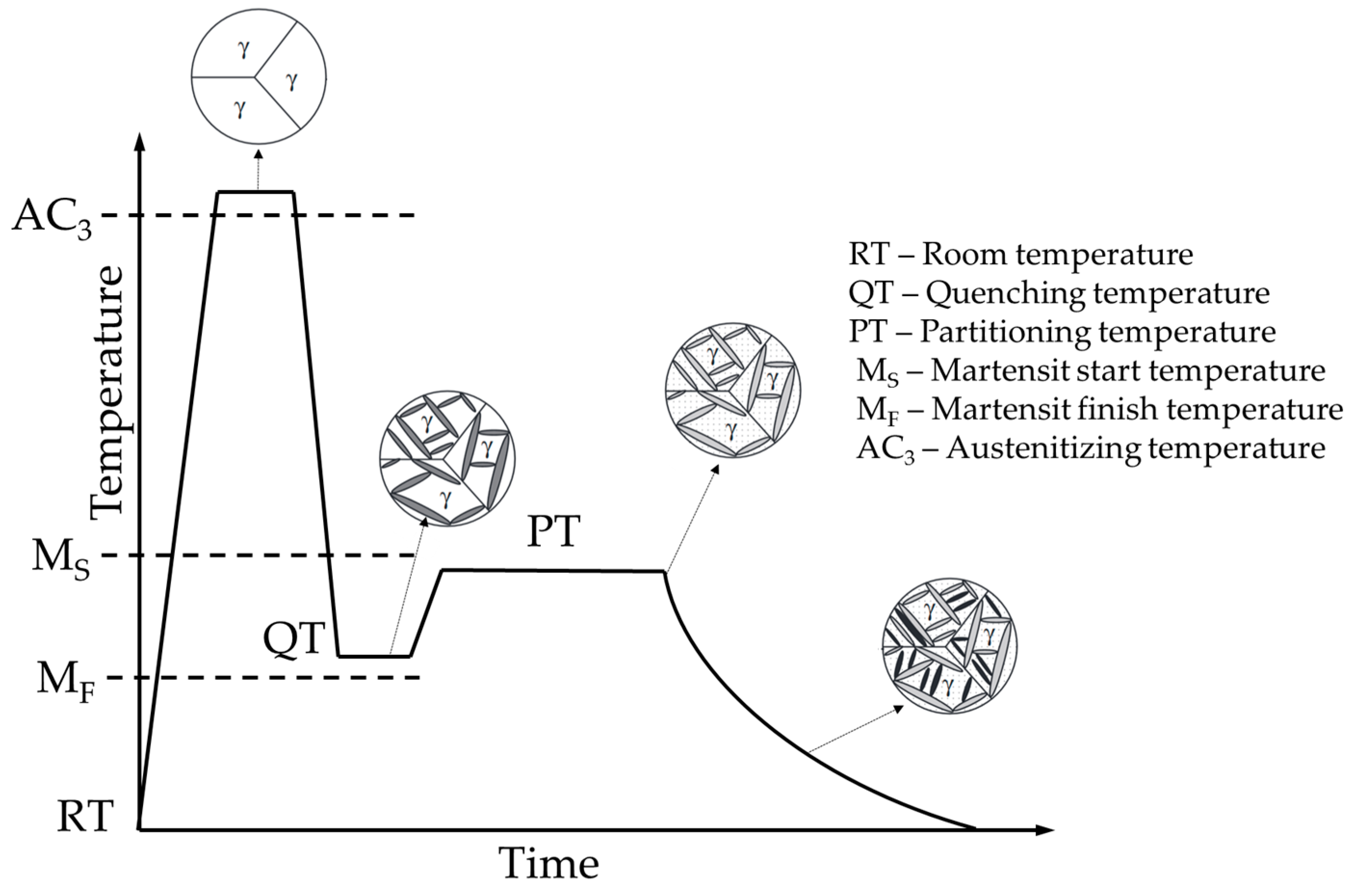
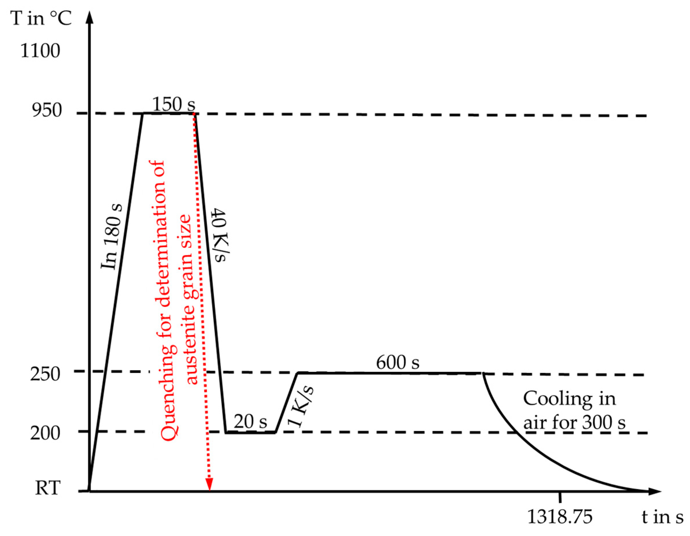
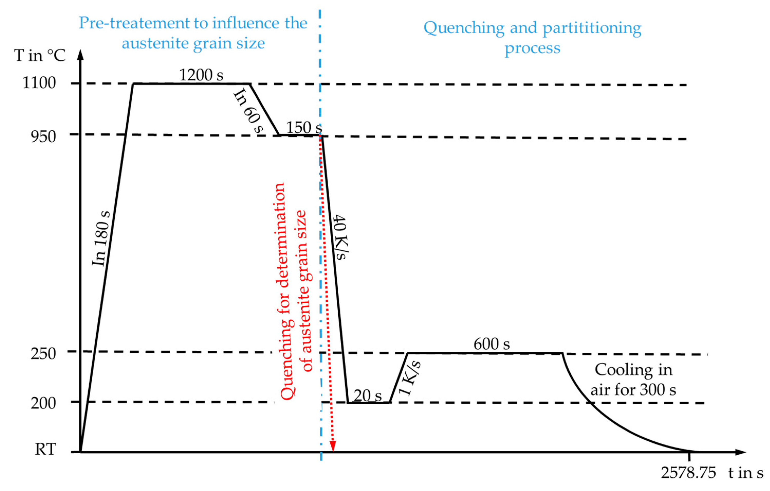
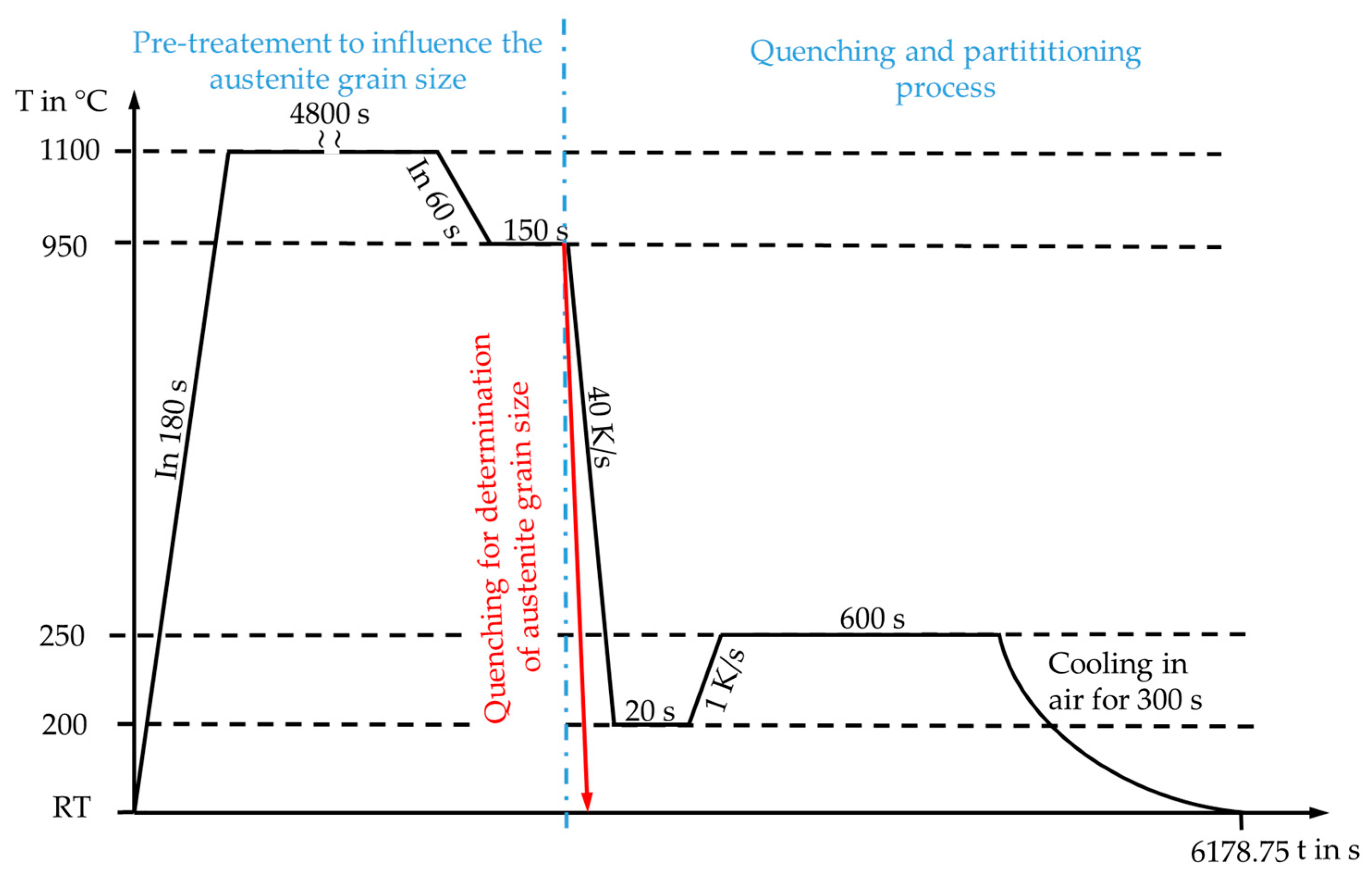
2.2. Method of Heat Treatment

The subsequent heat treatments of the cylindrical specimens were carried out on a forming and quenching dilatometer “DIL 805 A/D” (Bähr Thermoanalyse GmbH now TA Instruments, Hüllhorst, Germany). On the one hand, specimens were produced for subsequent mechanical testing in the upsetting test and for SEM analysis of the resulting microstructures. On the other hand, additional specimens were quenched after austenitizing or different pre-treatments in order to preserve the current microstructure and thus to be able to determine austenite grain size prior to the Q-P process. This was done by optical microscopy, after etching with Vilella etchant (100 mL of ethanol, 5 mL of HCl and 1 g of picric acid).
In a first step, the Q-P treatment of the as-delivered material was carried out as shown schematically in the temperature-time profile in Figure 5. The figure also shows the quenching process for determining austenite grain size.
In order to analyze the influence of austenite grain size on mechanical properties and microstructural features, different heat treatment routes were studied, leading to an increase in austenite grain size before the beginning of the Q-P process (heat treatment routes 2 and 3, Figure 6 and Figure 7). These heat treatments were subdivided into the sections “pre-treatment to influence the austenite grain size” and the actual “quenching and partitioning process” performed afterwards. To produce a coarse-grained microstructure prior to the Q-P process, the specimens were heated within 180 s to 1,100 °C and held at this temperature for 1,200 s (see Figure 6) and 4,800 s (see Figure 7), respectively, then cooled to 950 °C in 60 s. After a holding time of 150 s, the final Q-P treatment took place.

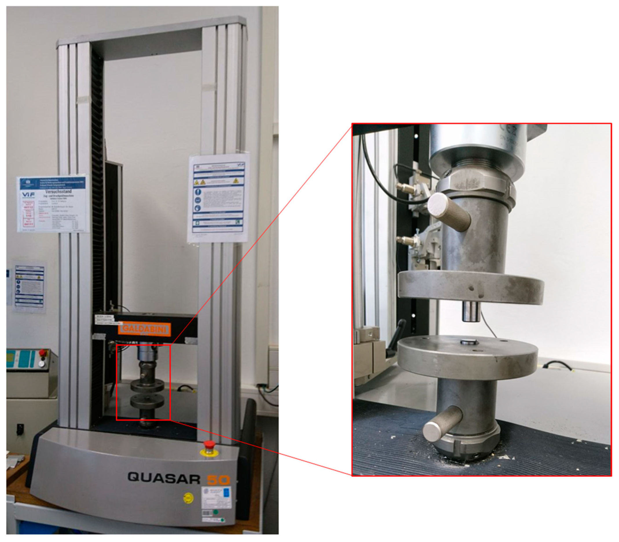
2.3. Determination of Mechanical Properties

The mechanical properties of the differently thermally treated specimens were determined by upsetting tests on a Quasar 50 kN universal testing machine (Galdabini S.p.A, Cardano Al Campo, Italy). Carbide punches made from K-40UF (hardness: 1610 HV 30, flexural strength: >4,200 MPa) were used as upsetting tools. These tool strengths were required to determine the expected high strengths of the material without tool damage. The experimental setup is shown in Figure 8.
The upsetting tests were carried out with a constant punch speed of 0.07 mm/s and a punch stroke of 4 mm. Both the punch force and the stroke were measured in order to calculate the corresponding flow curves at room temperature. Graphite spray was used to reduce friction. The flow curves were also determined taking into account the necessary correction of friction as described for instance in [10].

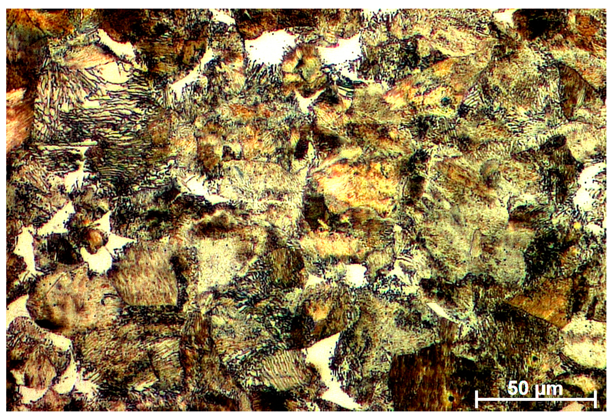
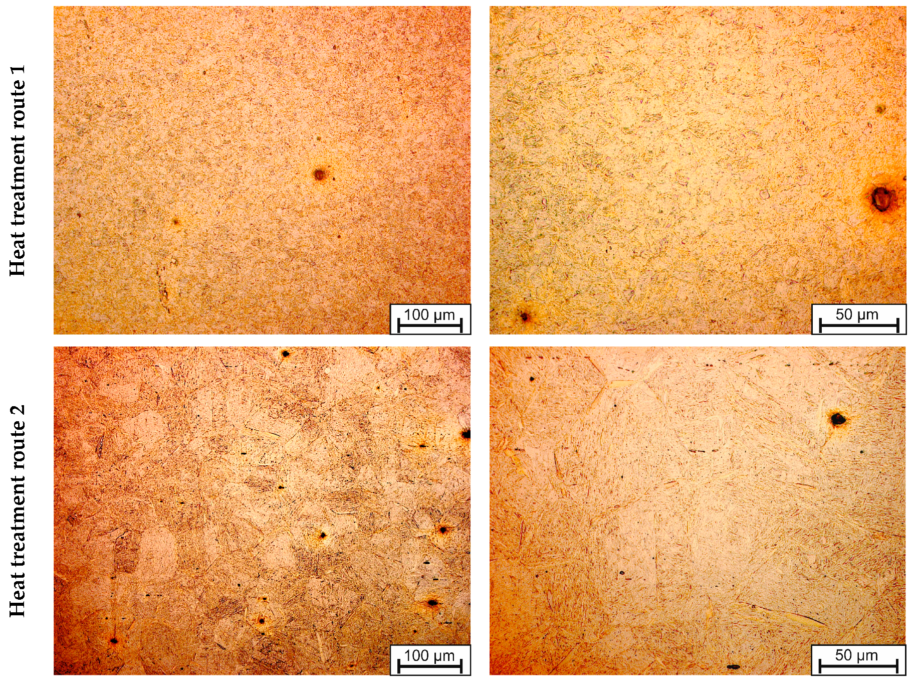
2.4. Microstructure Analysis after Q-P Treatment

For microstructure analysis after Q-P treatment, samples were cut from the center of the cylinders and embedded in epoxy resin. Grinding and polishing was carried out on a TegraPol-35 system equipped with a Tegra-Force-5 (STRUERS GmbH, Willich, Germany) for defined polishing pressures. After final polishing with colloidal silica suspension (OP-U, STRUERS GmbH, Willich, Germany) the samples were immersion-etched for 4 s in ethanol containing 2% nitric acid. The samples were partially masked with aluminum foil and coated with a thin carbon layer to reduce surface charging in the SEM. Scanning electron micrographs of the etched and demasked sample surfaces were obtained in a NEON 40 EsB field-emission SEM (Carl Zeiss AG, Oberkochern, Germany) operated at an acceleration voltage of 5 kV.

2.5. Determination of Fraction of Retained Austenite

For determining the fraction of retained austenite, X-ray diffraction (XRD) measurements were performed utilising a D8 Discover diffractometer (Bruker AXS GmbH, Karlsruhe, Germany) with Co-Kα radiation (40 kV, 40 mA, point focus), a collimator with 1 mm diameter and an energy-filtered 1D Lynxeye XE detector. The evaluation of the phases’ mass fractions (austenite and martensite) was performed using the Rietveld method as implemented in the TOPAS code (Bruker AXS GmbH, Karlsruhe, Germany).

3. Results and Discussion

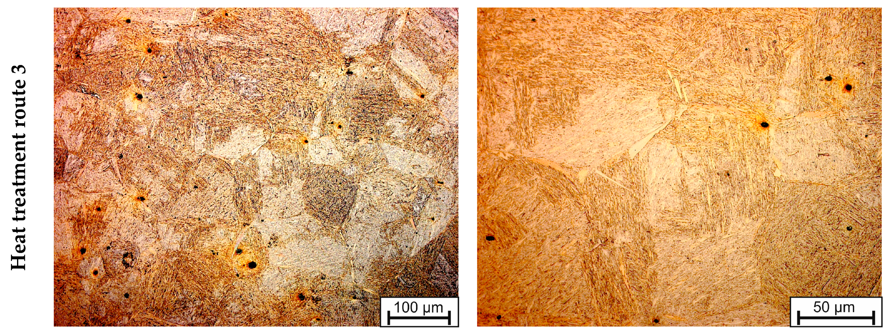
3.1. Analysis of Austenite Grain Size

In order to document the austenite grain size at the beginning of the Q-P process, specimens were quenched after the pre-treatment to preserve the microstructure. Figure 9 shows the micrographs after quenching. Due to the quenching, a fully martensitic microstructure is observed. The former austenite grain boundaries are clearly visible. Austenitizing by heating to 950 °C and holding the temperature for 150 s results in an average austenite grain size (determined by line intersection method) of 11 μm. The pre-treatments of routes 2 and 3 lead to a significant growth of the austenite grains. After annealing for 1,200 s at 1,100 °C, an austenite grain size of 60 μm is achieved (route 2). Increasing the annealing time to 4,800 s leads to an austenite grain growth to ~80 μm (route 3).

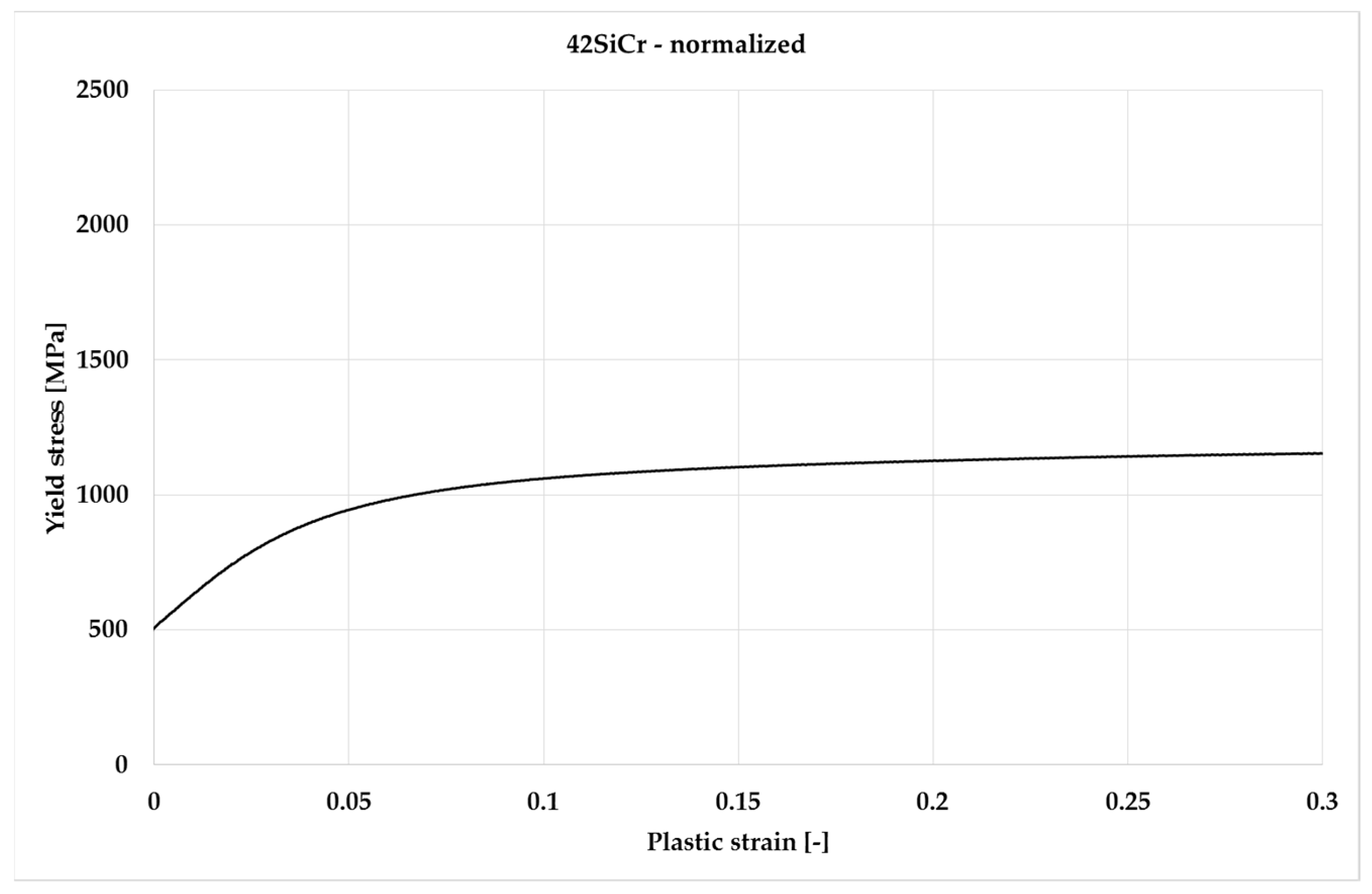
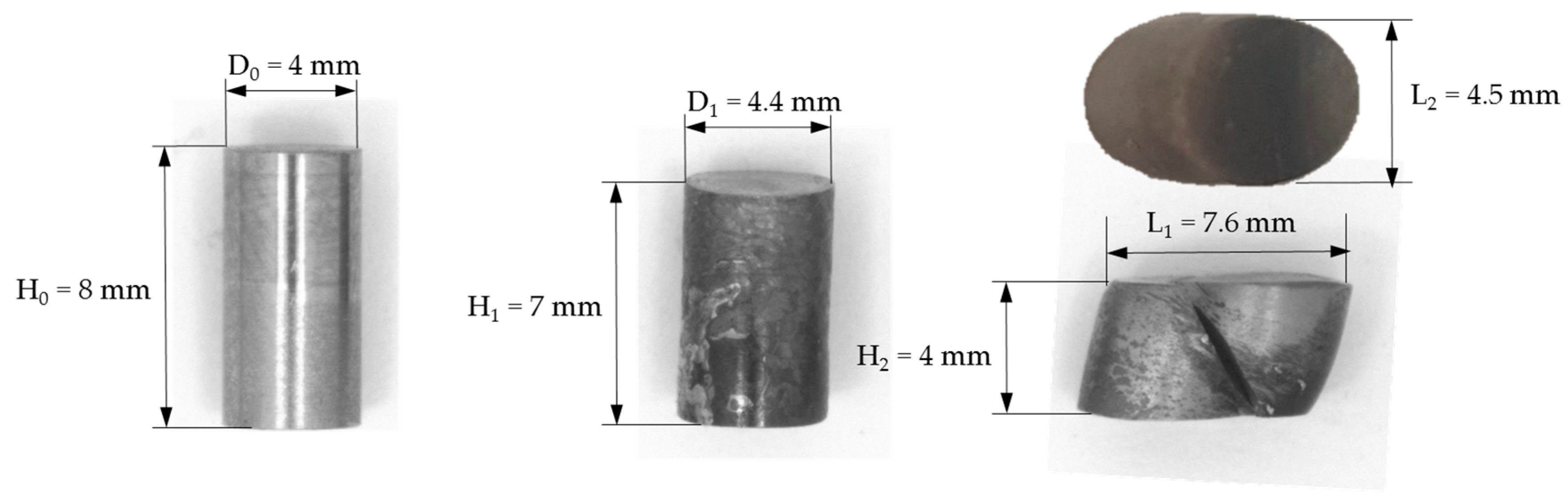
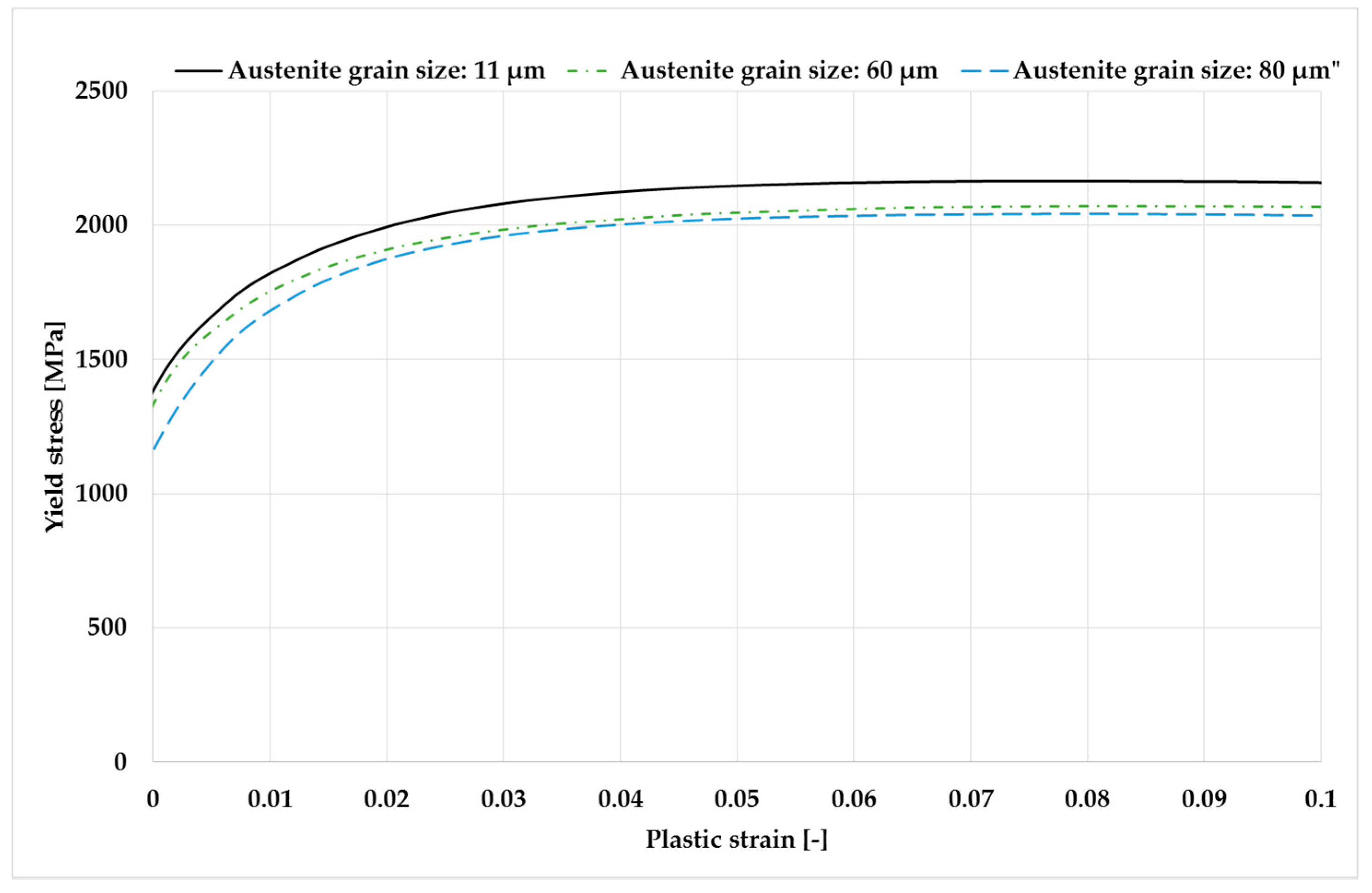
3.2. Upsetting Tests
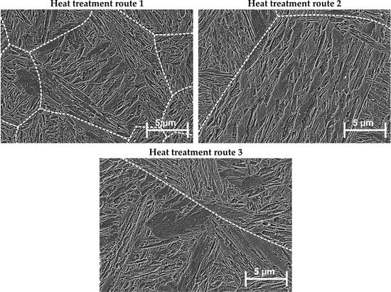
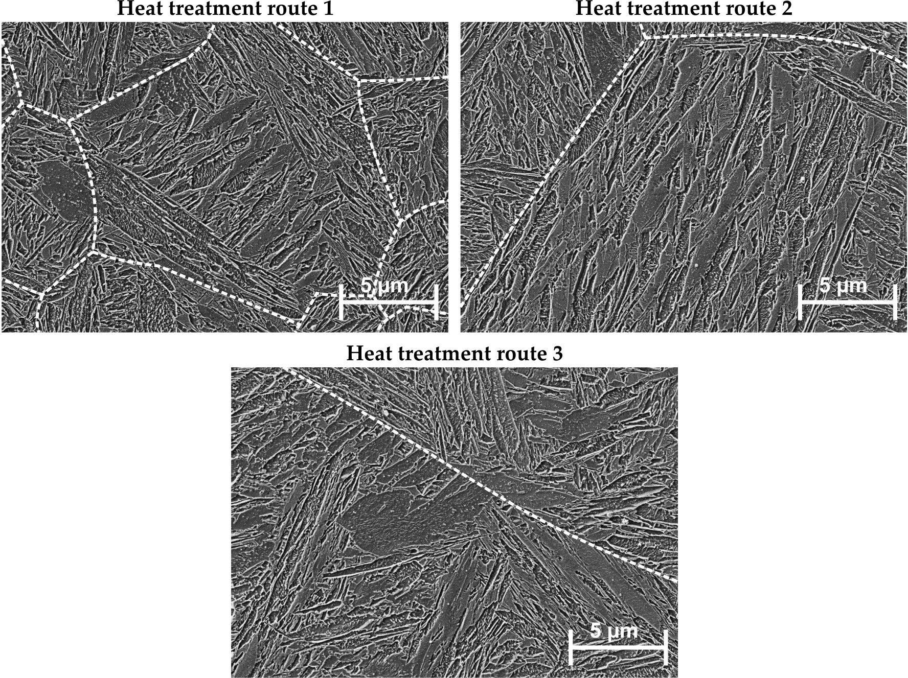
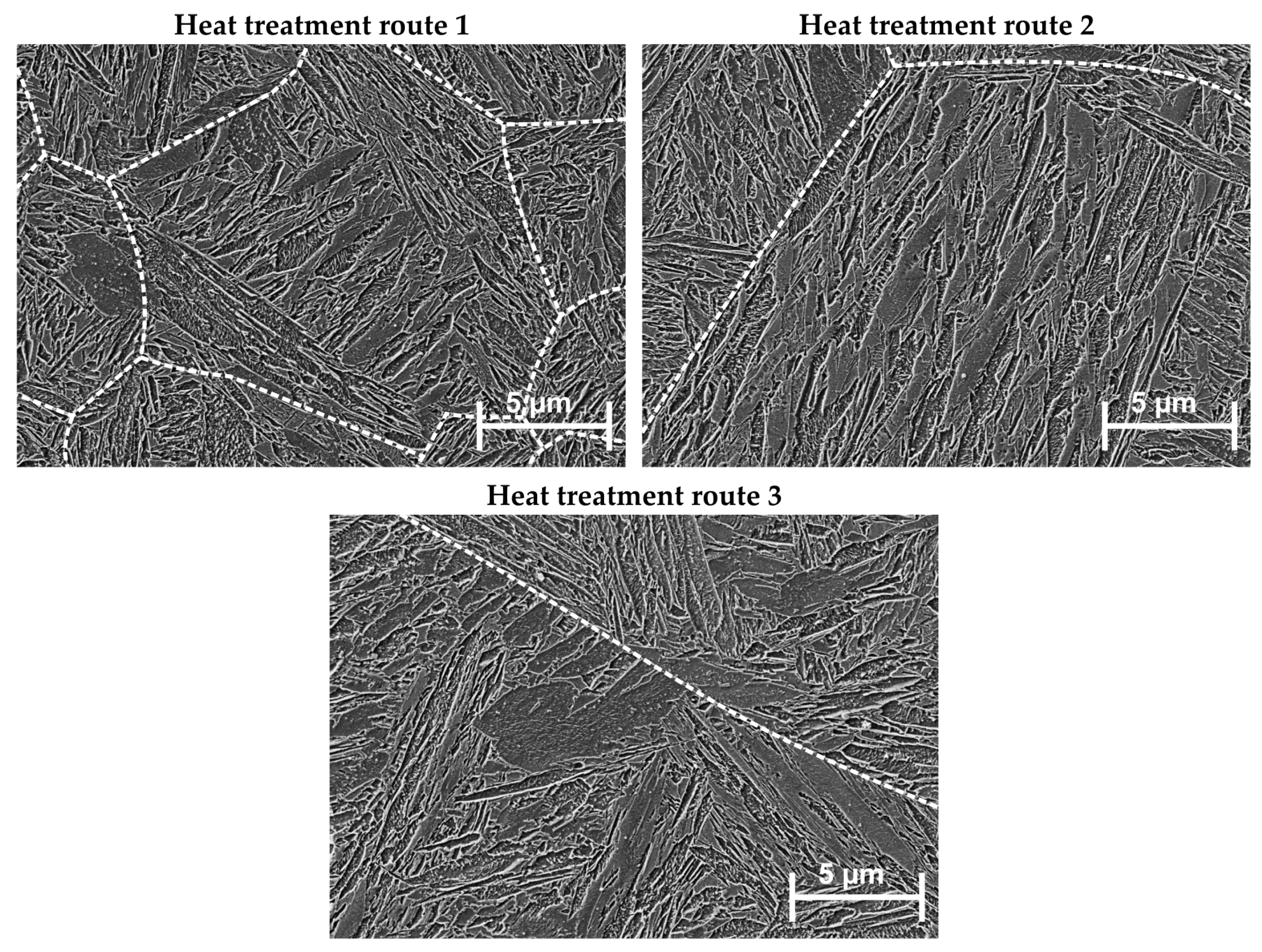
In order to analyze the influence of the austenite grain size on the mechanical properties after the Q-P process, upsetting tests were carried out on samples prepared by the heat treatment routes 1–3. The cylindrical specimens were compressed at room temperature from an initial height of 8 mm to a final height of 4 mm. Regardless of the heat treatment, it was observed that the forming limit of the specimen was already exceeded at a punch stroke of 1 mm and that brittle fractures occur. Figure 10 shows the undeformed specimen (left) and the compressed specimen at a punch stroke of 4 mm (right). The compressed specimen shows a shear deformation instead of the typical bulging of ductile materials in the upsetting test.
Consequently, in order to compare the mechanical properties of the different samples, the evaluation of the force-displacement curves was carried out only up to a punch stroke of 1 mm, because until then no material damage occurs. The flow curves were calculated from the force–displacement curves and are shown in Figure 11. The qualitative course of the flow curves (i.e., hardening behavior) is independent of the austenite grain size at the beginning of the Q-P process. However, some differences occur in terms of the maximum flow stresses achieved by work hardening. The maximum flow stress that can be achieved by work hardening is slightly depending on the austenite grain size at the beginning of the Q-P process. It can be seen that larger austenite grains prior to the Q-P process lead to a reduced maximum flow stress. Thus, the maximum flow stress of 2,165 MPa with a grain size of 11 μm was reduced to 2,040 MPa with a grain size of 80 μm.

3.3. SEM Analysis

The SEM micrographs document the influence of different prior austenite grain size on the number and size of lath packages within individual grains, Figure 12. The heat treatment route 1 (Q-P treatment of the initial material) results in finely divided martensitic plates and only few different plate packages within each grain. Coarse grain annealing in heat treatments 2 and 3 prior to the Q-P process, led to somewhat longer martensitic plates. In addition, the number of plate packages per grain also increased, while the average width of individual plates remained nearly unaffected. These slight differences in the final microstructure of the martensitic morphology after the heat treatments were carried out agree with the results on the corresponding mechanical properties. The tendency is for finer, dispersed martensitic plates, resulting from small austenite grains, to provide higher strength.

3.4. Fraction of Retained Austenite

The fraction of retained austenite was determined using X-ray diffraction (XRD) measurements, as described briefly in Section 2.5. The resulting fractions of retained austenite after heat treatment routes 1–3 and the austenite grain sizes are summarized in Table 2. The highest fraction of retained austenite of 9.9% was reached if no pre-treatment to influence the austenite grain size took place. Annealing at 1,100 °C for 1,200 s led to a slight reduction of the retained austenite fraction to 9.5%. If the annealing time was increased to 4,800 s of the pre-treatment process, the retained austenite fraction was more strongly reduced to 7.2%. While this trend of reduced retained austenite volume fraction appeared to be in correlation with an increasing grain size, we note that the changes of retained austenite fraction were of the same order of magnitude as the accuracy of XRD measurements (which is typically about +/-1–2%).

4. Summary and Conclusions

The present work analyzed the influence of austenite grain size at the beginning of identical Q-P processes on mechanical strength. In principle, through the Q-P treatment of the material, maximum flow stresses of more than 2,000 MPa (determined by means of an upsetting test) could be achieved. This corresponds to an increase in the maximum flow stress by 850 MPa compared to that of the normalized material state. The results of the upsetting test also demonstrated that the mechanical properties are almost independent of the austenite grain size at the beginning of the Q-P treatment. The coarsening of the initial austenite grain size (immediately before quenching) from ~11 µm to ~80 µm leads to a reduction of the subsequent maximum flow stress by only 5%. Clearly, a larger initial austenite grain size leads only to a slightly lower flow stress. By means of SEM analyses, it could be further shown that a larger austenite grain size leads to slightly longer/coarser martensitic needles (but this effect is also relatively small). Additional XRD measurements showed that the presented Q-P process achieves a retained austenite fraction of approx. 10%. Annealing treatments that increase the grain size seem to be related to a slight decrease of the austenite volume fraction. Nevertheless, the mechanical properties in the upsetting test are hardly influenced by the fraction of retained austenite in the range of 7.2% to 9.9%.
While the microstructural and mechanical effects of austenite grain size are relatively small, they nevertheless provide important outlooking information for forging processing of the 42SiCr alloy: as shown, e.g., in [11], different grain sizes occur over the cross-section of the final component after die forging as a result of recrystallization processes. If such a forged component is subjected to a subsequent Q-P treatment, different austenite grain sizes will also be present after austenitizing. Due to the fact that the influence of austenitic grain sizes on the final strength in the component after the complete Q-P process would be small, as shown in the present work, the proposed Q-P process is suitable for tempering forged components to high-strength components in an additional process step. Furthermore, a homogeneous strength can be achieved since the influence of the previous forging process, in particular the resulting austenite grain sizes, is low.

Author Contributions

Conceptualization, S.H. and M.G.; methodology, S.H. and B.M.; validation, M.B., B.M. and S.H.; investigation, A.N., S.H., H.J. and M.B.; resources, M.F.-X.W., B.A.; writing—original draft preparation, S.H.; writing—review and editing, S.H. and M.F.-X.W.; visualization, S.H.; supervision, B.A. and M.F.-X.W.

Funding

This research was funded by LO1502 RoRTI and LO1412 DEWEMAT financed by the Ministry of Education, Youth and Sports (MEYS) of the Czech Republic. The publication costs of this article were funded by the German Research Foundation/DFG-392676956 and the Chemnitz University of Technology in the funding program Open Access Publishing.

Acknowledgments

Harry Podlesak is acknowledged for help with the SEM, and Thomas Mehner for the XRD measurements.

Conflicts of Interest

The authors declare no conflict of interest.

References

  1. Karbasian, H.; Tekkaya, A.E. A review on hot stamping. J. Mater. Process. Technol. 2010, 210, 2103–2118. [Google Scholar] [CrossRef]
  2. Speer, J.G.; Rizzo Assunção, F.C.; Matlock, D.K.; Edmonds, D.V. The Quenching and Partitioning Process: Background and Recent Progress. Mater. Res. 2005, 8, 417–423. [Google Scholar] [CrossRef]
  3. Jirková, H.; Mašek, B.; Wagner, M.F.-X.; Langmajerová, D.; Kučerová, L.; Treml, R.; Kiener, D. Influence of Metastable Retained Austenite on Macro and Micromechanical Properties of Steel Processed by the Q-P Process. J. Alloys Compd. 2014, 615, 163–168. [Google Scholar] [CrossRef]
  4. Jirková, H.; Kučerová, L.; Mašek, B. Effect of Quenching and Partitioning Temperatures in the Q-P Process on the Properties of AHSS with Various Amounts of Manganese and Silicon. Mater. Sci. Forum 2012, 706–709, 2734–2739. [Google Scholar] [CrossRef]
  5. Mašek, B.; Jirková, H.; Hauserová, D.; Kučerová, L.; Klaubeová, D. The Effect of Mn and Si on the Properties of Advanced High Strength Steels Processed by Quenching and Partitioning. Mater. Sci. Forum 2010, 654–656, 94–97. [Google Scholar]
  6. Seo, E.J.; Cho, L.; Estrin, Y.; De Cooman, B.C. Microstructure-mechanical properties relationships for quenching and partitioning processed steel. Acta Mater. 2016, 113, 124–139. [Google Scholar] [CrossRef]
  7. Yan, S.; Liu, X.; Liu, W.J.; Liang, T.; Zhang, B.; Liu, L.; Zhao, Y. Comparative study on microstructure and mechanical properties of a C-Mn-Si steel treated by quenching and partitioning (Q & P) processes after a full and intercritical austenitization. Mater. Sci. Eng. A 2017, 684, 261–269. [Google Scholar]
  8. Wendler, M.; Ullrich, C.; Hauser, M.; Krüger, L.; Volkova, O.; Weiß, A.; Mola, J. Quenching and partitioning processing of fully austenitic stainless steels. Acta Mater. 2017, 133, 346–355. [Google Scholar] [CrossRef]
  9. Mehner, T.; Scharf, I.; Frint, P.; Schubert, F.; Mašek, B.; Wagner, M.F.-X.; Lampke, T. Hydrogen embrittlement of a quenching and partitioning steel during corrosion and zinc electroplating. Mater. Sci. Eng. A 2019, 744, 247–254. [Google Scholar] [CrossRef]
  10. Pöhlandt, K.; Becker, H.-J.; Becker, N. Werkstoffe und Werkstoffprüfung für die Kaltmassivumformung; Expert Verlag GmbH: Tübingen, Germany, 1994; Volume 427, ISBN 978-3816909187. (In German) [Google Scholar]
  11. Graf, M.; Ullmann, M.; Korpala, G.; Wester, H.; Awiszus, B.; Kawalla, R.; Behrens, B.-A. Forming and Oxidation Behavior During Forging with Consideration of Carbon Content of Steel. Metals 2018, 8, 996. [Google Scholar] [CrossRef]
Figure 1. Schematic representation of the Q-P process as a two-step process, after [2]. During the partitioning step, carbon-enrichment in austenite leads to its (partial) stabilization. While during subsequent cooling, some fresh martensite is formed, a volume fraction of about 10% of retained austenite remains.
Metals 09 00577 g001
Figure 2. Semi-finished product and specimen produced by wire-cut EDM.
Metals 09 00577 g002
Figure 3. Flow curve determined at room temperature and strain rate of 0.01 s−1 for the material 42SiCr in a normalized state.
Metals 09 00577 g003
Figure 4. Perlitic-ferritic microstructure of the normalized material.
Metals 09 00577 g004
Figure 5. Heat treatment route 1. Q-P-processing route or rapid quenching for determination of austenite grain size.
Metals 09 00577 g005
Figure 6. Heat treatment route 2. Grain growth 1.
Metals 09 00577 g006
Figure 7. Heat treatment route 3. Grain growth 2.
Metals 09 00577 g007
Figure 8. Universal testing machine Galdabini Quasar 50 kN with upsetting tools. Carbide punches are needed to avoid tool damage when testing the high-strength steel samples.
Metals 09 00577 g008
Figure 9. Micro-sections analyzed by optical microscopy to determine the former austenite grain size. While the samples exhibit a fully martensitic microstructure after quenching, the former austenite grain boundaries can clearly be observed after etching.
Metals 09 00577 g009aMetals 09 00577 g009b
Figure 10. Initial specimen geometry (left) and compressed specimen geometry (right).
Metals 09 00577 g010
Figure 11. Flow curves at room temperature and strain rate of 0.01 s−1.
Metals 09 00577 g011
Figure 12. Final microstructure/martensitic morphology after the corresponding heat treatments: prior austenite grain boundaries are highlighted as dashed lines.
Metals 09 00577 g012
Table 1. Chemical composition of the AHS steel 42SiCr.
CSiMn CrMoAlNbFe
0.422.000.601.300.030.0080.03 balance
Table 2. Fraction of retained austenite concerning to the heat treatment route.
Heat Treatment RouteGrain Size in µm Fraction of Retained Austenite in %
1119.9
2609.5
3807.2

