1. Introduction
Concerns about the safety of buildings and steel structures are growing due to the occurrence of severe earthquakes and typhoons worldwide, including Mexico, Indonesia, Italy, Chile, Japan, and China. Many studies have been done to minimize damages caused by these disasters. In particular, a study on the 1994 Northridge earthquake in the USA, the 1995 Kobe earthquake in Japan, and the 2008 Sichuan earthquake in China found that steel structures suffered relatively minor damage compared to other structural materials such as concrete [
1]. After years of continuous research, researchers have confirmed that the properties of steel structures used in buildings are important factors that affect the safety of structures in case of an earthquake. For these reasons, the seismic design and safety standards regarding earthquakes are being reinforced by mandatory application of anti-seismic steel in areas where earthquakes are likely [
2,
3,
4,
5]. Safety standards for building structures are being reinforced by these social demands.
In order to meet the enhanced standards or code for anti-seismic performance, it is necessary to develop and apply high-strength steels for building structures unlike typical carbon steel. In the 1980s, high-strength structural steel for anti-seismic performance started to be developed due to frequent earthquakes in Japan. Rolled steels for building structures, which is named “SN”, have been developed to meet the higher safety standards for seismic resistance. The high-strength structural steel requires higher quality than normal steel from the viewpoint of mechanical properties. In order to satisfy the high quality level, high-strength steels for building structures are manufactured through special technologies such as alloy composition adjustment and controlled rolling [
6]. Moreover, it is necessary to thoroughly examine weldability of the developed steel because the main steel structure used in building construction is manufactured through welding of the steels [
7,
8]. The high-strength rolled steels for building structures require more strict limitations than general steels, in relation to the yield strength, the upper/lower limits of the tensile strength, and the yield ratio [
9,
10].
Specifically, the high-strength rolled steel for building structures should be constructed to control the range of yield strength. The steel also has a low yield ratio (0.8 or less) for the improvement of seismic performance. The yield ratio is the ratio of the yield strength to the tensile strength of the steel. The reason for the yield ratio below a certain level is to maximize margin of time from the start of plastic deformation of the steel to the final fracture. Therefore, the energy of the earthquake can be absorbed into the building to minimize human casualties [
11].
In addition to the properties of the steel mentioned above, weldability is an important property required for enhanced seismic performance [
10]. Weldability refers to the degree of capability which satisfies its performance depending on its purpose, when the welded part is manufactured with a specific welding method and material. Various tests are used to evaluate the weldability of the welded steel structures. Carbon equivalent (CE) and weld cracking parameter (Pcm) were also used to estimate the weldability. CE is an index which combines the effects of different alloying elements used in carbon steels with an equivalent amount of carbon [
12]. Pcm is an index that predicts the weld crack susceptibility [
13].
Weldability tests focus mainly on the evaluation of the metallurgical or mechanical properties of the weldment. The test methods to evaluate metallurgical properties in the welded part include chemical component analysis and macro- and micro-examination. The methods to evaluate the mechanical properties of the welded part are tensile test, bending test, hardness test, and toughness test.
One of the most important considerations related to weldability is the crack that may occur in the weldment. In order to satisfy the mechanical properties, the weldments should prevent various cracks that may occur during the manufacturing process. Cracks can seriously degrade the mechanical properties of weldments and can have a detrimental effect on the stability of structures. For this reason, all weldments are required to have crack resistance. In particular, there have been many cases where structures were destroyed due to the formation and progress of lamellar tearing [
14]. In the case of weldments, where strong tensile stress is formed perpendicular to the surface of the base material in T-joints and fillet joints, cascade-shaped lamellar tearing is created parallel to the surface of the base material in the heat affected zone (HAZ) and its adjacent zones. The lamellar tearing is known to be caused by lack of ductility in the through-thickness direction [
15]. There are various tests to evaluate the weldability related to cracking. The tests for lamellar tearing susceptibility are through-thickness tensile test [
16], window test [
17], and Cranfield test [
18].
Sakino et al. [
19] conducted a study on the weldability of SN 400B and SN 490B. Thermo-effects, mechanical properties, and the microstructure of manufactured weldments were analyzed. In addition, Sakino and Kim [
20] manufactured single-layer and multi-layer weldments with SN 400 steel and studied the impact toughness depending on welding conditions. In the case of the multi-layer welding, the Charpy absorbed energy increased compared to the single-pass welding in both high-toughness steel and low-toughness steel. Furuya et al. [
21] utilized the gas metal arc welding (GMAW) process with SN 400 and SN 490 steel to produce single-layer and multi-layer welds. Weldability was evaluated by microstructure analysis, hardness test, and impact toughness test on the weldments. Qui et al. [
15] investigated the effects of the welding thermal cycle and cold working on the ductility of SN 490 steel. Using a simulation technique of the welding thermal cycle, they claimed that the deterioration of ductility in SN490 by welding heat input is caused by the precipitation of a great deal of carbides, and the effect of cold working only relates to the void growth and void coalescence in SN490. Hasebe et al. [
22] conducted tests on various steels to evaluate the susceptibility of lamellar tearing. The through-thickness properties of the carbon steels were investigated. The results show that the susceptibility to lamellar tearing of the plates can be arranged successfully by through-thickness ductility and the content of sulfur in the steels. Miura [
23] carried out tensile tests at high temperatures ranging from 450 to 650 °C using SN 400B and SN490B steel plates. They suggested an approximation equation, which can predict yield and tensile strengths in this temperature range. Tenderan et al. [
24] evaluated anti-seismic performance using the steel moment-resisting frames (SMRFs) manufactured from SN 490B steels. They generated a thumb rule for ductile fractures which can be generated during an earthquake. Kayamori et al. [
25] modified the crack tip opening displacement (CTOD) design curve used for fracture assessment. They considered the yield to tensile ratio into the CTOD design curve for better estimation of a fracture. Choi et al. [
26] performed various experiments to estimate thermal properties such as thermal conductivity and specific heat using SN 400 steel plates. They compared the experimental results conducted at room temperature and high temperature.
Even though many studies have been conducted related to cracks, fractures, and thermal properties on the SN series steel, none of those studies evaluated the mechanical properties of rolled steels for building structures, especially weldability and crack resistance to lamellar tearing of SN 490C steel.
In this study, the weldability of an SN 490C plate was comprehensively estimated including lamellar tearing susceptibility for the first time. In order to evaluate weldability of the steel, tensile test, bending test, hardness test, and toughness test were conducted on the welded part manufactured through a flux-cored arc welding (FCAW) process and a submerged arc welding (SAW) process. We investigated the microstructure of the welded part. In addition, crack formation was examined for all of the welds, and additional lamellar tearing susceptibility was evaluated. Through-thickness test, window test, and Cranfield test were conducted to evaluate the lamellar tearing susceptibility.
2. Experimental Procedures
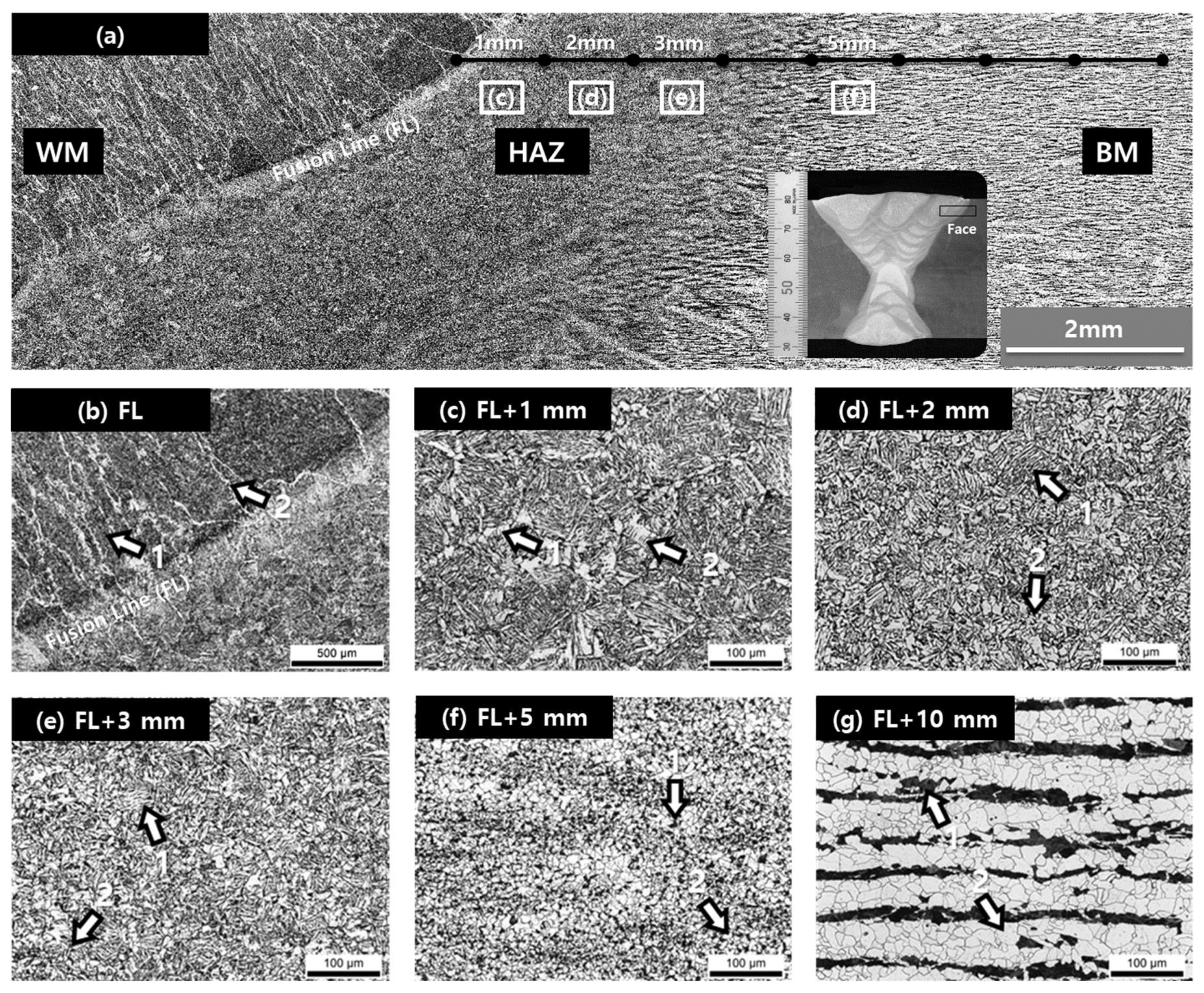
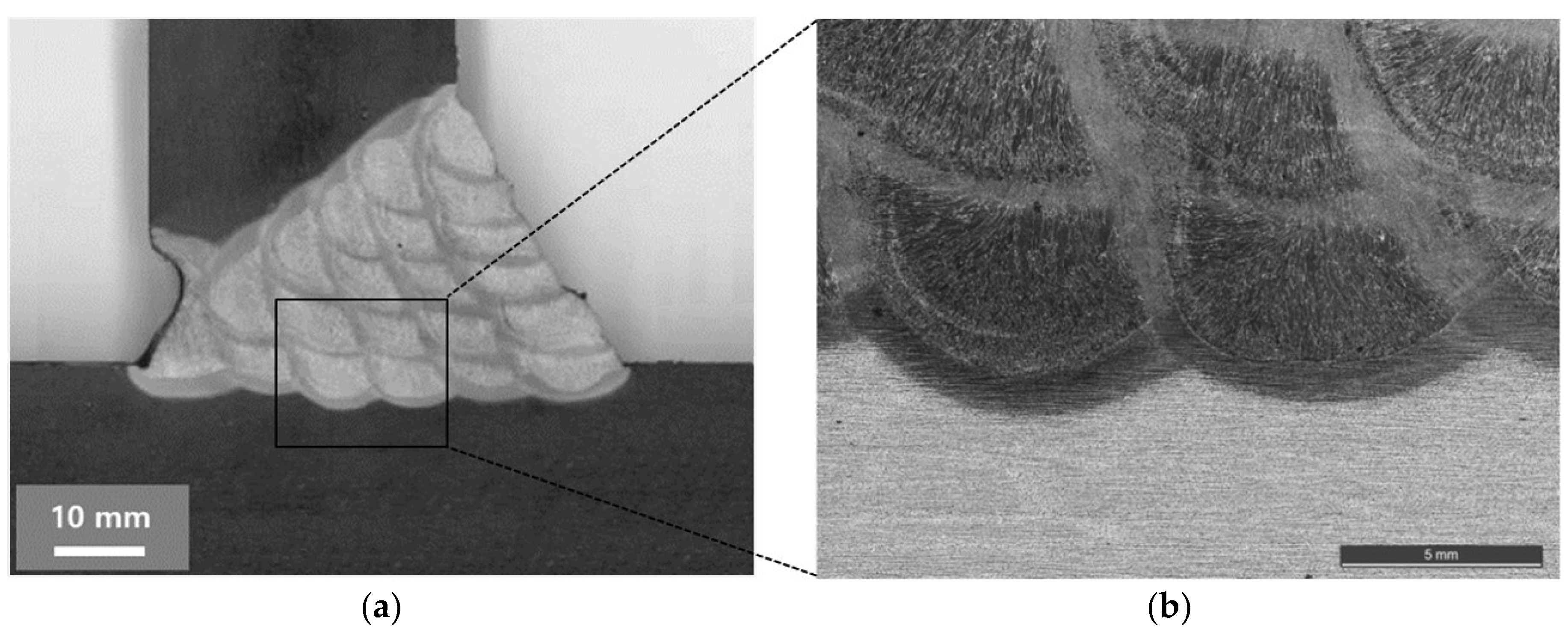
SN 490C plates, manufactured by controlled rolling were used in this study. The thicknesses of the plates were 30 and 70 mm, respectively. The FCAW and SAW processes were used to produce the weldment of the SN 490C. In case of the plate with 30 mm thickness, the type of the weld joint was single bevel grooved butt joint as shown in
Figure 1a.
The bevel angle was 35° and the width of the root gap was 8 mm. Welding was performed in the flat position (1G) with the conditions listed in
Table 1.
A flux cored wire, E71T-1C with a diameter of 1.4 mm, corresponding to AWS A5.20 [
27] was used. In the case of the plate with 70 mm thickness, the type of the weld joint was double V bevel grooved butt joint as shown in
Figure 1b. The bevel angles in the upper and lower grooves were 60° and 70°, respectively. The width of the root gap was 0 mm. Welding was performed in the flat position (1G) with the conditions shown in
Table 2.
A solid wire, EH14 with a diameter of 4.8 mm, corresponding to AWS A5.17 [
28] was used. The chemical composition of the E71T-1C and EH14 wires is listed in
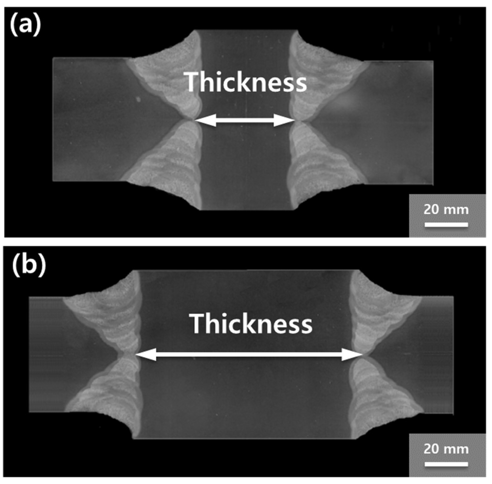
Table 3. The 30 mm thick weldments were manufactured with multi-layer welds of eight passes, and the 70 mm thick weldments were manufactured with multi-layer welds of 32 passes. Tensile test, bending test, hardness test, and toughness test were carried out for each weld. For the tensile test, uniaxial tensile tests were conducted using a universal testing machine (Z1200 of Zwick Roell company, Ulm, Germany). An extensometer was used for the study. For the bending test, in both 30 mm thick and 70 mm thick plates, test samples were machined to the width of 30 mm, the thickness of 30 mm, and length of 250 mm. The specimens were bent by a former with a diameter four times the thickness of the plates using a three-points bending machine.
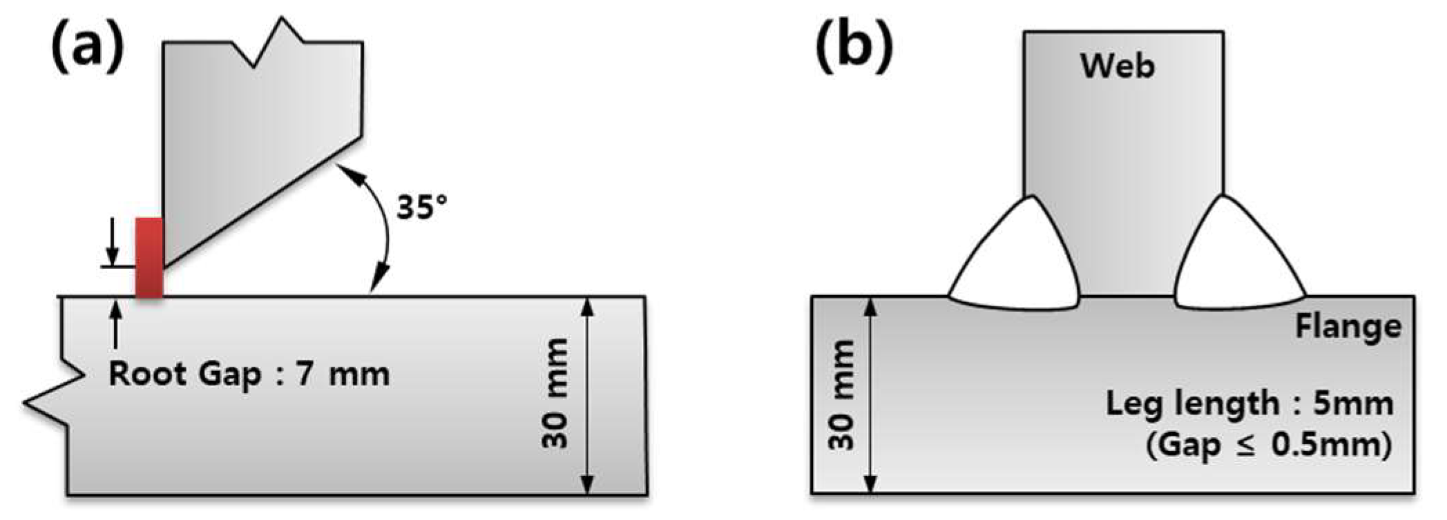
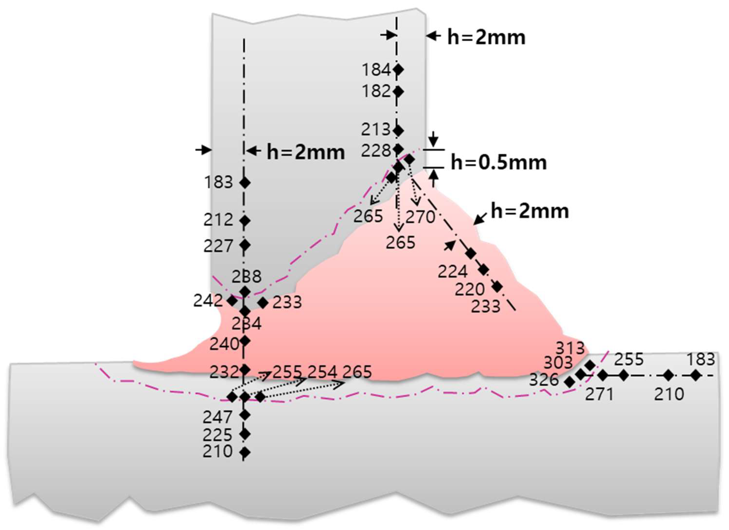
In addition to the butt joint weldment, T-joint weldments were also tested because the T-joint is often used in building structures. Two types of T-joint weldments were tested to evaluate the weldability of SN 490C. In the first case, a full-penetration weldment was produced in the horizontal (2G) position by an FCAW process. The shape of the weld joint was a single beveled T-joint as shown in
Figure 2a. The bevel angle was 35° and the width of root gap was 7 mm. In the second case, two partial-penetration weldments were produced in the horizontal (2F) position by an FCAW process. The shape of the weld joint is the double-fillet T-joint as shown in
Figure 2b. In each weldment, macro-examination and hardness tests were conducted.
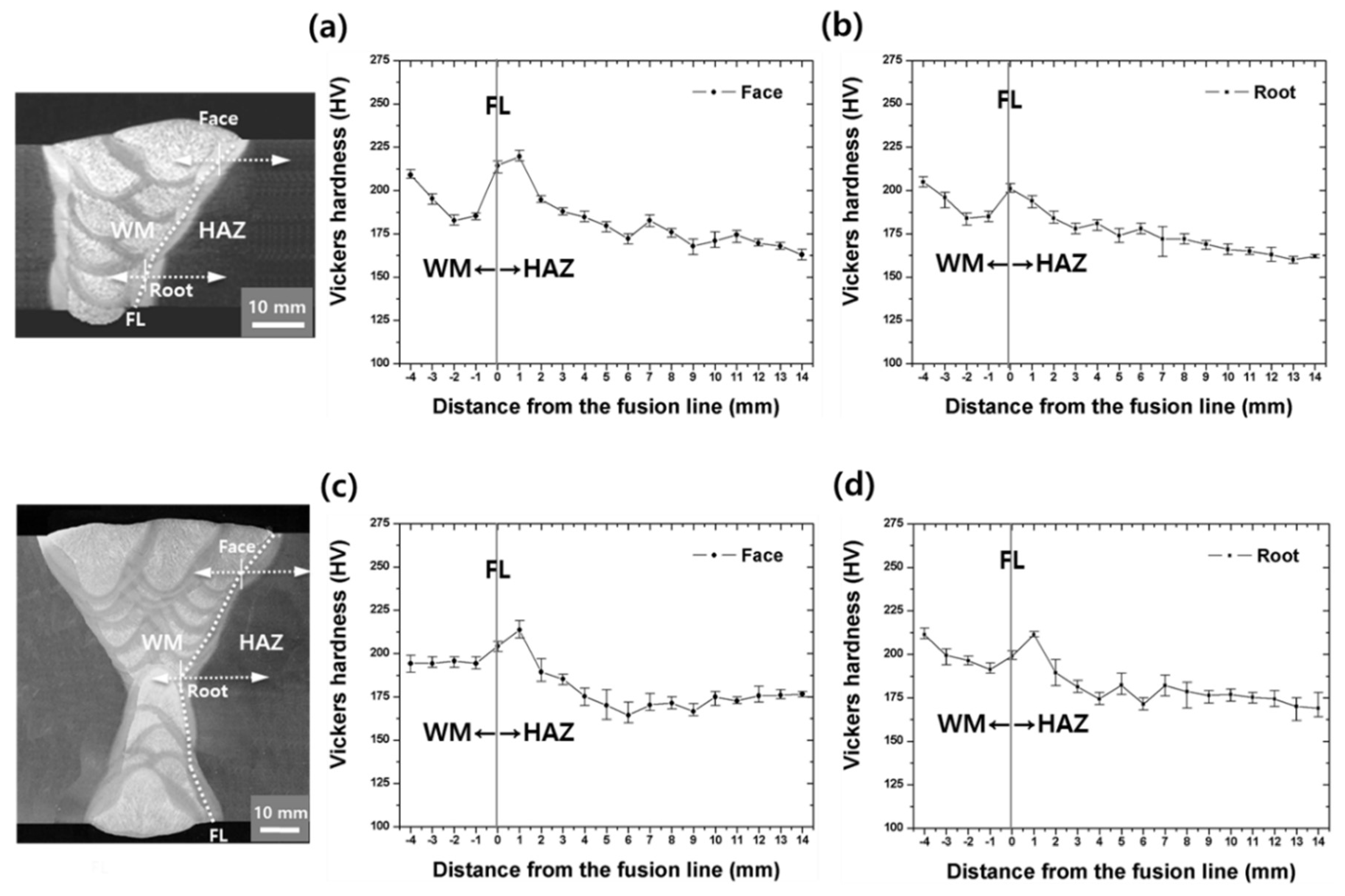
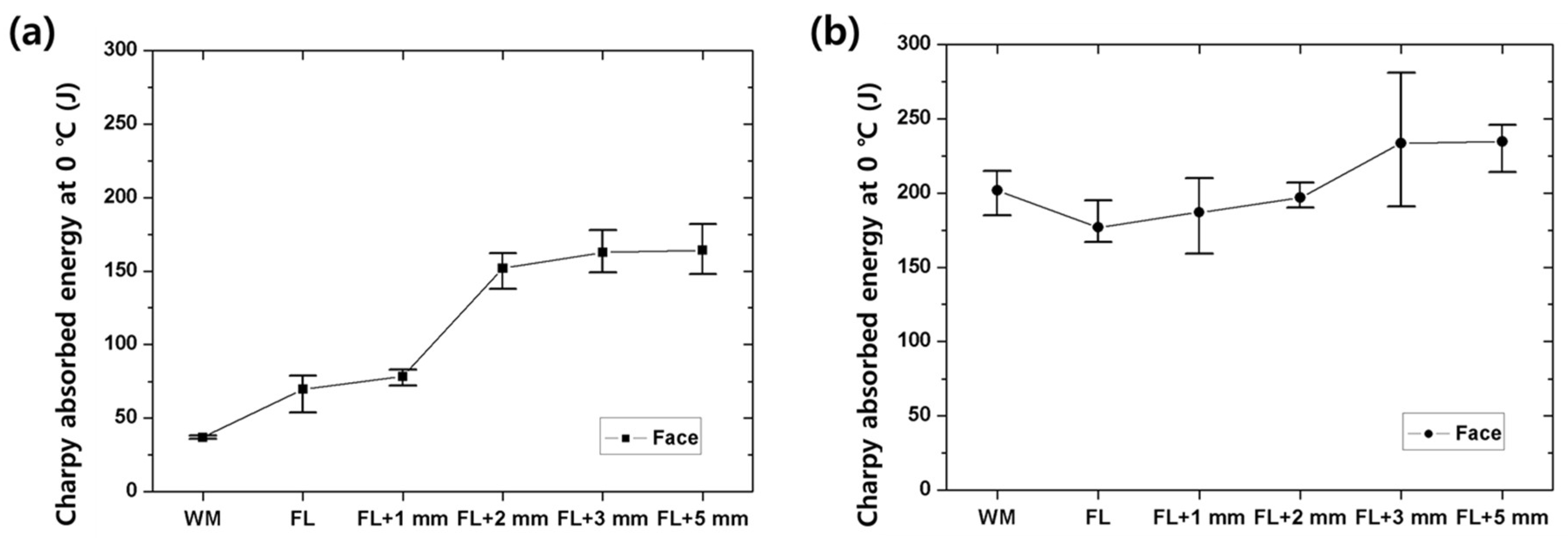
For a tensile test of the weldment, flat-shaped and round-shaped specimens were machined, according to ASTM A370. ASTM A370 includes how to produce the specimens for a tensile test, a guided bend test, and a Charpy V-notch impact test as well. Therefore, in order to conduct guided bend test for this weldment, face and root bend test specimens were produced according to ASTM A370. In addition, specimens of the Charpy V-notch impact test were produced according to ASTM A370. Once the specimens were ready, according to ASTM E8/E8M-13a, ASTM E190, ASTM E23, and ASTM E92, the tensile test, the guided bend test, the toughness test and the hardness test were conducted, respectively. All tests were conducted using the plates of thickness 30 and 70 mm. In this study, Z1200 of the Zwick Roell company was used for the tensile test and the guided bend test. PSW 1000 of the Zwick Roell company was used for the Charpy V-notch impact test. The average of Charpy absorbed energy was obtained as a result of three measurements at 0 °C. In the hardness test, the average of Vickers hardness was calculated as a result of three measurements at room temperature with a load of 0.98 N using a HV-114 (Mitutoyo, Kawasaki, Japan).
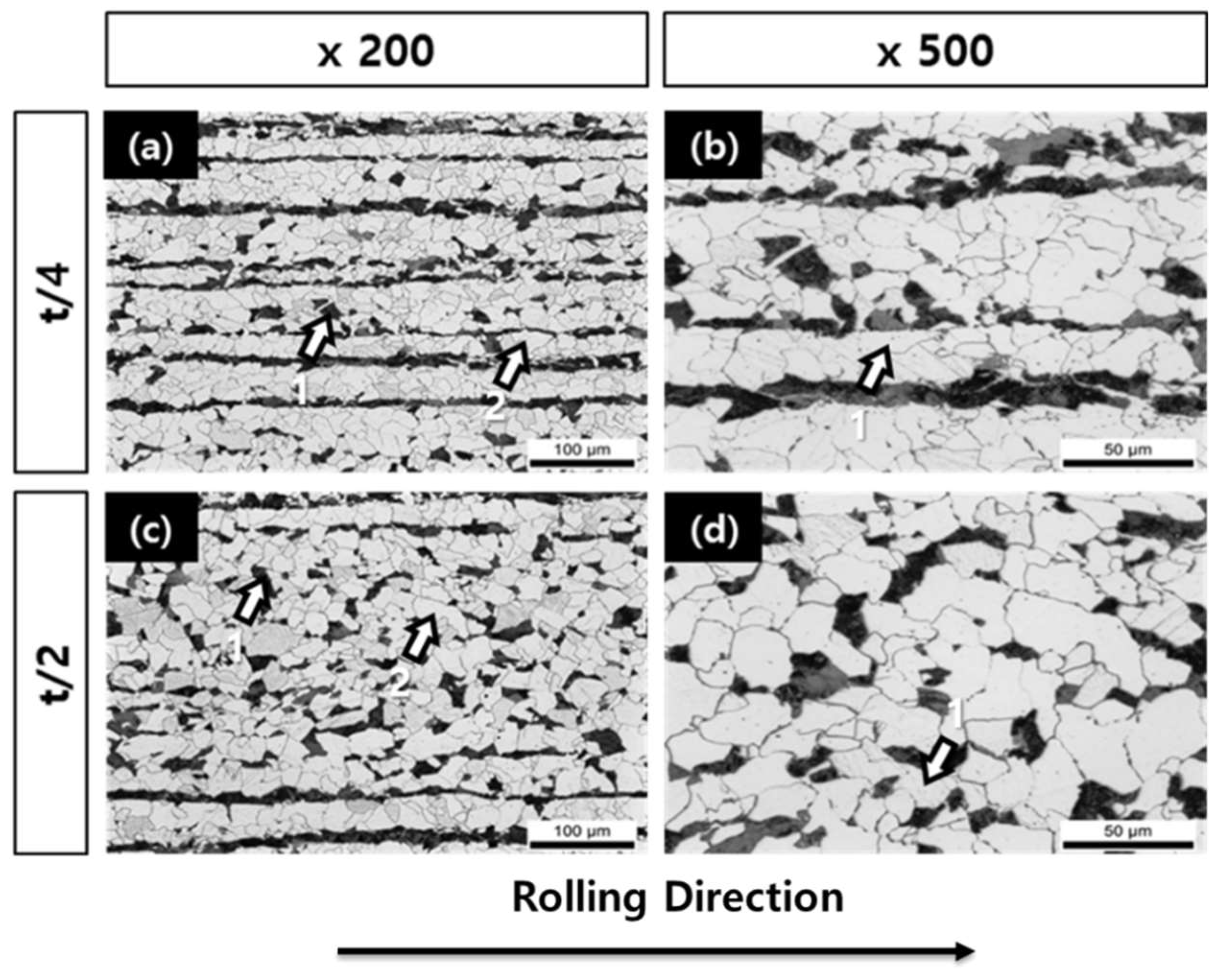
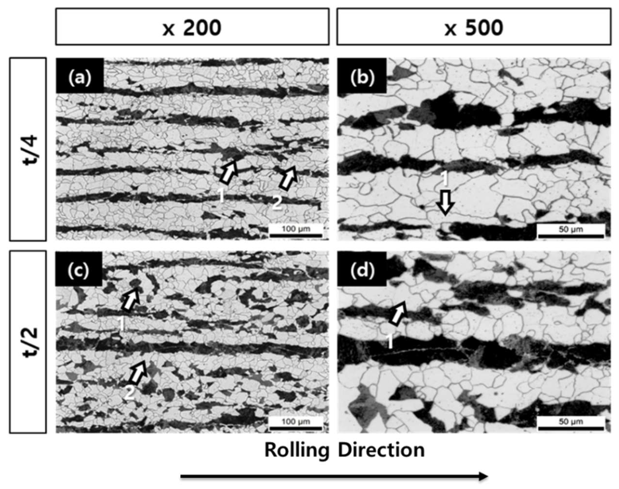
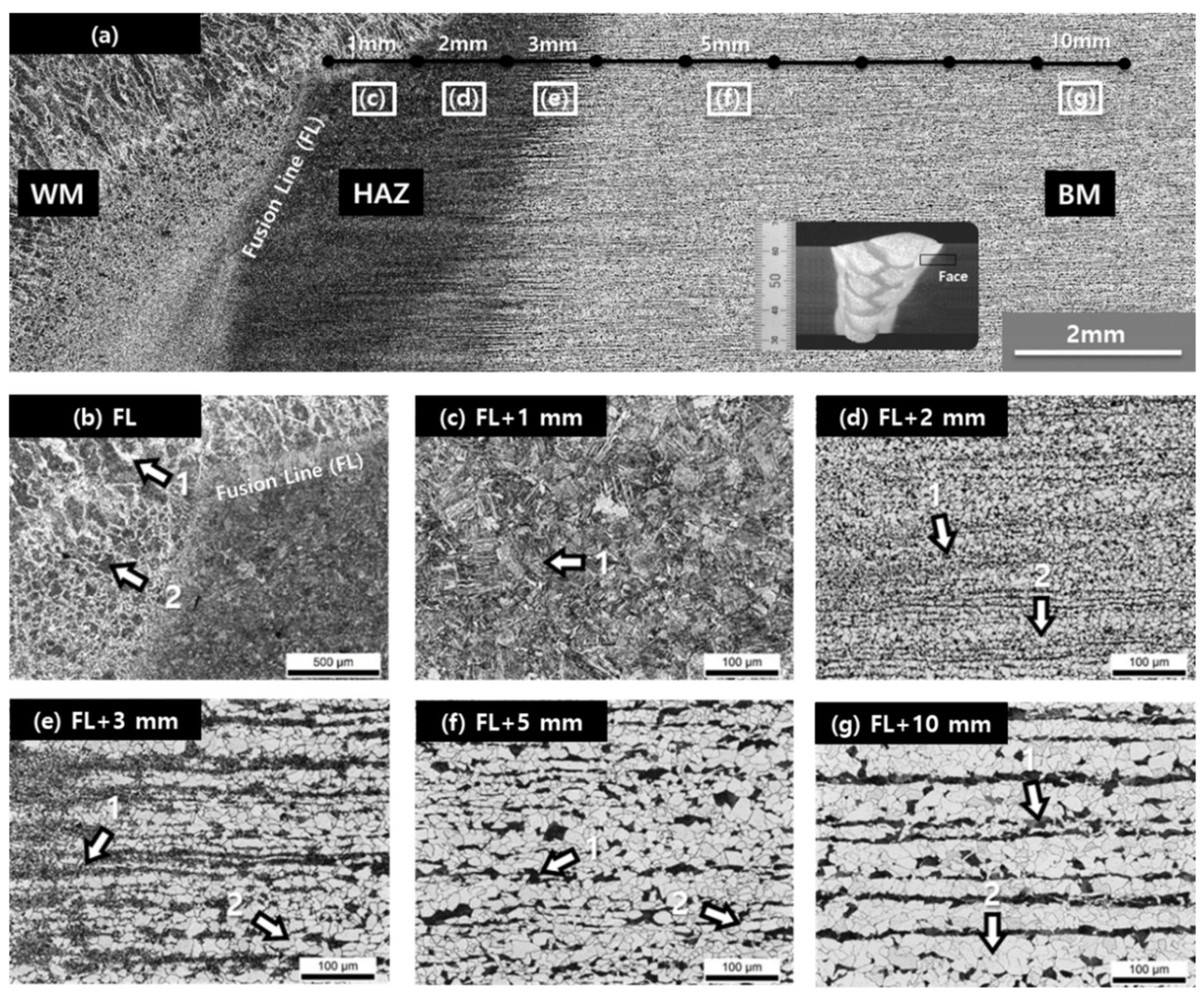
Polishing and machining of weldment were performed to observe the microstructure of the weldment [
29]. The weldment was then etched with 3% Nital (3% nitric acid + 97% ethanol) etchant. Using a Leica WBS-600AN optical microscope (Leica microsystems, Wetzlar, Germany), the microstructure of the weldment was observed.
Additionally, various tests were carried out to evaluate the lamellar tearing susceptibility of the base metal and the weldment. First, through-thickness tensile tests were conducted according to ASTM A770. Full-penetration welds were manufactured by FCAW and the window test was conducted. Partial-penetration welds were manufactured by FCAW and the Cranfield test was conducted.


