Article

The Effect of Hot-Mounting on the Microstructure of an As-Quenched Auto-Tempered Low-Carbon Martensitic Steel

1
Materials and Mechanical Engineering, Centre for Advanced Steels Research, University of Oulu, 90014 Oulun yliopisto, Finland
2
Kerttu Saalasti Institute, University of Oulu, Pajatie 5, FI-85500 Nivala, Finland
*
Author to whom correspondence should be addressed.
Metals 2019, 9(5), 550; https://doi.org/10.3390/met9050550
Submission received: 11 April 2019 / Revised: 4 May 2019 / Accepted: 9 May 2019 / Published: 11 May 2019

Abstract

:
The effect of hot-mounting for metallographic studies of as-quenched low-carbon martensitic steels has been studied. Hot-mounting is typically carried out at 150–200 °C, i.e., a low-temperature tempering regime. Cold- and hot-mounted specimens from an as-quenched low-carbon auto-tempered steel were examined using a scanning electron microscope and their hardness levels were also compared. It was found that hot-mounting causes additional tempering that manifests as the appearance of new precipitates in those regions that are free of auto-tempered cementite. The observations were rationalized using DICTRA simulations to calculate the potential growth of cementite. Hot-mounting was also shown to cause a small but statistically significant increase in the hardness of the martensite.

1. Introduction

High-strength steels are utilized in weight-critical structures to save energy and to decrease the carbon footprint through, for example, reduced fuel consumption in transport applications [1,2]. Low-carbon high-strength steels (<0.2 wt % C) are particularly important as structural steels as they have good weldability, unlike carbon-rich steels. Production lines involving reheating and subsequent quenching are the conventional way to produce high-strength steels [3]. Another approach to the production of tough high-strength steels is by the direct quenching process [1,2,3], where the quenching is integrated into the thermomechanical processing stage, avoiding the need for reheating the steel. The resultant microstructure of these steels is important as it determines the final mechanical properties. The morphology of as-quenched martensite in low-carbon steels is of the lath type [4,5,6,7]. The martensitic start (Ms) temperatures in low-carbon steels are high enough to promote tempering of martensite during the quenching—a phenomenon known as auto-tempering [6]. For auto-tempering to occur, carbon in solid solution in the martensitic matrix diffuses to, and precipitates at high-energy sites, such as dislocations [8]. Competing with this is the partitioning of carbon into the interlath regions which can stabilize the austenite to room temperatures [9]. Auto-tempering was found to improve the ductility by increasing the work-hardenability during straining of high-strength steels [3]. Auto-tempering was also found to improve the upper-shelf impact energy and lower the ductile to brittle transition temperature [10]. Electron microscopy is used for the characterization of auto-tempered carbides as they are not visible under conventional light optical microscopes.
In metallography, the specimen is cut, and the area of interest is ground and polished to remove the deformed layer and to attain a mirror-like finish. Finally, the polished specimen is etched with a suitable reagent to reveal the microstructure. Samples are usually mounted in a polymeric material before the grinding and polishing stage. One important advantage with mounting is that a flat surface can be maintained during grinding and polishing [11]. A flat surface is vital as it allows for easy scanning without changing the focus continuously in microscopes [11]. The mounting material can be classified broadly into two categories, namely, hot mounts and cold mounts. Hot-mounting is performed under a temperature and pressure cycle in a mounting press using thermosetting materials [11]. Cold-mounting is done by curing a castable mounting material around the specimen at room temperature. The curing process can take about a day. Thermosetting materials are widely used as the mounting operation is short, which is advantageous especially in a production metallographic laboratory [11].
In the case of high-carbon steel containing 1 wt % C, which is free of auto-tempering, it has been shown that the heat treatment involved in hot-mounting produces visible tempering effects [11]. However, in the case of as-quenched low-carbon martensitic steels that contain significant fractions of auto-tempered carbides, it might be expected that hot-mounting would not lead to any significant additional tempering if the carbon has already either precipitated as carbides or diffused into the interlath regions. This paper demonstrates that this is, in fact, not the case, and that the use of hot-mounting does indeed produce visible tempering effects that can cause incorrect electron microscopical characterization of the microstructure. In addition to this, atom probe tomography samples prepared from hot-mounted specimens could lead to inaccurate 3D imaging and chemical analyses. The experimental observations have been rationalized with the aid of Thermo-Calc and DICTRA (version 2017b, Thermo-Calc Software AB, Solna, Sweden) calculations [12]. Hardness tests were conducted and the results between the hot- and cold-mounted specimens were compared.

2. Materials and Methods

A low-carbon steel supplied in the form of 12 mm-thick hot-rolled plate, having the composition shown in Table 1, was used for the experiments. The bulk composition was determined using glow discharge optical emission spectroscopy (GDOES Spectruma GDA 750 Analyser) (Spectruma Analytik GmbH, Hof, Germany). Cylindrical specimens 6 mm in diameter and 9 mm in length, were machined from the plates with their long axes along the rolling direction. The specimens were austenitized and water-quenched using the Gleeble 3800 thermomechanical simulator (Dynamic Systems Inc., Poestenkill, NY, USA) as described by Ramesh Babu et al. [
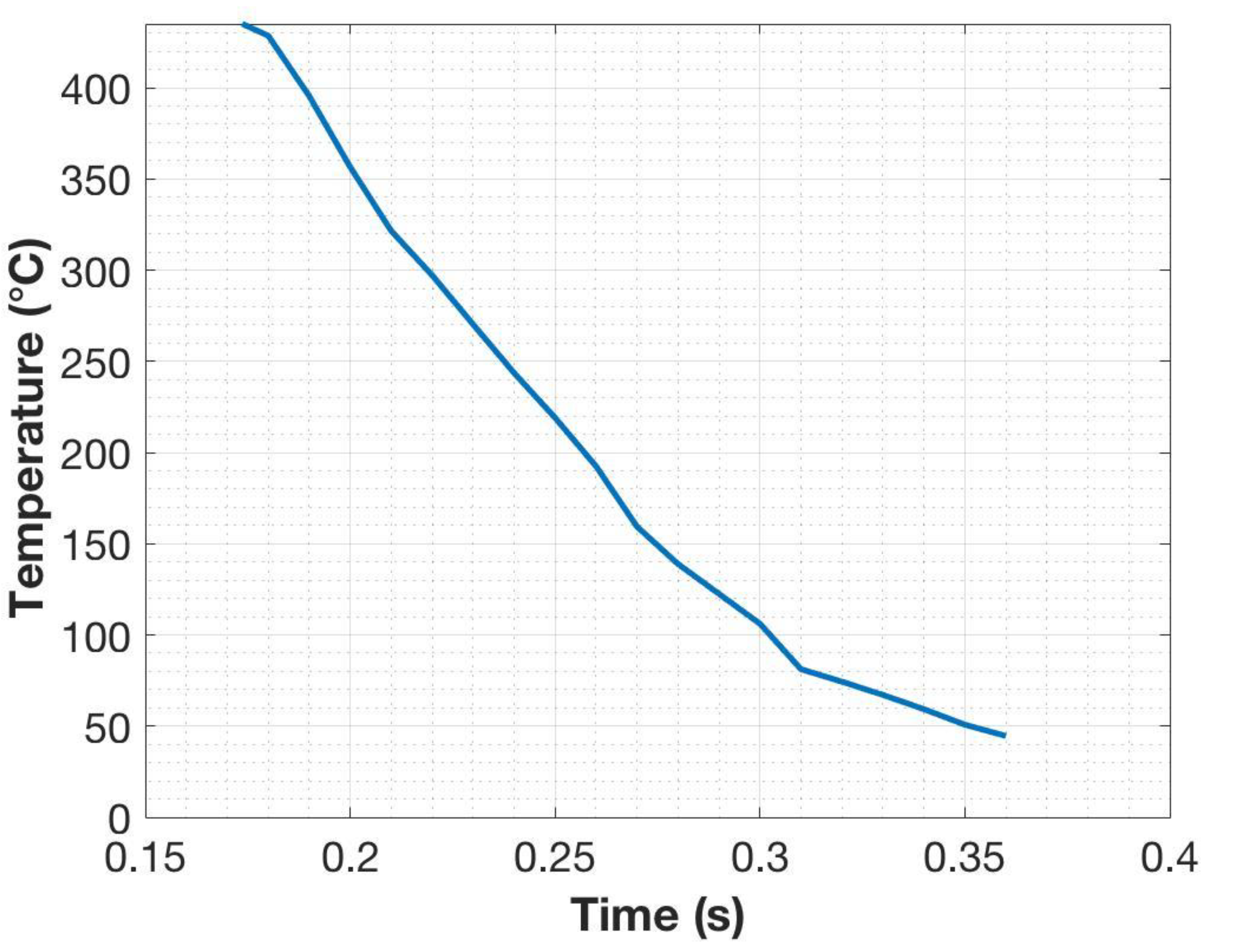
13]. The steel cylindrical specimens were held between two copper anvils located in massive aluminum jaws. Electric current passing through the specimen from the jaws generates the heating, and the temperature is controlled by a K-type thermocouple spot-welded onto the surface at the mid-length of the cylinder. The cylinders were heated at a rate of 10 °C/s to 950 °C held for 2 min to ensure austenitization, and then immediately quenched into a beaker of water below the anvils. The thermocouple data, as seen in Figure 1, revealed that the quenching rate was approximately 2000 °C/s after the Ms (435 °C). The cooling rate at the center of the specimen was calculated to be approximately 1000 °C/s using ELTA (version 6.0, NSG, St. Petersburg, Russia), which is a software designed for solving electromagnetic and thermal problems using a 1D finite difference method [14].
For field emission scanning electron microscopy (FE-SEM) analysis, cross sections from the heat-treated cylindrical specimens were cut transverse to the long axes of the cylinders at the position of the thermocouple. One set of the steel samples were molded into a conductive thermosetting hot-mounting plastic resin (Struers PolyFast) (Struers ApS, Ballerup, Denmark) in a Struers CitoPress-1 (Struers ApS, Ballerup, Denmark) machine using a pressure of 300 bar and a temperature of 180 °C for 4 min with subsequent water circulation cooling for 2 min. Another set of samples was cold-mounted with an epoxy resin (Struers EpoFix Resin) (Struers ApS, Ballerup, Denmark) mixed with a hardener (Struers EpoFix hardener) (Struers ApS, Ballerup, Denmark). It was cured and left to harden for 24 h. The mounted samples were ground, polished to a mirror finish using 0.04 µm colloidal silica, and subsequently etched with 2% Nital. Before etching, the samples were rinsed with water and ethanol to remove any remaining debris after the grinding and polishing stages. Microstructures were examined from the center of the specimens with a FE-SEM (Zeiss Sigma) (Carl Zeiss AG, Oberkochen, Germany) using 5 kV acceleration voltage and an InLens secondary electron detector.
Transmission electron microscopy (TEM) and scanning transmission electron microscopy (STEM) were used to characterize the precipitates present after quenching and mounting using a JEOL 2200FS STEM/TEM (JEOL Ltd., Akishima, Kantō, Japan) at an accelerating voltage of 200 kV. The samples were prepared using a FEI Helios DualBeam Focussed Ion Beam system (FEI Company, Hillsboro, OR, United States). A rough lamella (15 × 10 × 2 um3) was milled with a voltage of 30 kV and currents between 90 pA and 9 nA. The samples were then lifted using an OmniProbe and placed onto a copper grid. The lamella was then thinned and polished with an ion beam (30 kV at 90 pA and then at 5 kV at 44 pA) prior to TEM and STEM examination. STEM was used to image the surface of the sample and nanobeam selected area diffraction (NB-SAD) was used for identifying the precipitates. NB-SAD patterns and zone axis were verified using CrystBox (version 1.10, Institute of Physics of the Czech Academy of Sciences, Prague, Czech Republic) [15], which is an open source software for MATLAB (version 2018b, MathWorks, Inc, Natick, MA, United States). Each NB-SAD pattern was identified using the lattice parameters of either α-Fe (a = b = c = 2.860 Å) or cementite (a = 5.09 Å, b = 6.74 Å, c = 4.53 Å).
Hardness measurements were made using a Struers Duramin A300 hardness tester (Struers ApS, Ballerup, Denmark) with a Vicker’s indenter and a 10 kg load applied for 10 s. For statistical reliability, 20 measurements were done on both the hot- and cold-mounted specimen.

3. Results

Auto-tempered carbides can be seen distributed throughout the microstructures both in the cold- (Figure 2a) and hot-mounted (Figure 2b) specimens. In both cases, the size and number density of carbide precipitates varies from place to place. There are regions that appear relatively dark due to the fact that they contain a low area fraction of carbides resolvable in the SEM. However, comparing the two figures, the darker regions of the cold-mounted specimen show negligible to no precipitation. The dark regions in the hot-mounted specimen contain a denser distribution of precipitates compared to the cold-mounted specimens. Point counting revealed that roughly 10% of the martensite corresponds to the dark regions with negligible precipitation.
The auto-tempered precipitates were resolved in the STEM/TEM images (Figure 3), which shows that the precipitates in a coarse martensite lath are plate-like or rod-like with a crystal structure consistent with that of orthorhombic cementite; see the nanobeam diffraction patterns from the precipitate and the matrix in Figure 3c,d. No epsilon or Hägg carbides were found to be present.
Table 2 shows hardness values for the hot- and cold-mounted specimens. Using the software StatPlus [16], a standard two-tailed t-test was implemented to compare the values. The resulting p value 0.03855 (p < 0.05) showed, with 95% certainty, that there is a difference between the hardness values of the hot- and cold-mounted specimens (despite the overlapping of the 95% confidence intervals for the means). Hardness was slightly increased by the hot-mounting process.

4. Discussion

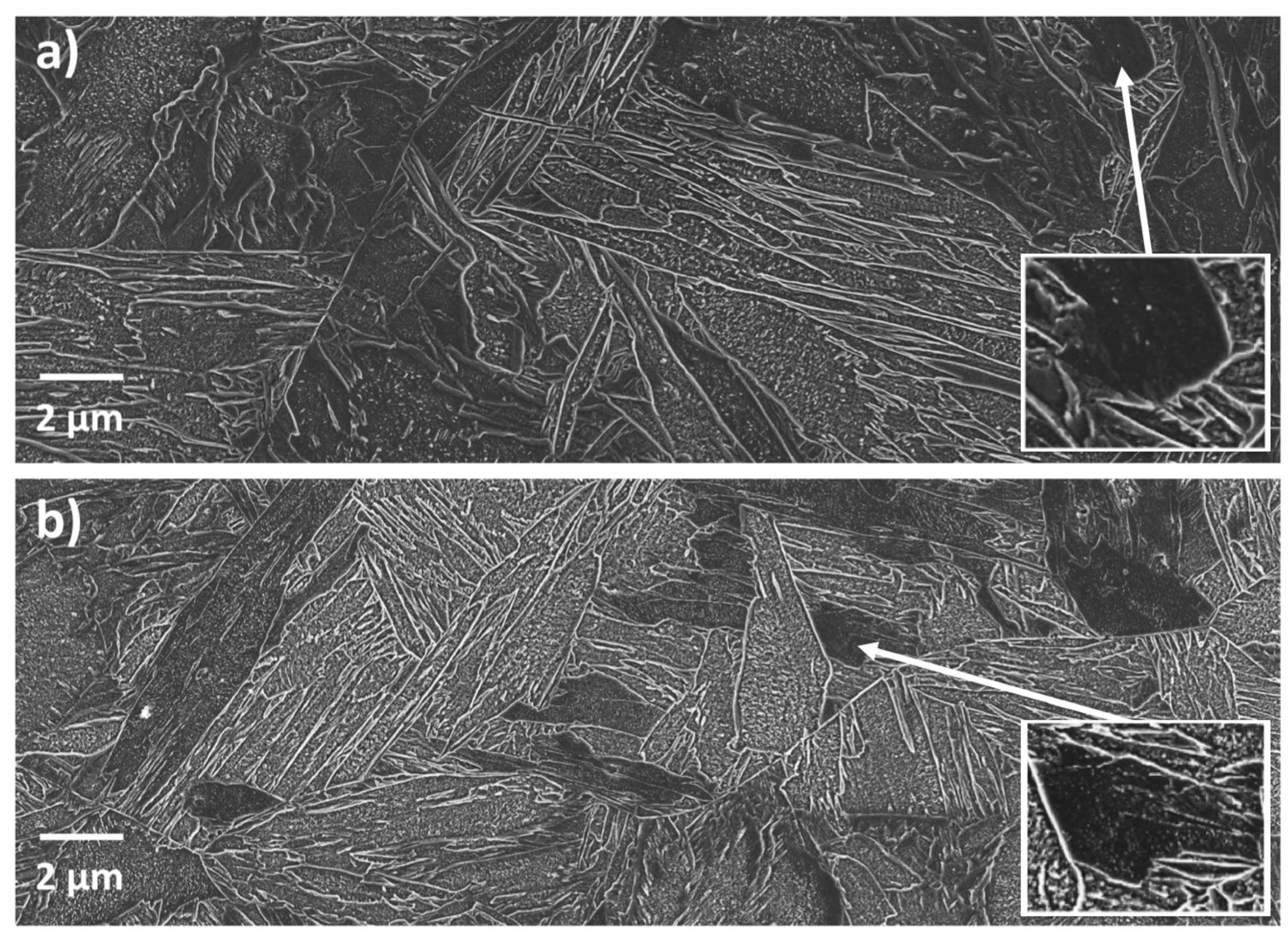
From the SEM micrographs in Figure 2, it can be seen that the martensite comprised both thin and thick laths with widths of around 0.5 µm and more than 1 µm, respectively. Such mixtures of coarse and fine laths are commonly found in as-quenched low-carbon steels, e.g., as shown by Morsdorf et al. [17,18], who suggested that the coarse laths are the first laths to form just below the Ms temperature, where the resistance to their growth into the austenite is small due to the effect of temperature on the strength of the austenite.
The high density of carbide precipitation in the coarse regions suggests that the auto-tempering process accompanies the early coarse martensite formation, which has transformed from austenite at temperatures just below Ms (435 °C). The TEM observations revealed that the rod- or plate-like precipitates are cementite. No epsilon or Hägg carbides were found in either the cold-mounted or hot-mounted specimens, even though tempering at 180 °C has sometimes been found to lead to the precipitation of epsilon carbide in steels with more than 0.2 wt % C [18]. The present finding agrees with the observations of Speich [19], i.e., that tempering martensite in steel containing less than 0.2 wt % C below 150 °C results in carbon segregation, whereas rod-shaped cementite or Hägg carbides form in the temperature range 150–400 °C.
A radial temperature gradient develops between the surface and the center due to the fast quenching conditions. As a result, the cooling rate is higher at the surface compared to the center of the specimen. The temperature gradient means that martensite forms first near the surface, but the auto-tempering at any location depends on the cooling rate after martensite starts to form and not on the temperature gradient. Despite the temperature gradient and variation of cooling rates through the cylinders, there were dark areas with negligible to no precipitation throughout the cold-mounted specimen, both near the center and the edge. In the hot-mounted specimens, the comparatively darker regions showed a discernible amount of precipitation throughout the specimen. Therefore, the effect of hot-mounting is due to the additional tempering and not due to a variation in the location of the areas studied.
DICTRA [12] calculations were made to qualitatively explore the potential growth of cementite precipitating in the martensite formed at various stages of the quenching process and any subsequent hot-mounting. To avoid convergence errors, a binary Fe–0.126% C system was selected. This approximation should not amount to significant errors as the early growth of cementite is expected to occur without appreciable diffusion of substitutional alloys [20,21]. The validity of using the binary approximation was also checked by making some calculations for the ternary Fe–0.126% C–1.66 Mn system as shown below. The simulation was set up as a closed cylindrical cell as seen in Figure 4. From the TEM observations (Figure 3) the distance between the cementite precipitates was approximately 100 nm. Therefore, the cementite was assumed to grow from the center of a cell surrounded by a ferrite matrix of radius 50 nm. The ferrite matrix was considered as it was the most suitable representation of the martensitic phase in DICTRA. It was pointed out by Bhadeshia [22] that the lattice diffusion in body-centered tetragonal (bct) ferrite is predicted to be slower than body-centered cubic (bcc) ferrite. After the formation of a martensite lath, the ferrite lattice may change from bct to bcc due to auto-tempering. On the other hand, the high dislocation density of martensite should increase the rate of diffusion due to more pipe diffusion than in ferrite. For these reasons, the DICTRA calculations can only be considered approximate. The cell was then discretized into a geometric series with the points being denser near the interface of the ferrite matrix. The simulation was run using a trapezoidal integration method. The Thermo-Calc [12] thermodynamic database TCFE9 and mobility database MOBFE2 was utilized. The initial composition of the ferrite matrix was assumed to be uniform at 0.126 wt % C. Upper-bound growth calculations were made by assuming that the precipitates nucleated with zero incubation time as soon as the martensite lath was formed, irrespective of the temperature. The calculations assume diffusion-controlled growth, i.e., local equilibrium across the cementite–ferrite interface and capillarity effects were ignored.
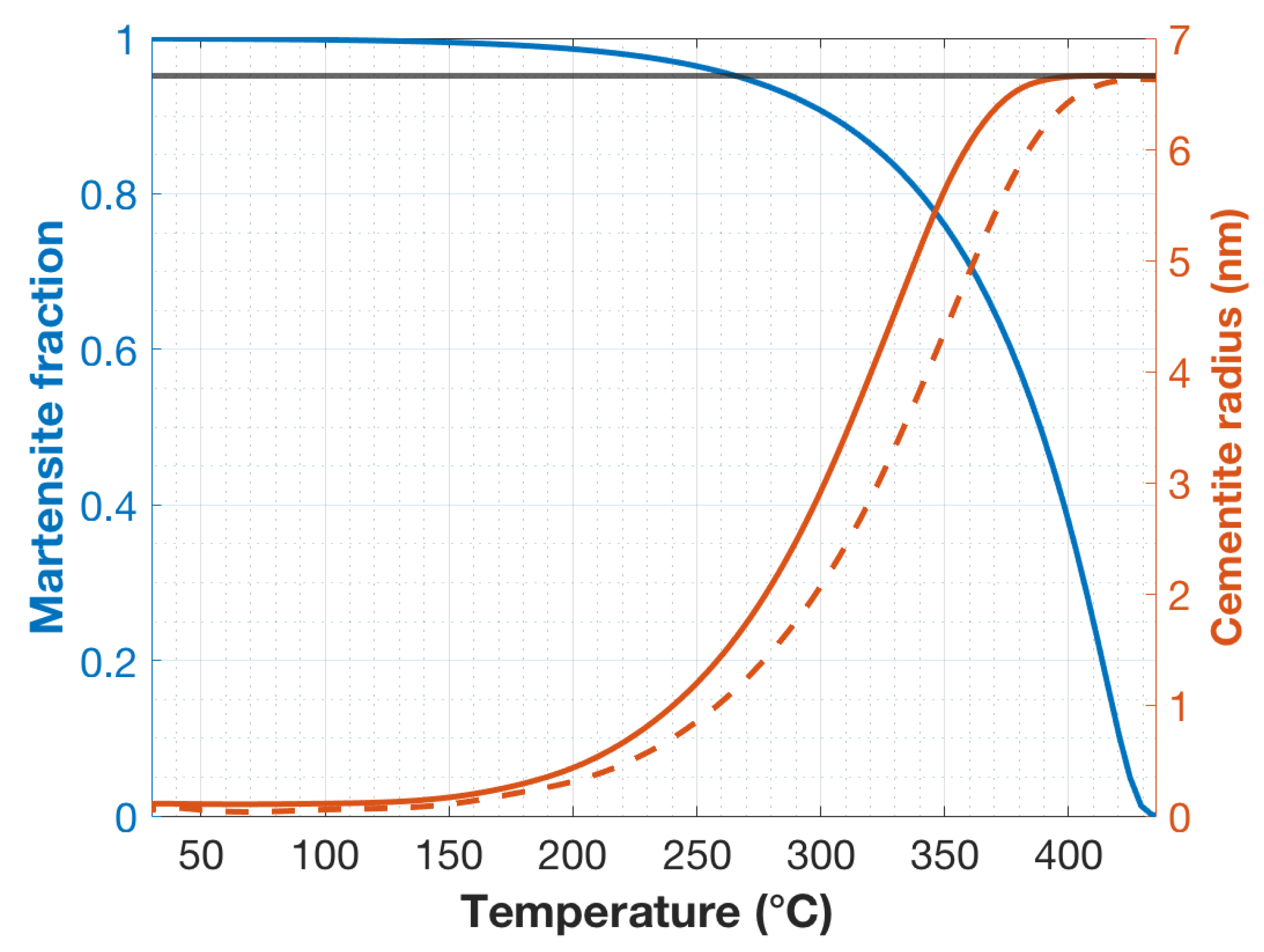
Figure 5 shows the calculated upper-bound radii of the cementite rods as a function of the martensite lath formation temperature and the volume fraction martensite for a cooling rate of 1000 and 2000 °C/s, which correspond to the cooling rates near the center and the surface of the specimens, respectively. These are, of course, upper-bound values, since it is assumed that incubation time is zero. Also, the inclusion of capillary effects would reduce the predicted initial growth rate by increasing the concentration of carbon in the ferrite at the interface with the cementite. Even at these high cooling rates and low temperatures, the high mobility of interstitial carbon should allow substantial growth of the cementite rods. In the first martensite formed at temperatures just under Ms, the cementite is predicted to grow to a radius of 6.66 nm after quenching to room temperature. It is interesting that the predicted radius is very close to the half-thickness of the cementite precipitate in the TEM image in Figure 3b. The predicted radius corresponds to a cementite volume fraction of 1.77% at the center and 1.76% at the edge of the specimen, which is close to the calculated equilibrium volume fraction at room temperature of 1.93%. As expected, the cementite precipitating in laths formed at temperatures lower than Ms have smaller radii. The simulations with the Fe–C–Mn system for laths formed at Ms and at 260 °C gave almost identical cementite radii as the calculations for the binary Fe–C system: the final radius of the cementite precipitated in laths formed at Ms was 6.65 nm for the Fe–C–Mn calculations and 6.66 nm for the Fe–C calculations. For laths forming at 260 °C, the final radius was 1.50 nm for the Fe–C–Mn system and 1.44 nm for the binary system. Therefore, it appears that the introduced errors are probably very small when ignoring the effects of alloying elements other than carbon.
Another set of DICTRA simulations was run with an additional thermal cycle simulating the hot-mounting (180 °C for 4 min). The result was that cementite precipitated at any temperature during quenching grew to a radius of 6.66 nm. The simulation results, therefore, show that the hot-mounting thermal cycle can cause sufficient diffusion of carbon to enable almost the full precipitation of the equilibrium volume fraction of cementite around pre-existing precipitates or nuclei on the assumption that the distance between the cementite rods is of the order of 100 nm.
The negligibly tempered regions in the cold-mounted SEM micrographs, as seen in the Figure 2a, amounted to roughly 10% of the microstructure. Correspondingly, as seen in Figure 5, the last 10% of the transformation of martensite occurs below the temperature of 300 °C. From the DICTRA calculations, the maximum of carbide radii precipitating below 300 °C is less than 3 nm at the center of the specimen and less than 2 nm near the edge of the specimen. Although a few carbides of these dimensions could be seen in the darker regions of the martensite, these regions mostly appeared to contain no resolvable precipitates. This could also be an indication that the DICTRA-calculated radius are upper-bound values. Especially as the lath formation temperature drops ever further below Ms, the actual sizes might become much smaller than the upper-bound dimensions. Notwithstanding the above reasoning, it is an experimental fact that hot-mounting changes the appearance of the dark precipitate-free regions of the auto-tempered martensite, and the diffusion calculations show that the thermal cycle associated with hot-mounting can indeed lead to significant carbide growth.
The hardness results (Table 2) also show that there is a small but statistically significant increase in the measured martensite hardness as a result of hot-mounting. The explanation for this is beyond the scope of this paper, but it is an important fact to bear in mind when investigating the mechanical properties of martensite.

5. Summary

This paper explored the effect of hot-mounting (180 °C for 4 min) on the microstructure of as-quenched, martensitic, (0.126 wt % C) low-carbon steel containing auto-tempered carbides visible in FE-SEM images after etching with 2% Nital. It was shown that there is a clear effect of hot-mounting on the apparent distribution of auto-tempered cementite carbides due to the additional low-temperature tempering resulting from the hot-mounting stage. In cold-mounted specimens, regions free of auto-tempered carbides are seen, whereas after hot-mounting, precipitates appear in these regions. Additionally, hot-mounting causes a small, but statistically significant, increase in the measured martensite hardness. The feasibility of significant cementite growth during the hot-mounting process can be rationalized on the basis of carbon diffusion kinetics. DICTRA simulations also show that after quenching, the hot-mounting profile can cause the diffusion of almost all carbon in the ferrite into the cementite, thereby promoting its growth.

Author Contributions

Writing—original draft, S.R.B.; writing—review and editing, M.J., A.J., D.P.; supervision, D.P.

Funding

The authors are grateful for financial support from the European Commission under grant number 675715-MIMESIS- H2020-MSCA-ITN-2015, which is a part of the Marie Sklodowska-Curie Innovative Training Networks European Industrial Doctorate Programme.

Acknowledgments

The authors would like to thank Juha Uusitalo and Tun Tun Nyo from the University of Oulu for their support with regards to the dilatometry experiments. The authors thank Esa Heinonen and Sami Saukko for their support with regards to FIB and TEM work. The authors thank Dmitry Ivanov from EFD Induction AS, Norway for his support with regards to calculations using ELTA. The authors would also like to thank Pasi Suikkanen from SSAB Europe Oy for his support. The support of SSAB Europe Oy in providing the steel studied is also acknowledged.

Conflicts of Interest

The authors declare no conflict of interest.

References

  1. Jukka, K.; Karjalainen, P.; Porter, D. Direct-Quenched Structural Steels. In Encyclopedia of Iron, Steel, and Their Alloys; Totten, G.E., Colas, R., Eds.; CRC Press: Boca raton, FL, USA, 2016; ISBN 1-4665-1104-4. [Google Scholar]
  2. Speer, J.G.; Matlock, D.K. Recent developments in low-carbon sheet steels. JOM 2002, 54, 19–24. [Google Scholar] [CrossRef]
  3. Matsuda, H.; Mizuno, R.; Funakawa, Y.; Seto, K.; Matsuoka, S.; Tanaka, Y. Effects of auto-tempering behaviour of martensite on mechanical properties of ultra high strength steel sheets. J. Alloys Compd. 2013, 577, S661–S667. [Google Scholar] [CrossRef]
  4. Ping, D.H.; Guo, S.Q.; Imura, M.; Liu, X.; Ohmura, T.; Ohnuma, M.; Lu, X.; Abe, T.; Onodera, H. Lath formation mechanisms and twinning as lath martensite substructures in an ultra low-carbon iron alloy. Sci. Rep. 2018, 8, 1–11. [Google Scholar] [CrossRef] [PubMed]
  5. Krauss, G. Steels: Heat treatment and proceesing principles; ASM International: Geauga County, OH, USA, 1990. [Google Scholar]
  6. Bhadeshia, H.K.D.H.; Honeycombe, R.W.K. Steels: Microstructure and Properties, 4th ed.; Butterworth-Heinemann: Oxford, UK, 2017. [Google Scholar]
  7. Kitahara, H.; Ueji, R.; Tsuji, N.; Minamino, Y. Crystallographic features of lath martensite in low-carbon steel. Acta Mater. 2006, 54, 1279–1288. [Google Scholar] [CrossRef]
  8. Hutchinson, B.; Hagström, J.; Karlsson, O.; Lindell, D.; Tornberg, M.; Lindberg, F.; Thuvander, M. Microstructures and hardness of as-quenched martensites (0.1–0.5%C). Acta Mater. 2011, 59, 5845–5858. [Google Scholar] [CrossRef]
  9. Speer, J.; Matlock, D.K.; De Cooman, B.C.; Schroth, J.G. Carbon partitioning into austenite after martensite transformation. Acta Mater. 2003, 51, 2611–2622. [Google Scholar] [CrossRef]
  10. Li, C.N.; Yuan, G.; Ji, F.Q.; Ren, D.S.; Wang, G.D. Effects of auto-tempering on microstructure and mechanical properties in hot rolled plain C-Mn dual phase steels. Mater. Sci. Eng. A 2016, 665, 98–107. [Google Scholar] [CrossRef]
  11. Bramfitt, B.L.; Benscoter, A.O. Metallographer’s: Guide Practices and Procedures for Irons and Steels; ASM International: Geauga County, OH, USA, 2001; ISBN 0871707489. [Google Scholar]
  12. Andersson, J.O.; Helander, T.; Höglund, L.; Shi, P.; Sundman, B. Thermo-Calc & DICTRA, computational tools for materials science. Calphad 2002, 26, 273–312. [Google Scholar]
  13. Ramesh Babu, S.; Ivanov, D.; Porter, D. Influence of Microsegregation on the Onset of the Martensitic Transformation. ISIJ Int. 2018, 59, 169–175. [Google Scholar] [CrossRef]
  14. Bukanin, V.; Zenkov, A.; Ivanov, A. Design of induction heating devices using ELTA and 2DELTA software. In Proceedings of the 2016 IEEE North West Russia Section Young Researchers in Electrical and Electronic Engineering Conference (2016 EIConRusNW), St. Petersburg, Russia, 2–3 February 2016. [Google Scholar]
  15. Klinger, M.; Jäger, A. Crystallographic Tool Box (CrysTBox): Automated tools for transmission electron microscopists and crystallographers. J. Appl. Crystallogr. 2015, 48, 2012–2018. [Google Scholar] [CrossRef] [PubMed]
  16. StatPlus:mac—statistical analysis program for macOS®, version 6; AnalystSoft Inc.: Walnut, CA, USA, 2019.
  17. Morsdorf, L.; Tasan, C.C.; Ponge, D.; Raabe, D. 3D structural and atomic-scale analysis of lath martensite: Effect of the transformation sequence. Acta Mater. 2015, 95, 366–377. [Google Scholar] [CrossRef]
  18. Morsdorf, L.; Jeannin, O.; Barbier, D.; Mitsuhara, M.; Raabe, D.; Tasan, C.C. Multiple mechanisms of lath martensite plasticity. Acta Mater. 2016, 121, 202–214. [Google Scholar] [CrossRef]
  19. Speich, G.R. Tempering of Low-Carbon Martensite. Trans. Met. Soc. AIME 1969, 245, 2553–2564. [Google Scholar]
  20. Klein, S.; Mujica Roncery, L.; Walter, M.; Weber, S.; Theisen, W. Diffusion processes during cementite precipitation and their impact on electrical and thermal conductivity of a heat-treatable steel. J. Mater. Sci. 2017, 52, 375–390. [Google Scholar] [CrossRef]
  21. Hou, Z.; Hedström, P.; Xu, Y.; Di, W.; Odqvist, J. Microstructure of Martensite in Fe–C–Cr and its Implications for Modelling of Carbide Precipitation during Tempering. ISIJ Int. 2014, 54, 2649–2656. [Google Scholar] [CrossRef] [Green Version]
  22. Bhadeshia, H.K.D.H. Carbon in cubic and tetragonal ferrite. Philos. Mag. 2013, 93, 3714–3725. [Google Scholar] [CrossRef]
Figure 1. Thermocouple data obtained from the surface of the specimen during quenching of the steel after austenitizing with the Gleeble.
Metals 09 00550 g001
Figure 2. Scanning Electron Microscopy (SEM) secondary electron micrographs of specimens austenitized and quenched in the Gleeble: (a) cold-mounted (b) hot-mounted. Insets are magnified images of areas showing the least auto-tempering. Both images were obtained from the centers of transverse cross sections through the specimens.
Metals 09 00550 g002
Figure 3. Transmission and Scanning transmission electron microscopy (TEM/STEM) micrographs of hot-mounted specimens austenitized and quenched in the Gleeble. (a) STEM image of cementite precipitates in a coarse martensite lath; (b) TEM image of cementite precipitate, where yellow dots mark the location of nanobeam selected area diffraction (NB-SAD) patterns; (c) NB-SAD pattern with cementite diffraction spots indexed, zone axis [110]; (d) NB-SAD pattern with ferrite matrix spots indexed, zone axis close to [111].
Metals 09 00550 g003
Figure 4. Schematic of the 2D simulation setup used in DICTRA wherein cementite with a radius of 0.1 nm was assumed to be located at the center of a ferrite cylinder of radius of 50 nm.
Metals 09 00550 g004
Figure 5. Martensite fraction vs. temperature, until room temperature, as shown with a blue line. The evolution was based on the Koistinen–Marburger equation in combination with electron probe microanalyses of local chemical compositions. The methodology is explained in Ramesh Babu et al. [13]. The predicted upper-bound radius of cementite precipitated in martensite laths formed at various temperatures through the quenching process is shown with orange lines. The solid orange line represents the radius of cementite near center of the specimen where the cooling rate was about 1000 °C/s. The dashed orange line represents the radius of cementite formed near the edge of the specimen where the cooling rate was about 2000 °C/s. The black line represents the predicted radius of cementite after the hot-mounting stage.
Metals 09 00550 g005
Table 1. Mean chemical composition (wt %) (Spectruma GDA 750 Analyzer) of the steel.
CSiMnCrNiTiVAl
0.1260.721.660.270.0380.0270.0470.054
Table 2. HV10 hardness after hot- and cold-mounting.
MountingHotCold
Mean443.65432.55
Standard deviation16.7116.03
Number of measurements2020
Lower 95% confidence limits for the mean435.83425.05
Upper 95% confidence limits for the mean451.47440.05

