Communication

Feasibility Study on Application of Synchrotron Radiation μCT Imaging to Alloy Steel for Non-Destructive Inspection of Inclusions

1
Department of Mechanical Engineering, Shizuoka University, Shizuoka 432-8561, Japan
2
Hitachi Construction Machinery Co., Ltd., Tokyo 110-0015, Japan
3
Department of Mechanical Systems Engineering, Tokyo City University, Tokyo 158-8557, Japan
4
Japan Atomic Energy Agency, Hyogo 679-5148, Japan
5
National Institutes for Quantum and Radiological Science and Technology, Hyogo 679-5148, Japan
*
Author to whom correspondence should be addressed.
Metals 2019, 9(5), 527; https://doi.org/10.3390/met9050527
Submission received: 15 April 2019 / Revised: 4 May 2019 / Accepted: 5 May 2019 / Published: 8 May 2019
(This article belongs to the Special Issue Fracture, Fatigue and Structural Integrity of Metallic Materials)

Abstract

:
In order to examine the feasibility of applying synchrotron radiation μCT imaging to alloy steels for non-destructive inspection of inclusions for potential origins of internal fatigue damage in the very high cycle region, synchrotron radiation μCT imaging was utilized for repeated non-destructive observation of Cr-Mo steel. An ultrasonic fatigue testing machine was used in aid of the repeated observation. As a result, it was found that the synchrotron radiation μCT imaging with 70 keV was useful for non-destructive observation of inclusions of more than 10 μm, one of which may be an internal fatigue origin. No identifiable damage was observed around every inclusion, and in the base metal, at least up to 70% of fatigue life was observed in the imaging volume.

Graphical Abstract

1. Introduction

Alloy steels may suffer from a fatigue fracture called a “Giga cycle fatigue” or a “Very high cycle fatigue,” which is a fatigue phenomenon as a result of cyclic loading in excess of 107 cycles. The fatigue fracture in the very high cycle region often originates from an inclusion such as metallic oxide. A small, dark area, whose diameter is a few 10 μm, is observed around the inclusion when optical microscopy is used, and a fine granular fracture surface was observed in the dark area if scanning electron microscopy is used. The circular area is referred to as a “fish eye” [1], and the dark area in the center of a fish eye is referred to as “optical dark area (ODA)” [2] or “Fine granular area (FGA)” [3]. In this study, we use a terminology “ODA” to indicate the area. The diameter of ODA is a few tens μm.
It has been suggested [4,5,6] that the nucleation and the formation of ODA consume most of the fatigue life for an internal fatigue fracture. Thus, it is important to elucidate the mechanism of nucleation and the formation process of ODA. Several experimental papers [4,5,6] have been reported for tackling with the problem. Kuroshima et al. [4] conducted elaborative experiments in which specimens subjected to cyclic loading were cut and polished until inclusions were found, and concluded that penny-shaped microcracks around many inclusions nucleated in the early stage of very high cycle fatigue of Cr-Mo steel, but the propagation of the microcracks was very slow and the size of the microcracks slightly increased just before fatigue failure. Lu and Shiozawa [5] and Ogawa et al. [6] measured the crack growth rate of internal fatigue crack of high C-Cr spring steel by using a beach mark technique and concluded that the crack growth rate in ODA was extremely slow compared to that of surface cracks. For titanium alloys, internal fatigue fracture in the very high cycle region can be seen [7,8]. Yoshinaka [7] reported non-destructive observation of internal fatigue crack nucleation and propagation of Ti-6Al-4V by using synchrotron radiation μCT imaging. However, to the best of our knowledge, there are no results in the literature regarding non-destructive observation of nucleation and propagation of the ODA of ferrous alloys. Therefore, synchrotron radiation μCT imaging was used in this study for the non-destructive observation of Cr-Mo steel subjected to fatigue loading up to 108 cycles.
Synchrotron radiation μCT imaging is a micro computed tomography imaging technique that uses high energy X-ray of about 100 keV available in synchrotron radiation facilities, and a high spatial resolution on the order of μm can be achieved even if the target material is a heavy metal such as Fe [9]. In this study, SPring-8 in Hyogo, Japan was used, which is one of the largest third-generation synchrotron facilities. Since the available time of a beamline in SPring-8 was limited to within 48 h, an ultrasonic fatigue testing machine with the cyclic frequency of 20 kHz was used to exert fatigue loading on site, allowing us to conduct repeated μCT imaging of an identical specimen from an intact condition, i.e., before applying cyclic loading, to fatigue-loaded conditions up to 108 cycles within 48 h.
The aim and novelty of the present work are to examine the feasibility of non-destructive inspection of inclusions, one of which may be an internal fatigue origin site, and to examine the feasibility of detection of internal fatigue damage, i.e., fatigue crack nucleation and progress, in alloy steels using synchrotron radiation μCT imaging in aid of an ultrasonic fatigue testing technique for reducing fatigue testing periods on site. In addition, the fatigue strength was compared with the prediction using the Vickers hardness and inclusion size, the so-called Murakami’s approach [10], to confirm the effect of the strain rate on the fatigue strength in this study.

2. Material and Methods

2.1. Material

Cr-Mo steel, JIS SCM420H, was used. The chemical composition is shown in Table 1. Specimens were annealed at 900 °C for 45 min, oil quenched, and tempered at 180 °C for 120 min. The proof stress was about 850 MPa, the tensile strength was about 1200 MPa, and the Vickers hardness was 435 Hv. The specimen’s surface was mirror finished after heat treatment to minimize the influence of surface roughness on the quality of radiographs.

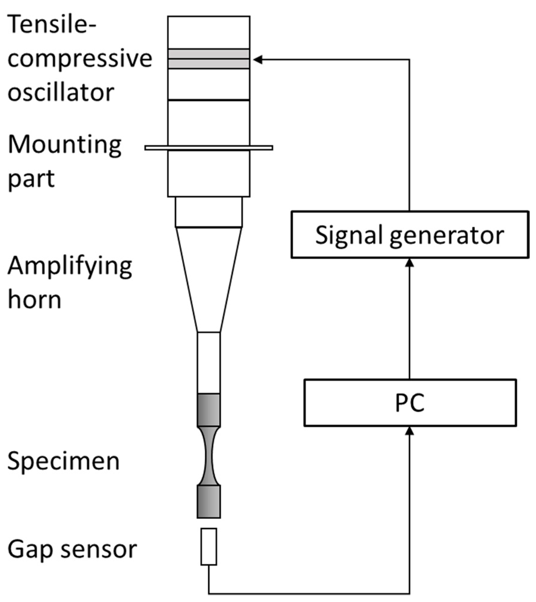
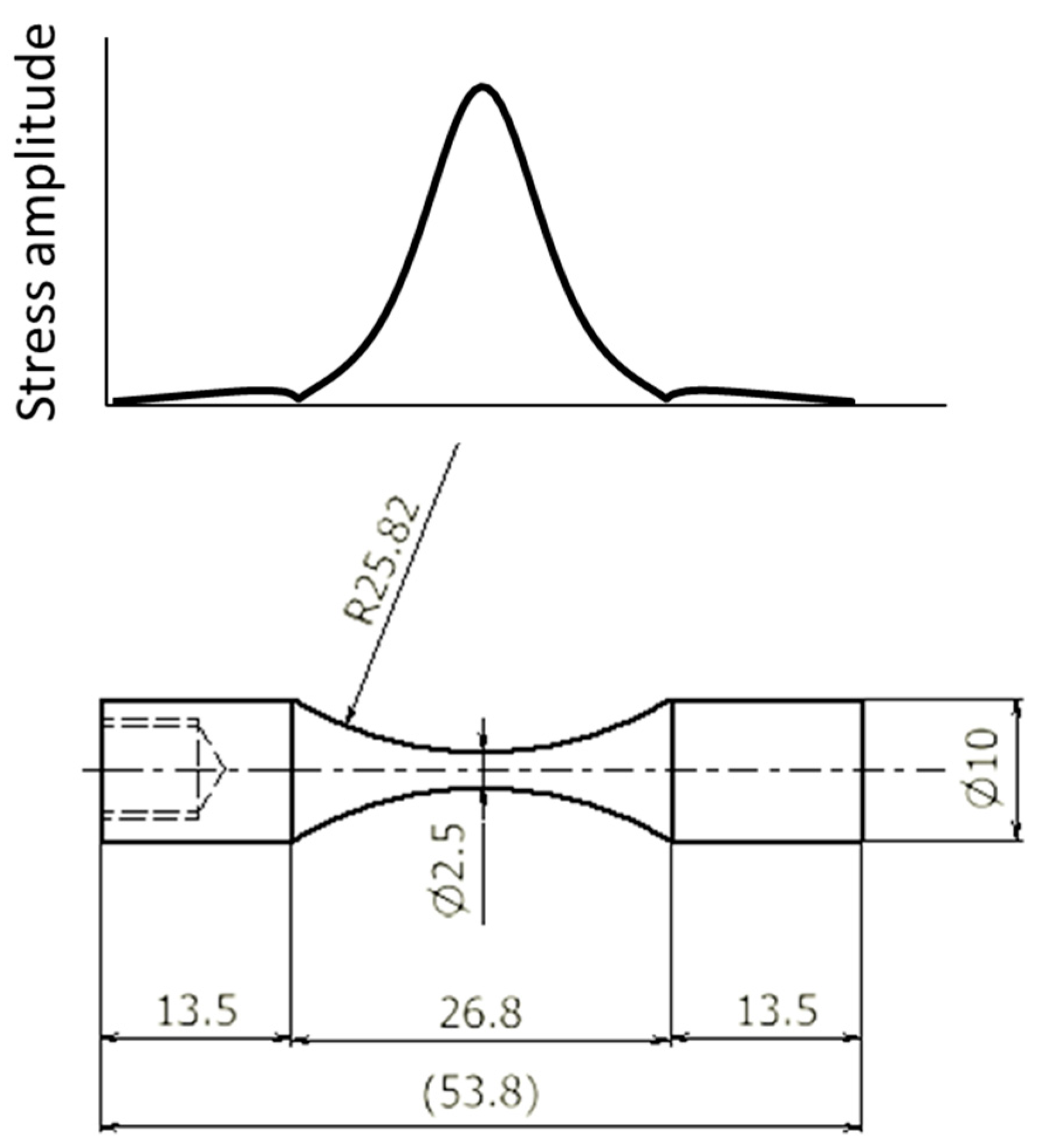
2.2. Ultrasonic Fatigue Testing Machine

An ultrasonic axial fatigue testing machine is mainly composed of a piezoelectric oscillator, an amplifying horn, a specimen, and a controller, as shown in Figure 1 [8]. Sinusoidal electrical input from the signal generator vibrates the piezoelectric oscillator at about 20 kHz. The amplitude of the vibration is, however, only a few μm and not enough to bring fatigue failure to a specimen. Thus, the cyclic vibration of the piezoelectric oscillator is amplified using an amplifying horn. The specimen had the first natural frequency at about 20 kHz of axial vibration mode and was resonated by the external input from the amplifying horn. In this study, an hourglass type specimen was designed by using theoretical formulas [11], and then the specimen shape was tuned by using finite element analysis to obtain exact resonance. The specimen shape and the profiles of axial stress amplitude are presented in Figure 2. In this shape, the maximum axial stress amplitude was achieved at the center of the necked region of the specimen, whose diameter was 2.5 mm. The stress concentration factor Kt at the root of the necked portion was 1.03. The stress ratio R was −1. Fatigue tests were conducted in air with forced cooling using compressed air. Intermittent loading was used to keep the specimen temperature below 100 °C. A loading time of 0.3 s and a dwelling time of 0.4 s were set for the intermittent testing.
The stress amplitude was estimated as follows. First, the relation between the axial displacement amplitude at the end of a specimen and the stress amplitude at the center in the necked region was calculated using finite element analysis. During fatigue testing, the axial displacement at the end of a specimen was monitored using a gap sensor, and the stress amplitude was estimated by substituting the measured axial displacement amplitude into the analytical relation.
To detect fatigue crack initiation, the resonance frequency was monitored during fatigue testing. If the resonance frequency decreased by 50 Hz, fatigue testing was interrupted.
Preliminary fatigue tests were conducted in order to decide the fatigue strength in the very high cycle region of the prepared specimens, and we decided to conduct fatigue testing at σ a = 650 MPa for synchrotron radiation μCT imaging because it is anticipated that a specimen will fail in the range between 107 to 108 cycles by internal fracture from inclusion.

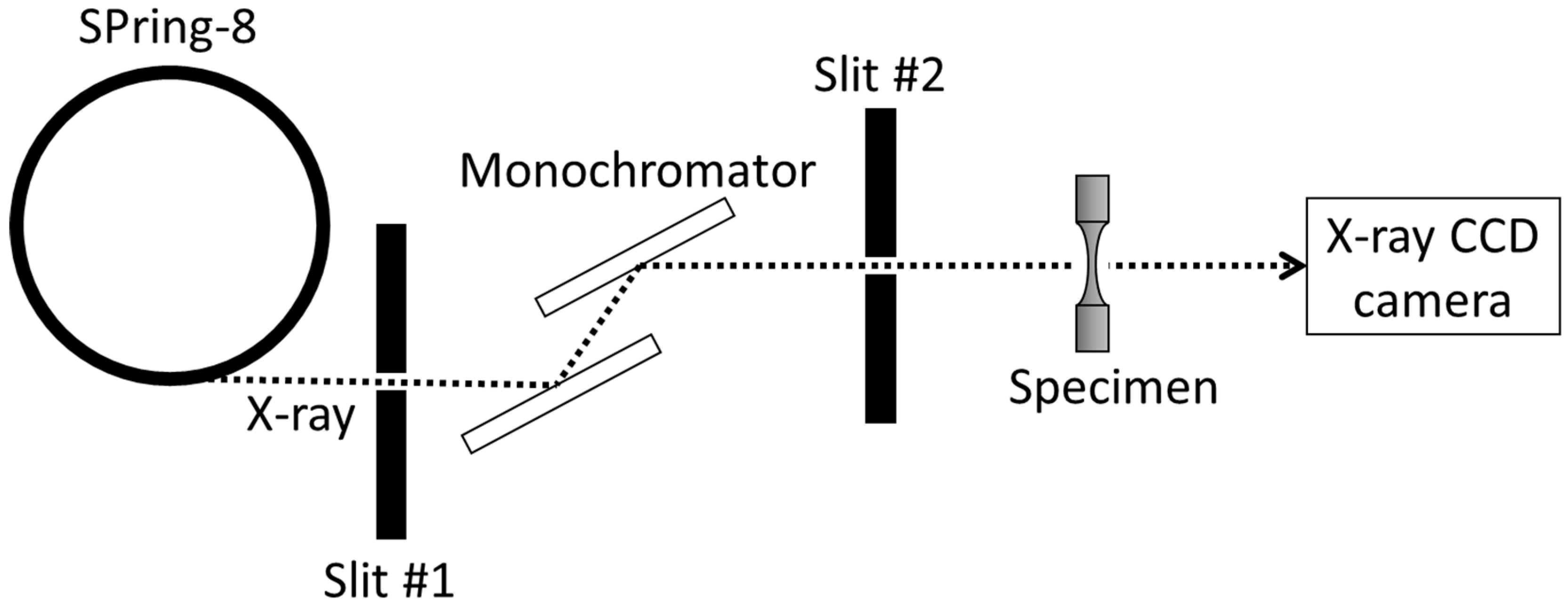
2.3. Synchrotron Radiation μCT Imaging

Synchrotron radiation μCT imaging was conducted at the beamline BL22XU at SPring-8. The maximum X-ray energy was about 70 keV. A specimen was placed on a rotating table so that the specimen axis was arranged on the rotating axis. The set-up of synchrotron radiation μCT imaging is shown in Figure 3. Radiographs were taken at intervals of 0.2 degrees from 0 degrees to 180 degrees; the total number of radiographs was about 900 images. The area of radiographs was equal to the area of incident X-ray, which was H2.1 mm × W4.0 mm, where the width was wider than the diameter of the necked portion of the specimen, i.e., 2.5 mm. The pixel size was 6.5 μm. The stress amplitude at the top and bottom edge of the imaging volume was 95% of the maximum applied stress amplitude of the measured area. During μCT imaging, a specimen was subjected to a static tensile load of 500 MPa, which was lower than the fatigue strength at 109 cycles, by using an in-house tensile loading apparatus in order to open if an internal crack(s) exists. The in-house tensile loading apparatus was mainly composed of an acrylic tube and a coil spring; a specimen was placed in the acrylic tube, fixed at the one end of the acrylic tube, and loaded with the coil spring by tightening a screw located in the other end. A preliminary μCT imaging using a specimen with a fatigue crack from the surface was conducted to assess the feasibility of crack detection. The radiograph of the crack tip implied that it seemed to be possible to identify an internal fatigue crack if the size is on the order of 10 μm.
The first μCT imaging was conducted for a specimen before fatigue testing (N = 0). Then, several sets of fatigue loading were repeated by using an ultrasonic fatigue testing machine and μCT imaging. The cumulative numbers of cycles at μCT imaging were 0, 107, 2 × 10⁷, and 108. Owing to the time limitation for μCT imaging at SPring-8, the repeated μCT imaging was conducted for only one specimen.
For reconstruction of radiographs, software provided by SPring-8 [12] was used.

2.4. Determination of Fatigue Life of the Specimen Used for the Repeated μCT Imaging

After the μCT imaging experiment at SPring-8, the specimen was subjected to fatigue loading until fatigue failure in our laboratory by using the same fatigue testing machine and conditions mentioned above. The specimen failed when the cumulative number of cycles reached 1.4 × 10⁸ cycles from an internal inclusion as shown in Figure 4. The result means that repeated μCT imaging was conducted at 0%, 7.1%, 14.2%, and 70.9% of the fatigue life in the experiments. The chemical composition of the origin was characterized by using EPMA (JXA-8530F, JEOL, Tokyo, Japan) and was identified as an inclusion of Al and Ca oxide with a 30 μm diameter. It should be noted that the cracked position was 3.1 mm far from the center of the imaging volume, which was, unfortunately, out of the imaging volume.

3. Results

An example of a radiograph is shown in Figure 5, and an example of the reconstructed image of a cross section is shown in Figure 6. In the reconstructed image, a block of black pixels is observed. The block of black pixels was considered to be an inclusion [9]. At least 47 inclusions were identified within the imaging volume. Figure 7 shows the locations of the inclusions identified from the reconstructed images before fatigue loading. The projected positions in the vertical and horizontal sections are shown in the left and right figure, respectively. Most of the block size varied from 2 to 6 pixels, which corresponds to 12 μm to 36 μm in diameter. Since an inclusion size as a fatigue origin is, in general, 10 μm or more, the μCT imaging technique used can identify inclusions that may be fatigue origins. In other words, 47 potential fatigue crack origins were non-destructively monitored using the μCT imaging technique in the experiment, even though the repeated μCT imaging was conducted for only one specimen due to time limitation.
Then, reconstructed images before and after fatigue loading were compared for investigating crack formation from inclusions. An example of reconstructed images of an inclusion subjected to almost the maximum stress amplitude, which is labeled “21” and thick circled in Figure 7, is shown in Figure 8. If a fatigue crack exits around an inclusion, crack opening occurs due to the applied load exerted by the in-house tensile loading apparatus during μCT imaging. Thus, the contrast of a reconstructed image around the inclusion may change if there is a fatigue crack around the inclusion. However, for every identified inclusion, no identifiable contrast change was observed before and after fatigue loading.
Similarly, crack nucleation in the base material, so-called matrix cracking, was carefully inspected, but no identifiable crack nucleation was observed in the base material.

4. Discussion

As mentioned in Introduction, it is thought that most of the fatigue life is consumed by the formation of ODA and the crack growth rate in ODA is very slow, whereas penny-shaped microcracks around many inclusions nucleate in the early stage of very high cycle fatigue [4,5,6]. Although the internal fatigue origin was not included in the observation volume, no identifiable internal fatigue crack around every inclusion was observed and there was at least up to 70.9% of fatigue life in the imaging volume.
In this study, we could not inspect the formation of ODA from the reconstructed images after fatigue loading. There might be several possible reasons to interpret the results. The first possible reason is that there is fatigue damage around inclusions, but the size is so small that the fatigue damage cannot be detected by this set-up. The second possible reason is that fatigue damage occurs just before the final break, and so there is no damage around inclusions in the μCT images. The resolution of the reconstructed images was limited to 6.5 μm, and the incident angle of X-ray was needed to be set almost parallel to the crack plane of ODA. For more detailed in-situ-inspection of ODA formation, improvements of resolution and experimental set-up should be required.
The fatigue crack nucleated from an inclusion in this study. Thus, the fatigue strength is compared with the prediction of Murakami’s approach [10], which is widely used for predicting fatigue strength for alloy steels. The diameter of the inclusion of the fatigue origin was about 20 μm, and the Vickers hardness was 435 HV. Substituting the values into the following equation for internal inclusion gives an estimate of the fatigue strength for the specimen.
σ w = 1.56 ( H V + 120 ) ( a r e a ) 1 / 6
The predicted fatigue strength is 540 MPa, which is 110 MPa lower than the applied stress amplitude in this experiment. It is known that a higher strain rate by ultrasonic fatigue testing may results in higher fatigue strength [13]. The higher fatigue strength in this experiment was possibly caused by a higher strain rate.

5. Conclusions

In this study, synchrotron radiation μCT imaging of Cr-Mo steel subjected to cyclic loading in excess of 108 cycles was conducted in order to examine the feasibility of applying synchrotron radiation μCT imaging to alloy steels for the non-destructive inspection of inclusions for potential origins of internal fatigue damage in the very high cycle region.
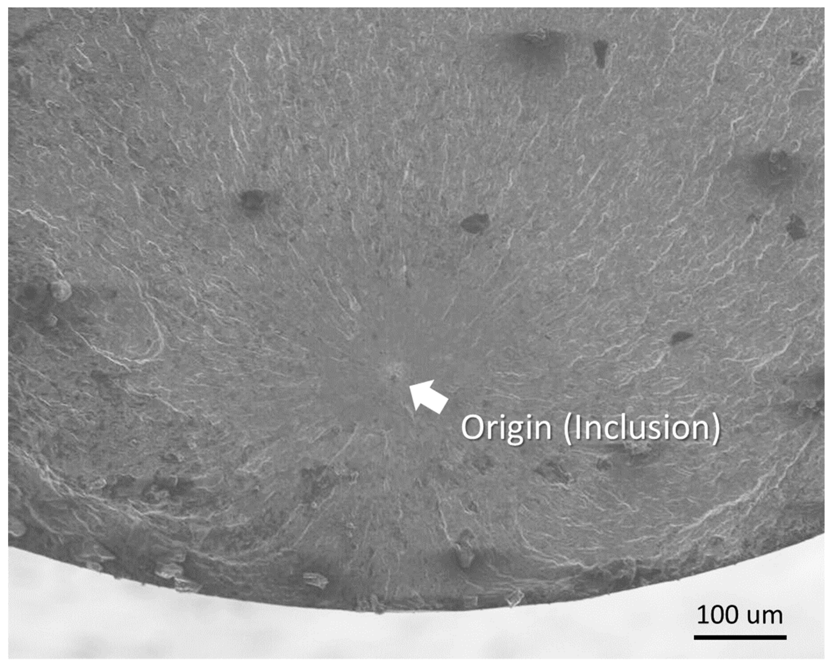
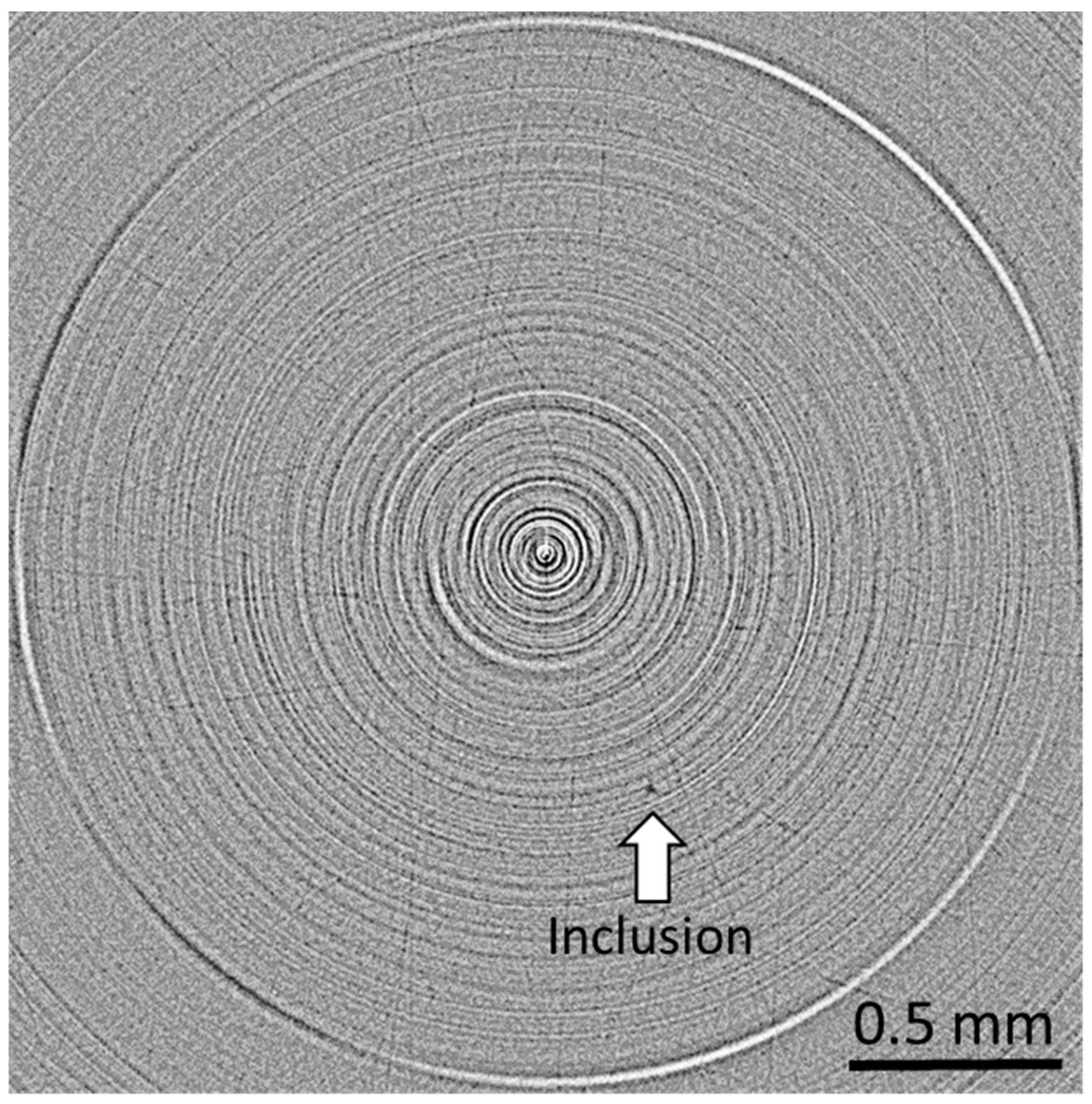
  • The proposed experimental set-up allows us to observe inclusions of more than 10 μm nondestructively, one of which is the potential origin of an internal fatigue crack.
  • No identifiable internal damage was observed within the imaging volume at least up to 70% of the fatigue life. For more detailed in-situ-inspection of ODA formation, improvements of resolution and experimental set-up should be required.

Author Contributions

Conceptualization, Y.S., T.F. and K.A.; methodology, Y.S., K.A., T.S. and A.S.; formal analysis, S.M.; investigation, Y.S., S.M., T.F. and K.A.; writing—original draft preparation, Y.S. and S.M.; writing—review and editing, T.F. and K.T.; visualization, S.M.; supervision, Y.S. and K.T.; project administration, K.A.; funding acquisition, K.A. and T.S.

Funding

The synchrotron radiation experiments were performed at the BL22XU of SPring-8 with the approval of the Japan Synchrotron Radiation Research Institute (JASRI) (Proposal No. 2014B3723, 2015A3723, and 2016B3722).

Acknowledgments

We thank Masato Nishikawa for his great effort in preliminary experiments in SPring-8, and Yuki Shimizu, Masato Fujiwara, Ryota Nagayama, and Suzuyo Takahata for their help in the experiment in SPring-8, all of whom were students at Shizuoka University. We also thank Yoshihito Kuroshima at Kyushu Institute of Technology for his valuable suggestions and discussion.

Conflicts of Interest

The authors declare no conflict of interest.

References

  1. Sakai, T. Review and prospects for current studies on very high cycle fatigue of metallic materials for machine structural use. J. Solid Mech. Mater. Eng. 2009, 3, 425–439. [Google Scholar] [CrossRef]
  2. Murakami, Y.; Nomoto, T.; Ueda, T.; Murakami, Y. On the Mechanism of Fatigue Failure in the Superlong Life Regime (N > 107 cycles). Part I: Influence of Hydrogen Trapped by Inclusions. Fatigue Fract. Eng. Mater. Struct. 2000, 23, 893–902. [Google Scholar] [CrossRef]
  3. Sakai, T.; Sato, Y.; Oguma, N. Characteristic S–N property of high carbon chromium bearing steel under axial loading in long life fatigue. Trans. Jpn. Soc. Mech. Eng. A 2001, 67, 1980–1987. [Google Scholar] [CrossRef]
  4. Kuroshima, Y.; Ikeda, T.; Harada, M.; Harada, S. Subsurface crack growth behavior on high cycle fatigue of high strength steel. Trans. Jpn. Soc. Mech. Eng. A 1998, 64, 2536–2541. [Google Scholar] [CrossRef]
  5. Luo, L.; Shiozawa, K. Effect of two-step load variation on super-long life fatigue and internal crack growth behavior of high carbon-chromium bearing steel. Trans. Jpn. Soc. Mech. Eng. A 2002, 68, 1666–1673. [Google Scholar] [CrossRef]
  6. Ogawa, T.; Stanzal-Tschegg, S.E.; Shönbaue, B.M. A fracture mechanics approach to interior fatigue crack growth in the very high cycle regime. Eng. Fract. Mech. 2014, 115, 241–254. [Google Scholar] [CrossRef]
  7. Yoshinaka, F.; Nakamura, T.; Nakayama, S.; Shiozawa, D.; Nakai, Y.; Uesugi, K. Non-destructive observation of internal fatigue crack growth in Ti-6Al-4V by using synchrotron radiation μCT imaging. Int. J. Fatigue 2016, 93, 397–405. [Google Scholar] [CrossRef]
  8. Kasahara, R.; Nishikawa, M.; Shimamura, Y.; Tohgo, K.; Fujii, T. Evaluation of very high cycle fatigue properties of β-titanium alloy by using an ultrasonic fatigue testing machine. Key Eng. Mater. 2016, 725, 366–371. [Google Scholar] [CrossRef]
  9. Nakai, Y.; Shiozawa, D.; Morinaga, Y.; Kurimura, T.; Okada, H.; Miyashita, T. Observation of inclusions and defects in steels by micro computed-tomography using ultrabright synchrotron radiation. In Proceedings of the Fourth International Conference on Very High Cycle Fatigue, Ann Arbor, MI, USA, 19–22 August 2007; Allison, J.E., Jones, J.W., Larsen, J.M., Ritche, R.O., Eds.; TMS: Warrendale, PA, USA, 2007; pp. 67–72. [Google Scholar]
  10. Murakami, R. Metal Fatigue: Effects of Small Defects and Nonmetallic Inclusion; Yukendo Ltd.: Tokyo, Japan, 1993; p. 90. ISBN 978-4842593029. [Google Scholar]
  11. WES 1112: Standard Method for the Ultrasonic Fatigue Test in Metallic Materials; The Japan Welding Engineering Society: Tokyo, Japan, 2017; p. 7.
  12. Computed Tomography in SPring-8 (SP-μCT). Available online: http://www-bl20.spring8.or.jp/xct/index-e.html (accessed on 15 March 2019).
  13. Mayer, H. Recent Developments in Ultrasonic Fatigue. Fatigue Fract. Eng. Mater. Struct. 2016, 39, 3–29. [Google Scholar] [CrossRef]
Figure 1. Configuration of an ultrasonic fatigue testing machine.
Metals 09 00527 g001
Figure 2. Specimen shape and the profile of the axial stress amplitude, along with the specimen axis.
Metals 09 00527 g002
Figure 3. Set-up of the synchrotron radiation μCT imaging.
Metals 09 00527 g003
Figure 4. Fatigue origin of the specimen used for the repeated synchrotron radiation μCT imaging.
Metals 09 00527 g004
Figure 5. Example of a radiograph.
Metals 09 00527 g005
Figure 6. Example of the reconstructed image of a cross section.
Metals 09 00527 g006
Figure 7. Locations of inclusions.
Metals 09 00527 g007
Figure 8. Reconstructed images of an inclusion #21 at every observation step.
Metals 09 00527 g008
Table 1. Chemical composition of SCM420H (wt%).
CSiMnPSCuCrNiMoFe
0.20.180.80.020.020.011.120.010.19Bal.

