Article

The Role of Acoustic Pressure during Solidification of AlSi7Mg Alloy in Sand Mold Casting

1
CMEMS—UMinho, Campus de Azurém, 4800-058 Guimarães, Portugal
2
MEtriCS—UMinho, Campus de Azurém, 4800-058 Guimarães, Portugal
*
Author to whom correspondence should be addressed.
Metals 2019, 9(5), 490; https://doi.org/10.3390/met9050490
Submission received: 25 March 2019 / Revised: 23 April 2019 / Accepted: 25 April 2019 / Published: 27 April 2019
(This article belongs to the Special Issue Casting and Forming of Advanced Aluminum Alloys)

Abstract

:
New alloy processes have been developed and casting techniques are continuously evolving. Such constant development implies a consequent development and optimization of melt processing and treatment. The present work proposes a method for studying the influence of acoustic pressure in the overall refinement of sand cast aluminum alloys, using and correlating experimental and numerical approaches. It is shown that the refinement/modification of the α-Al matrix is a consequence of the acoustic activation caused in the liquid metal directly below the face of the acoustic radiator. Near the feeder, there is a clear homogeneity in the morphology of the α-Al with respect to grain size and grain circularity. However, the damping of acoustic pressure as the melt is moved away from the feeder increases and the influence of ultrasound is reduced, even though the higher cooling rate seems to compensate for this effect.

1. Introduction

Aluminum alloys are thriving in the automotive, aeronautics and aerospace industries, displacing applications that have traditionally been occupied by other alloys [1]. The performance of a mechanical component is often conditioned and limited by the characteristics of the materials themselves, as well as by limitations of the manufacturing processes and, more specifically, by their microstructure. Although, their use is widespread, the casting of aluminum alloys is not an easy process, since they are prone to nucleate and grow coarse and dendritic microstructures [2,3]. Additionally, aluminum alloys are characterized by a high absorption of hydrogen during melting and casting [4,5]. Thus, the increasing use of aluminum components with superior mechanical and fatigue properties requires suitable and high-efficiency casting processes [6]. This includes the melt treatment [7] to develop suitable microstructures, eliminate inclusions, and reduce porosities and shrinkage defects, which are the main cause of failure in aluminum components [8].
In the industrial practice of aluminum casting, three melt treatment operations are usually carried out in addition to the removal of slag, all of them chemically-based and presenting significant environmental impacts: (i) degassing, by reducing the hydrogen content of the melt, which is achieved by gas purging using mainly inert gases [9,10]; (ii) microstructure refinement, by the addition of Al-Ti-B type master alloys in proportions adjusted to the specific aluminum alloy [11,12,13]; (iii) eutectic silicon modification, usually carried out by the addition of master alloys containing Sr [12,14]. Although these three stages (degassing, grain refinement, modification of eutectic silicon), are vital to improving the mechanical performance of castings, the need to find more efficient, viable and clean treatment alternatives has fostered the search for new melt treatment techniques and technologies.
In the last decade, we have witnessed the development of highly efficient aluminum melt treatment techniques based on the use of acoustic energy [15,16,17,18,19]. The influence of ultrasound on the refinement/modification of the microstructure is based on physical phenomena due to the high acoustic intensity propagated through the liquid metal [17]. Two mechanisms have been proposed to explain the refinement of microstructures by ultrasound, dendritic fragmentation and cavitation induced heterogeneous nucleation [20,21]. However, the mechanism of heterogeneous nucleation induced by cavitation seems to be the most valid hypothesis, being supported by the majority of researchers who have worked in this field [22]. However, in order for this technique to be efficient, it is imperative that the ultrasonic system is correctly designed according to the specific needs of the casting process. This enhances the overall success of the technique and optimizes the casting component integrity.
For that purpose, the present work aimed to study the interaction between the requirements imposed by the melt conditions (i.e., the melt temperature/volume) and the constraints imposed by the manufacturing process (geometry of casting) in the optimization of an ultrasonic system and its impact on the overall microstructures [23]. Furthermore, considering their physical processing, a numerical model was used to investigate the associated acoustic pressure fields developed in the transmission medium and their role in the grain refinement.

2. Methodology

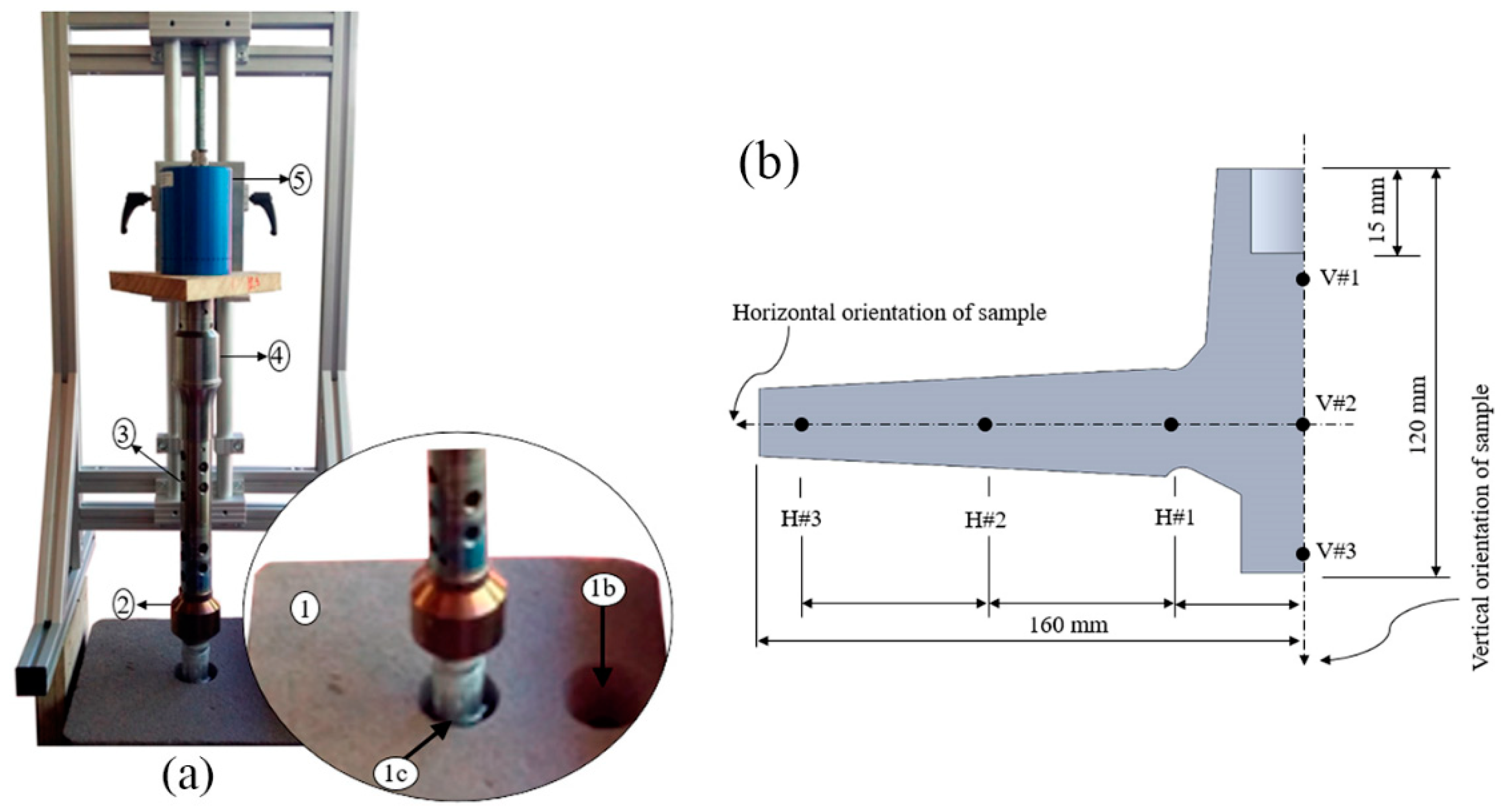
2.1. Experimental Setup and Procedure

The excellent castability and ductility, combined with a reduced tendency to defect formation, have been crucial factors in increasing the application of AlSi7Mg based alloys in the production of structural castings cast by sand molding [24,25]. The mechanical properties of such castings can be improved by solubilizing and aging treatments, providing uniform distribution of Mg and Si precipitates in the aluminum matrix [26,27].
The melt charges used in this work were prepared from an AlSi7Mg0.3 alloy, with the composition presented in Table 1.
Melting charges weighing 10 kg were previously cut from a primary melt commercial ingot and later washed and dried to eliminate the cutting lubricant. After melting and overheating at the pre-established testing temperature (720 ± 5 °C), the melt was kept isothermal for a 30 min period for better homogenization. After this period, the melt was degassed for 5 min using ultrasound technology. The 5-minute period and the operational parameters were chosen according to works previously published by the authors [28]. After degassing, the melt was allowed to cool and was poured at 700 ± 5 °C into a sand mold, as shown in Figure 1. Immediately after pouring, the pre-heated acoustic radiator was positioned over the feeder with an immersion depth of 15 mm in the melt, to ensure the maximum transfer of acoustic energy to the melt from the thick zone (feeder) to the thin areas of the casting. Acoustic energy was supplied until the metal reached the solidus temperature +10 °C.
Samples for microstructure characterization were taken from every cast sample by sectioning them perpendicularly to their vertical and horizontal axis (respectively, V#1 to V#3 and H#1 to H#3), according to Figure 1b. They were ground using 1200 μm SiC and polished down to 1 μm. An optical microscope (OM) (LEICA DM 2500M) and the ImageJ v1.46 computer application were used to determine the average grain size, d, and circularity, Rn, using Equations (1) and (2) where A corresponds to the area and P to the perimeter of the α-grains.
d = 2 × A π
R n = 4 × π × A P 2

2.2. Computational Modeling

In order to study the acoustic propagation in liquid metal, a simulation model was developed using the COMSOL v5.2a Multiphysics module—Acoustic Piezoeloectric Interaction, Frequency Domain, according to Figure 2. Considering that the acoustic wave propagation is linear, and the shear stresses are negligible for fluids, the acoustic pressure can be calculated by applying the following wave equation [6,7]:
( 1 ρ P ) 1 ρ c 2 2 P t 2 = 0
where ρ is the density of the liquid metal, c is the sound velocity in the liquid metal and t is time. For the case of a harmonic wave in time, the pressure varies according to:
P ( r , t ) = p ( r ) i ω t
where, ω = 2πf is the angular frequency and p is the acoustic pressure. Assuming that the same harmonic is time dependent, in the same terms, Equation (3) can be reduced, through Equation (4), to the Helmholtz equation:
( 1 ρ p ) ω 2 ρ c 2 p = 0
The Acoustic Piezoeloectric Interaction module in COMSOL Multiphysics was used to perform an analysis in the frequency domain. This combines the effects of (i) sound pressure and (ii) piezoelectric, linking the variations of acoustic pressure with the solids that are actuated by the piezoelectric effect of PZT. The physical interface also includes electrostatic elements to solve the electric field in the piezoelectric material. The Helmholtz equation is solved in the fluid domain and the structural equations in the solid domain, together with the constructive relations necessary for the piezoelectric modeling. The physical interface that solves the Helmholtz equation is suitable for the present study, in the domain of linear frequencies with harmonic variation of the pressure field.
In order to evaluate the profile of the acoustic pressure during the deformation of the solids actuated by the PZT piezoelectric effect, water was used since this is a suitable liquid medium to simulate the refinement / modification mechanism that occurs in melts of aluminum alloys at 660–700 °C [29]. With the appropriate boundary conditions, the Helmholtz equation can be solved through a range of numerical methods [6,8]. The accuracy of the numerical solution of the Helmholtz equation depends significantly on the wave number k(k = ω/c). The main boundary conditions are described as, (i) p = 0 (condition of total waves reflection, attributed to the liquid-air interfaces); (ii) p = p0 (interface of the acoustic radiator with the liquid metal); (iii) δp/δn = 0 (condition of “rigid walls” attributed to the lateral walls of the acoustic radiator); (iv) (1/ρ)(δp/δn) + iωp/Z = 0 (acoustic impedance limit condition Z attributed to the container walls).

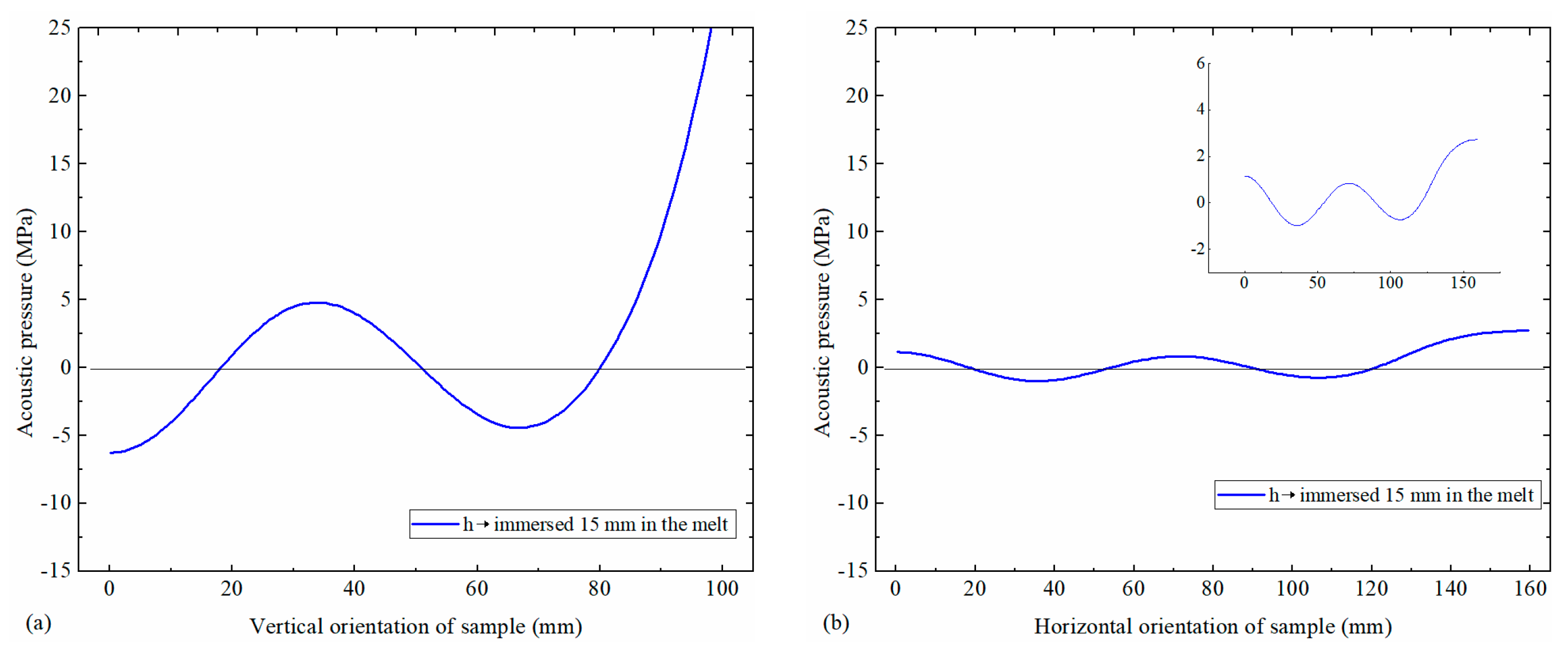
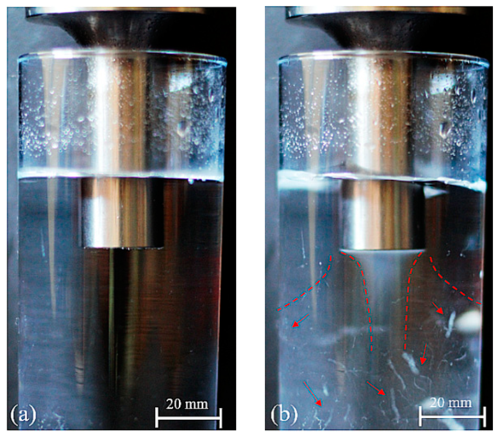
3. Results and Discussion

Aluminum alloys are known for their high affinity to hydrogen at high temperature, promoting the appearance of numerous inclusions in the microstructure after solidification, with porosity being the most relevant and harmful defect compromising the strength of the component [4,30,31]. To assess the similarity of the porosity levels in samples, the melts were degassed before pouring at the desired temperature (700 ± 5 °C [31]), using the Multi-Mode Frequency, Modulated (MMM) ultrasonic technology, to ensure that the density of the bath was identical for every experiment. The average density reached in the experiments was 2.68 ± 0.1 (0.5% ± 0.07 porosity).
Figure 3 shows the variation of the α-Al grain size and circularity of AlSi7Mg0.3 alloy processed by ultrasound, with an average frequency of 19.9 ± 0.2 kHz and 40% of the system power (400 W—corresponding to approximately 60 μm), evaluated in a longitudinal section of the feeder (V#1 to V#3 samples, according to Figure 1). The respective microstructures are shown in Figure 4a–c.
The experimental results suggest that the feeder (central zone of the feeder and directly below the acoustic radiator) presents a microstructure with a well-defined globular morphology. Overall, the variation of grain size and circularity apparent was minimal, as can confirmed by the standard deviations presented in Figure 3. Indeed, the average grain size and circularity for all characterized positions were, respectively, 120 μm and 0.8. As demonstrated by Puga et al. [32] and Eskin et al. [29] the zone below the flat acoustic radiator is able to promote extremely intense cavitation, being able to promote nucleation and further to this, an increase in the quantity of α-Al grains, and consequently, the reduction of their diameter and a globular morphology.
Figure 5 shows the variation of the α-Al grain size and circularity of AlSi7Mg0.3 alloy processed by ultrasound, at the average frequency of 19.9 ± 0.2 kHz (resonance frequency at high temperature), with the distance to the acoustic radiator in the feeder (H#1 to H#3 samples, according to Figure 1). The respective microstructures are shown in Figure 6a–c.
The results presented suggest that with increasing distance to the acoustic radiator the α-Al grain size tends to increase, and the grain circularity tends to decrease. Although the grain size tends to increase, the matrix continues to present a quasi-globular morphology with some indications of rosette grains. This is an opposite tendency compared to what happens with the traditional processes of sand casting, where the matrix tends to present a dendritic morphology, even after chemical melt treatments.
Furthermore, the results presented in Figure 5 and Figure 6 suggest that the cooling rate influences the grain morphology. Although the effect of ultrasound promotes a globular matrix, the fast cooling rates in thinner sections (e.g., position H#3 with a section solidification module 0.41) tends to overlap the effect of ultrasound. However, this effect also allows the formation of a thinner but non-dendritic microstructure, which is beneficial for the mechanical properties. However, in sections directly affected by the acoustic radiator (e.g., feeder—Figure 3 and Figure 4), it is suggested that the morphology of the Al matrix (grain size and circularity) may be directly affected by the cavitation mechanism.
Contrary to the traditional process of refinement, where the addition of the master alloy Al-Ti-B is generally used, in the present approach this issue is not considered. Overall, the applied acoustic intensity is sufficient for: (i) converting the displacement of piezoelectric into kinetic energy in the liquid; (ii) creating acoustic cavitation and acoustic streams able to promote the nucleation and homogenization in the melt; (iii) increasing the temperature of the medium due to bubble collapse, which can promote and accelerate the α-Al grains.
A numerical simulation study was performed to validate the aforementioned hypothesis and experimental results. Figure 7 presents the numerical results of the axial displacement (evaluated in solid parts and the acoustic pressure in the melt), for the whole system, when the acoustic radiator was immersed in water at a depth of 15 mm, according to the boundary conditions represented in Figure 2.
According to the eigenfrequency results of the acoustic radiator, the first longitudinal compression mode was located at 20.23 kHz. This matches well with the operation frequency of the transducer, as can be proved by the experimental electrical impedance results measured by the authors. Thus, in order to numerically quantify the acoustic pressure in the medium, a domain frequency study was performed at f0 = 20.20 kHz. Figure 8a,b presents the numerical values of acoustic pressure along the horizontal section with the distance to the acoustic radiator in the feeder (H#1 to H#2) and the vertical component beneath the feeder (V#1 to V#3).
As can be observed in Figure 8a, a sinusoidal curve with a positive and negative acoustic pressure of at least 5 MPa in the vertical component is reached in the melt. According to Eskin’s work [29] the threshold of acoustic pressure to verify cavitation is around 2 MPa. Indeed, according to experimental results for parameters numerically evaluated, the level of cavitation and acoustic streams at 40% system power (using the same acoustic radiator that numerically simulated) is totally defined, as can be observed in Figure 9. It may be clearly observed that in corresponding conditions (i.e., similar fluid and boundary conditions) that are initially resting (Figure 9a), it is possible to promote streaming and cavitation effects by the use of the detailed ultrasonic system.
Contrary to high values of acoustic pressure measured along the longitudinal section of the feeder (V#1 to V#3), in the horizontal cylindrical section (H#1 to H#2) the maximum acoustic pressure registered was 1 MPa (Figure 8b). Considering the high level of cavitation and acoustic streams created below the flat surface of the acoustic radiator, as well as the long interval time of solidification, it is suggested that a mixing and distribution of nuclei can travel along the cylindrical shape and contribute to the refining of Al grain reported in results of Figure 5 and Figure 6. Furthermore, according to Figure 10, there is a correlation between the acoustic pressure and the grain size. It is shown that as the pressure increases, the grain size tends to decrease by an exponential decay function.
It is suggested that there is a threshold for the acoustic pressure grain refinement effect. In these particular conditions, it is apparent that for acoustic pressures higher than 2 MPa there are no significant benefits in terms of grain refinement.

4. Conclusions

This study explored the influence of acoustic pressure in the overall refinement of sand cast aluminum alloys, using experimental and numerical approaches to detail the overall pressure distribution and distance to acoustic excitation. According to the results, the following conclusions may be drawn:
(1) The mechanism of refinement/modification of the α-Al matrix is a consequence of the acoustic activation caused in the liquid metal directly below the face of the acoustic radiator and is able to be distributed by different mold cavity area branches.
(2) In areas near the feeder there is a clear homogeneity in the morphology of the α-Al with respect to grain size and grain circularity. That is, the influence of the acoustic radiator in the liquid medium immediately below its top flat face is evident.
(3) In areas that are more distant to the feeder, the acoustic pressure directly caused by the acoustic radiator tends not to induce significant alteration in the grain size due to the lower pressure; however, this is compensated for by the higher cooling rates.
(4) Knowledge of the acoustic pressure profile, together with the analysis of the positioning of the acoustic radiator for refinement/modification the α-Al matrix validated through the use of numerical models, will allow high integrity castings to be obtained, with a tendency towards increased mechanical properties when compared to traditional treatment methods.

Author Contributions

Conceptualization, V.H.C. and H.P.; Methodology, V.H.P. and H.P.; Validation, H.P. and J.B.; Formal analysis, V.H.C. and H.P.; Resources, H.P.; Data curation, V.H.P. and J.B.; Writing—original draft preparation, V.H.P. and H.P.

Funding

This research received no external funding.

Acknowledgments

This work was supported by FCT funding through the project PTDC/EMEEME/30967/2017 (NORTE-0145-FEDER-030967) and by FEDER funding through COMPETE 2020, NORTE2020, PORTUGAL2020 – Programa Operacional Competitividade e Internacionalização (POCI). Additionally, this work was supported by FCT with the reference project UID/EEA/04436/2019.

Conflicts of Interest

The authors declare no conflicts of interest.

References

  1. Nguyen, R.T.; Imholte, D.D.; Rios, O.R.; Weiss, D.; Sims, Z.; Stromme, E.; McCall, S.K. Anticipating impacts of introducing aluminum-cerium alloys into the United States automotive market. Resour. Conserv. Recycl. 2019, 144, 340–349. [Google Scholar] [CrossRef]
  2. Jarry, P.; Rappaz, M. Recent advances in the metallurgy of aluminium alloys. Part I: Solidification and casting. C. R. Phys. 2018, 19, 672–687. [Google Scholar] [CrossRef]
  3. Liang, G.; Ali, Y.; You, G.; Zhang, M.-X. Effect of cooling rate on grain refinement of cast aluminium alloys. Materialia 2018, 3, 113–121. [Google Scholar] [CrossRef]
  4. Zhang, Q.; Wang, T.; Yao, Z.; Zhu, M. Modeling of hydrogen porosity formation during solidification of dendrites and irregular eutectics in Al–Si alloys. Materialia 2018, 4, 211–220. [Google Scholar] [CrossRef]
  5. Brůna, M.; Bolibruchová, D.; Pastirčák, R. Numerical Simulation of Porosity for Al Based Alloys. Procedia Eng. 2017, 177, 488–495. [Google Scholar] [CrossRef]
  6. Su, H.; Toda, H.; Masunaga, R.; Shimizu, K.; Gao, H.; Sasaki, K.; Bhuiyan, M.S.; Uesugi, K.; Takeuchi, A.; Watanabe, Y. Influence of hydrogen on strain localization and fracture behavior in AlZnMgCu aluminum alloys. Acta Mater. 2018, 159, 332–343. [Google Scholar] [CrossRef]
  7. Jung, J.-G.; Cho, Y.-H.; Lee, J.-M.; Kim, H.-W.; Euh, K. Designing the composition and processing route of aluminum alloys using CALPHAD: Case studies. Calphad 2019, 64, 236–247. [Google Scholar] [CrossRef]
  8. Rotella, A.; Nadot, Y.; Piellard, M.; Augustin, R.; Fleuriot, M. Fatigue limit of a cast Al-Si-Mg alloy (A357-T6) with natural casting shrinkages using ASTM standard X-ray inspection. Int. J. Fatigue 2018, 114, 177–188. [Google Scholar] [CrossRef]
  9. Mancilla, E.; Cruz-Méndez, W.; Garduño, I.E.; González-Rivera, C.; Ramírez-Argáez, M.A.; Ascanio, G. Comparison of the hydrodynamic performance of rotor-injector devices in a water physical model of an aluminum degassing ladle. Chem. Eng. Res. Des. 2017, 118, 158–169. [Google Scholar] [CrossRef]
  10. Haghayeghi, R.; Bahai, H.; Kapranos, P. Effect of ultrasonic argon degassing on dissolved hydrogen in aluminium alloy. Mater. Lett. 2012, 82, 230–232. [Google Scholar] [CrossRef]
  11. Li, J.; Huang, M.; Ma, M.; Ye, W.; Liu, D.; Sone, D.; Bai, B.; Fang, H. Performance comparison of AlTiC and AlTiB master alloys in grain refinement of commercial and high purity aluminum. Trans. Nonferrous Met. Soc. China 2006, 16, 242–253. [Google Scholar] [CrossRef]
  12. Lu, L.; Dahle, A.K. Effects of combined additions of Sr and AlTiB grain refiners in hypoeutectic Al–Si foundry alloys. Mater. Sci. Eng. A 2006, 435–436, 288–296. [Google Scholar] [CrossRef]
  13. Ding, W.; Xu, C.; Hou, X.; Zhao, X.; Chen, T.; Zhao, W.; Xia, T.; Qiao, J. Preparation and synthesis thermokinetics of novel Al-Ti-C-La composite master alloys. J. Alloys Compd. 2019, 776, 904–911. [Google Scholar] [CrossRef]
  14. Öztürk, İ.; Hapçı Ağaoğlu, G.; Erzi, E.; Dispinar, D.; Orhan, G. Effects of strontium addition on the microstructure and corrosion behavior of A356 aluminum alloy. J. Alloys Compd. 2018, 763, 384–391. [Google Scholar] [CrossRef]
  15. Barbosa, J.; Puga, H. Ultrasonic Melt Treatment of Light Alloys. Int. J. Met. 2019, 13, 180–189. [Google Scholar] [CrossRef]
  16. Eskin, D.G.; Tzanakis, I.; Wang, F.; Lebon, G.S.B.; Subroto, T.; Pericleous, K.; Mi, J. Fundamental studies of ultrasonic melt processing. Ultrason. Sonochem. 2019, 52, 455–467. [Google Scholar] [CrossRef] [PubMed]
  17. Tzanakis, I.; Lebon, G.S.B.; Eskin, D.G.; Pericleous, K.A. Characterisation of the ultrasonic acoustic spectrum and pressure field in aluminium melt with an advanced cavitometer. J. Mater. Process. Technol. 2016, 229, 582–586. [Google Scholar] [CrossRef] [Green Version]
  18. Barbosa, J.; Puga, H. Ultrasonic melt processing in the low pressure investment casting of Al alloys. J. Mater. Process. Technol. 2017, 244, 150–156. [Google Scholar] [CrossRef]
  19. Tuan, N.Q.; Puga, H.; Barbosa, J.; Pinto, A.M.P. Grain refinement of Al-Mg-Sc alloy by ultrasonic treatment. Met. Mater. Int. 2015, 21, 72–78. [Google Scholar] [CrossRef] [Green Version]
  20. Kotadia, H.R.; Qian, M.; Das, A. Solidification of aluminium alloys under ultrasonication: An overview. Trans. Indian Inst. Met. 2018, 71, 2681–2686. [Google Scholar] [CrossRef]
  21. Wang, G.; Wang, Q.; Easton, M.A.; Dargusch, M.S.; Qian, M.; Eskin, D.G.; StJohn, D.H. Role of ultrasonic treatment, inoculation and solute in the grain refinement of commercial purity aluminium. Sci. Rep. 2017, 7, 9729. [Google Scholar] [CrossRef] [PubMed] [Green Version]
  22. Puga, H.; Barbosa, J.; Costa, S.; Ribeiro, S.; Pinto, A.M.P.; Prokic, M. Influence of indirect ultrasonic vibration on the microstructure and mechanical behavior of Al–Si–Cu alloy. Mater. Sci. Eng. A 2013, 560, 589–595. [Google Scholar] [CrossRef] [Green Version]
  23. Puga, H.; Carneiro, V.; Barbosa, J.; Vieira, V. Effect of ultrasonic treatment in the static and dynamic mechanical behavior of AZ91D Mg alloy. Metals 2015, 5, 2210–2221. [Google Scholar] [CrossRef]
  24. Weiss, D. Chapter 5—Advances in the Sand Casting of Aluminium Alloys. In Fundamentals of Aluminium Metallurgy; Lumley, R.N., Ed.; Woodhead Publishing: Sawston, UK, 2018; pp. 159–171. ISBN 978-0-08-102063-0. [Google Scholar]
  25. Shangguan, H.; Kang, J.; Deng, C.; Hu, Y.; Huang, T. 3D-printed shell-truss sand mold for aluminum castings. J. Mater. Process. Technol. 2017, 250, 247–253. [Google Scholar] [CrossRef]
  26. Carneiro, V.H.; Puga, H. Solution treatment enhances both static and damping properties of Al–Si–Mg alloys. Metall. Mater. Trans. A 2018, 49, 5942–5945. [Google Scholar] [CrossRef]
  27. Carneiro, V.H.; Puga, H.; Meireles, J. Heat treatment as a route to tailor the yield-damping properties in A356 alloys. Mater. Sci. Eng. A 2018, 729, 1–8. [Google Scholar] [CrossRef]
  28. Puga, H.; Barbosa, J.; Seabra, E.; Ribeiro, S.; Prokic, M. The influence of processing parameters on the ultrasonic degassing of molten AlSi9Cu3 aluminium alloy. Mater. Lett. 2009, 63, 806–808. [Google Scholar] [CrossRef]
  29. Eskin, G.I. Ultrasonic Treatment of Light Alloy Melts; CRC Press: Boca Raton, FL, USA, 1998; ISBN 1-4987-0179-5. [Google Scholar]
  30. Mozammil, S.; Karloopia, J.; Jha, P.K. Investigation of porosity in Al casting. Mater. Today Proc. 2018, 5, 17270–17276. [Google Scholar] [CrossRef]
  31. Dispinar, D.; Akhtar, S.; Nordmark, A.; Di Sabatino, M.; Arnberg, L. Degassing, hydrogen and porosity phenomena in A356. Mater. Sci. Eng. A 2010, 527, 3719–3725. [Google Scholar] [CrossRef]
  32. Puga, H.; Costa, S.; Barbosa, J.; Ribeiro, S.; Prokic, M. Influence of ultrasonic melt treatment on microstructure and mechanical properties of AlSi9Cu3 alloy. J. Mater. Process. Technol. 2011, 211, 1729–1735. [Google Scholar] [CrossRef] [Green Version]
Figure 1. (a) Experimental setup: (1) sand mold, (1b) pouring basin, (1c) feeder, (2) acoustic radiator, (3) waveguide, (4) booster, (5) transducer 20 kHz; (b) Geometric model where V#1 to V#3 correspond to the positions for sample characterization (Note: mirrored symmetry).
Metals 09 00490 g001
Figure 2. Geometry modeled using COMSOL Multiphysics—Acoustic Piezoeloectric (PZT) Interaction, Frequency Domain. (1) acoustic medium, (2) Ti6Al4V acoustic radiator, (3) Piezoeloectric (PZT) polarization.
Metals 09 00490 g002
Figure 3. Variation of the α-Al grain size and circularity with the distance to the acoustic radiator in the feeder.
Metals 09 00490 g003
Figure 4. Examples of microstructures of AlSi7Mg0.3 alloy processed by ultrasound, at 19.9 ± 0.2 kHz average frequency evaluated in a vertical section of the feeder: (a) V#1; (b) V#2 and (c) V#3 samples, according to Figure 1.
Metals 09 00490 g004
Figure 5. Variation of the α-Al grain size and circularity with the distance to the acoustic radiator in the feeder.
Metals 09 00490 g005
Figure 6. Examples of microstructures of AlSi7Mg0.3 alloy processed by ultrasound, at 19.9 ± 0.2 kHz average frequency evaluated in a horizontal section of the feeder: (a) H#1, (b) H#2 and (c) H#3 samples, according to Figure 1.
Metals 09 00490 g006
Figure 7. Numerical results of the solid displacement and acoustic pressure obtained for the ultrasonic system apparatus.
Metals 09 00490 g007
Figure 8. Numerical results of the acoustic pressure obtained in the (a) vertical and (b) horizontal directions.
Metals 09 00490 g008
Figure 9. Photograph of resonance cavitation field in the experimental container (400 W): (a) No-US, (b) with US activated.
Metals 09 00490 g009
Figure 10. Effect of acoustic pressure versus grain size.
Metals 09 00490 g010
Table 1. Chemical composition of standard AlSi7Mg0.3 alloy.
AlloyChemical Composition (wt%)Source
SiFeMgCuMnZnTiAlRes.
Std AlSi7Mg0.36.5–7.50.60.20–0.450.250.350.350.25Bal.0.15(1)
Used alloy7.440.00.320.070.070.050.1191.530.21(2)
(1) According to Aluminum Association, Inc.
(2) Composition of the alloy used in the experimental work.

