Article

Effects of Prebending Radii on Microstructure and Fatigue Performance of Al-Zn-Mg-Cu Aluminum Alloy after Creep Age Forming

1
Hunan Provincial Key Laboratory of Health Maintenance for Mechanical Equipment, Hunan University of Science and Technology, Xiangtan 411201, China
2
Department of Mechanical and Electrical Engineering, Changsha University, Changsha 410022, China
3
School of Mechanical and Electrical Engineering, Central South University, Changsha 410083, China
*
Author to whom correspondence should be addressed.
Metals 2019, 9(6), 630; https://doi.org/10.3390/met9060630
Submission received: 2 April 2019 / Revised: 17 May 2019 / Accepted: 27 May 2019 / Published: 30 May 2019
(This article belongs to the Special Issue Casting and Forming of Advanced Aluminum Alloys)

Abstract

:
A series of creep age forming experiments were carried out on 7075 aluminum alloy with different prebending radii at 443 K for 10 h. The hardness, tensile properties and high cycle fatigue performance of the alloy after creep age forming were obtained. In addition, the microstructure and fatigue fracture of the alloy were observed by transmission electron microscopy (TEM) and scanning electron microscope (SEM). The results show that with the increase of the prebending radius, the hardness, strength and elongation of the alloy increased; meanwhile, the conditional fatigue limit increased, the size of precipitated phase decreased and the quantity increased, while the width of precipitate free zone decreased.

1. Introduction

The Al-Zn-Mg-Cu series alloys have been widely used in aerospace applications [1,2], such as for wing stringers, fuselage frames, wing skins, and other critical components owing to their high strength, low density, ability to be heat-treated, etc. With the rapid development of modern industry, the high requirements of aerospace equipment tend to accelerate the invention and the application of new manufacturing technologies. Creep age forming technology is one of those advanced aluminum alloy forming technologies, which synchronizes forming and artificial aging [3]. Compared with traditional forming methods such as drawing, rolling and bending, and shot peening, the creep age forming technology has a range of advantages such as lesser material waste than milling, lower residual stress and better surface quality. Additionally, the creep age forming technology can enhance the stress corrosion resistance of the alloy and extend the service life of parts [1,4]. Therefore, it is mainly used in the manufacture of large integral panel parts [5,6] and has a broad application prospect in the field of aircraft manufacturing [7,8,9].
In the past, scholars tended to study two main aspects of creep age forming technology: (1) the deformation control of aluminum alloy using the creep age forming technology (Peddieson [10] and Sallah [11] studied the relationship between creep and stress relaxation in the aging process based on viscoelastic mechanics. At the same time, they also gave the calculation formulas in their studies. Ho [12] established a unified creep/stress relaxation constitutive model that includes phase precipitation, grain growth and dislocations based on creep, stress relaxation theory and aging kinetics); and (2) improvement of microstructure and macroscopic performances of aluminum alloy using creep age forming technology. Sarioglu [13] and Brav [14] studied the fatigue crack propagation rate of 2024 aluminum alloy under different aging conditions, and found that aging treatment can improve the fatigue performance of the alloy. Lumley [15], Zhao [16] and Jin [7] reached similar conclusions. Temperature, time and stress are combined in the process of creep age forming, and are therefore regarded as the three important parameters of creep age forming technology. Yang [17] studied the effect of aging temperature on microstructure and fatigue performance. The results show that the fatigue performance of 7075 aluminum alloy increases with the increase of aging temperature; Zhan [18] tested the hardness, strength and elongation of 2124 aluminum alloy aged at 458 K under 0 MPa and 200 MPa, the results show that the strength of the alloy increases and the plasticity decreases under the stress aging condition. Zhu [19] studied the microstructure of Al-xCu aluminum alloy after aging and found that the yield strength of the alloy with stress was lower than that without stress; Liu [20] studied the strength and stress corrosion fracture (SCC) behavior of 7075 aluminum alloy after aging and regression treatment; the results showed that the strength, hardness and SCC sensitivity of 7075 aluminum alloy were closely related to aging temperature and time. Liu [21] studied the influence of aging temperature and time on the microstructure and mechanical properties of 7075 aluminum alloy sheet after creep age forming; the results showed that the creep age forming performance of 7075 aluminum alloy sheet is closely related to the process parameters.
In conclusion, during the investigation of forming microstructure and mechanical properties, the effects of temperature and time have been studied more than the effects of prebending radius on microstructure and high cycle fatigue (HCF) properties. As is well known, materials and structures exposed to HCF are subject to low cyclic stress, so the plastic deformation is not obvious and is difficult to detect and prevent. Therefore, the study of HCF performance is of great significance for improving the fatigue life of materials, in particular for 7075 aluminum alloy, a typical Al-Zn-Mg-Cu aluminum alloy, which has high strength and is widely applied in the aviation and aerospace industry. This paper outlines the findings of the study of the effects of prebending radii on the hardness, tensile strength, yield strength, elongation and HCF performance of the 7075 aluminum alloy after creep age forming. The microstructure and fatigue fracture morphology were further observed by scanning electron microscopy and transmission electron microscopy. The present research work can provide reference for the improvement of creep age forming technology and engineering application of 7075 aluminum alloy.

2. Materials and Methods

2.1. Material

The material used in experiment was the 7075 aluminum alloy plate with a thickness of 4 mm and a heat treatment temper of T651. The chemical compositions (in wt.%) were: 5.71% Zn, 2.45% Mg, 1.5% Cu, 0.18% Cr, 0.17% Fe, 0.06% Si, 0.034% Mn, 0.019% Ti, and a balance of Al.

2.2. Creep Age Forming Experiments

The 360 mm × 220 mm × 4 mm 7075 aluminum alloy plates were prepared by wire electrical discharge machining (WEDM). The solid solution treatment was carried out at 753 K for 0.5 h in a chamber type electric resistance furnace (SX-12-10, Beijing Ever Bright Medical Treatment Instrment Co., LTD., Beijing, China) and was immediately followed by quenching in water (298 K). The transfer time from the furnace to the water was less than 5 s.
The creep age forming experiment was conducted in an electro thermostatic blast oven (Shanghai Jing Hong Laboratory Instrument Co., LTD., Shanghai, China) which has a temperature accuracy of 0.1 K. The experiment rig is shown in Figure 1. The creep age forming experiment process includes three steps: (1) prebending—placing the 7075 aluminum alloy plate in the center of the mold, with a threaded rod and nut used to apply the prebending load, as shown in Figure 1a; (2) aging—the 7075 aluminum alloy plate was aged at 443 K for 10 h in the electro thermostatic blast oven, as shown in Figure 1b; (3) unloading—removing the load and temperature after aging, the formed aluminum alloy plate was obtained after springback, as shown in Figure 1c. The experiment was divided into three groups, with the prebending radius ρ1 = 500 mm, ρ2 = 1000 mm, and ρ3 = 1500 mm, respectively. In order to improve the credibility of the experiment, each group of experiments was carried out three times. The specific process parameters of the experiments are shown in Table 1.

2.3. Specimen Preparation

After the creep age forming experiments, the tensile and HCF specimens of 7075 aluminum alloy were machined by WEDM along with the direction x (the rolling direction), y (the vertical rolling direction) and z (the thickness direction), as shown in Figure 2a. The shape and size of the specimens are shown in Figure 2b,c, respectively. Meanwhile, several specimens were machined for hardness testing and microstructure observations. All the specimen surfaces were polished using fine sand paper (1500 #) and rinsed with alcohol before testing.

2.4. Testing

The hardness was tested by a digital microhardness tester (HVS-1000Z, Shandong Laizhou Huayin Test Instrument Co., LTD., Shandong, China) at a load of 9.8 N with dwell time 30 s. Three different points were tested on each specimen, and the mean value was taken as the hardness of the specimen.
The mechanical properties were tested on a fully automated, closed-loop servo-hydraulic material testing system (MTS810-50 kN), including the ultimate tensile strength (UTS, σb), the 0.2% offset yield strength (YS, σ0.2), and the elongation (δ). The mechanical properties were tested according with the specifications in ASTM standard E8M-1989. In this testing, three tensile specimens were tested for each group experiment, and the results were stated as the mean value. A high-sensitivity extensometer with a gauge distance of 20 mm was installed. The tensile elongation rate for all tests was 2 mm/min.
The S-N curves were tested on the material testing system (MTS810-50 kN) by the stress-control method. All HCF specimens were tested according with the specification of ASTM standard E466-2007. The stress ratio R was 0.1, the peak stress Smax was 160–320 MPa and the loading frequency was 40 Hz. The whole process was completed at room temperature (298 K) and air. The data were monitored and recorded automatically by the computer.

2.5. Microstructure Observation

The microstructure of the specimens was observed by transmission electron microscopy (Fei Tecnai G2 F20, United States FEI Limited Liability Company, Hillsboro, OR, USA) based on Schottky field emission. The acceleration voltage was 200 kV, and the magnification was 25,000–10,300,000×. The specimens were prepared according with the following steps: first, some discs with a thickness of 1 mm and a diameter of 3 mm were prepared; next, the discs were thinned to 50 μm by polishing; finally, the discs were grounded and thinned by electropolishing (MTP-1) using a 30% nitric acid in methanol solution as electrolyte. The temperature was kept between 153 K and 303 K by liquid nitrogen, and the voltage was set to 10–20 V, the current was set to 50–60 mA, and the polishing time was 2 min.
After the HCF tests, the fracture was completely cut off from the specimen and observed by a scanning electron microscope (TESCAN MORA3 LMU, Tescan Company, Brno, Czech Republic). The acceleration voltage was 0.2–30 kV and the magnification was 3.5–1,000,000×. The resolution can reach 1.0 nm in high vacuum mode.

3. Results and Discussion

3.1. Effects of Prebending Radii on Mechanical Properties

The mechanical properties of 7075 aluminum alloy aged at different radii of preloading are shown in Table 2, where it can be seen that with the increase of prebending radius ρ, the tensile strength σb, yield strength σ0.2, and elongation δ of 7075 aluminum alloy increased. The results indicate that the large prebending radius can improve the mechanical properties of the alloy. These effects will be discussed in-depth in Section 3.3.

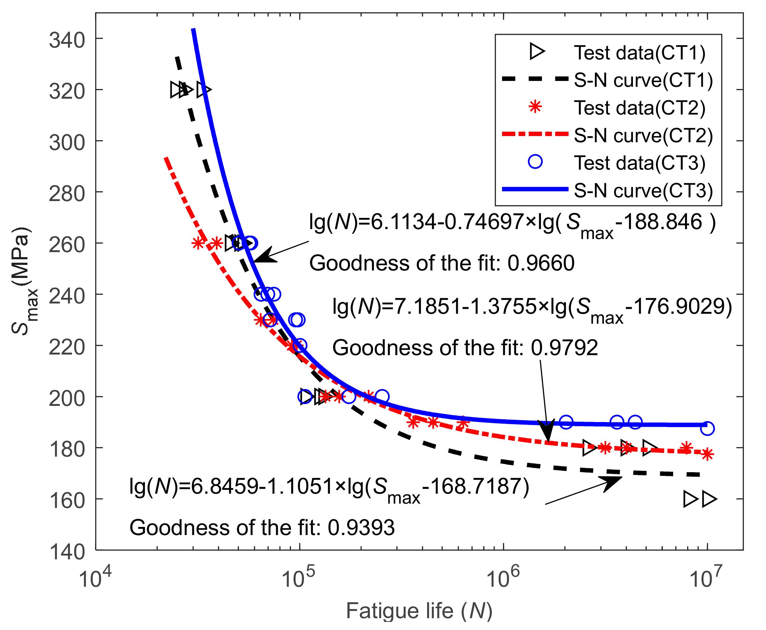
3.2. Effects of Prebending Radii on HCF

As can be seen from the data in Figure 3, The S-N curves of 7075 aluminum alloy under different prebending radii have a significant influence on the fatigue life of the formed alloy. When the prebending radius ρ was 1500 mm, the fatigue life was the longest under the same stress level. Under the higher stress levels (>210 MPa), the fatigue life of the alloy formed with prebending radius 500 mm was longer than that with prebending radius 1000 mm, while under the lower stress levels (<210 MPa), the fatigue life of the alloy formed with the prebending radius 500 mm was the shortest. The results show that increasing the prebending radius contributes to reducing the damage of the alloy under low stress (<210 MPa) and to improving the HCF performance of 7075 aluminum alloy.
As aluminum and aluminum alloys are not commonly considered to have a fatigue limit, the conditioned fatigue limit is usually used in practical engineering applications. According to the method in literature [22], the conditioned fatigue limit is defined as the fatigue life when the number of cycles is 107. The conditional fatigue limits of 7075 aluminum alloy with different prebending radii are calculated and obtained from SN curves, as shown in Table 3, where the data also indicate that the prebending radius has a significant influence on the conditional fatigue limit of the alloy. The conditional fatigue limit of the alloy increased as the preload radius increased. When the prebending radius was 1500 mm, the conditional fatigue limit reaches the maximum value: 188.91 MPa.

3.3. Effects of Prebending Radii on Microstructure

The TEM images of 7075 aluminum alloy at different prebending radii are shown in Figure 4, where the data indicate that the prebending radii have a significant influence on the microstructure of 7075 aluminum alloy. By measuring over 100 precipitates in TEM images, the average precipitate size was 60 nm in width and 80 nm in length in the matrix, which was the largest at a prebending radius of 500 mm, and the width of the precipitate free zone (PFZ) was the widest, approximately 100 nm, as shown in Figure 4c. The PFZ width and precipitate size decrease as the prebending radius increases. When the prebending radius was 1000 mm, the width of PFZ was 81 nm, and the average precipitate size was 55 nm in width and 64 nm in length, as shown in Figure 4b. When the prebending radius was 1500 mm, the width of PFZ was only half of that when the radius was 500 mm, and the average precipitate size was 50 nm in width and 60 nm in length, as shown in Figure 4a.
Previous studies [23] have shown that stress can increase dislocation density, thus accelerating the rate of phase transformation and growth. In addition, the dislocations have a significant effect on fatigue performance: the higher the number of dislocations, the greater the interface energy, and the greater the stress concentration around the dislocations. As can be seen from Figure 4, at a small stress (the prebending radius was 1500 mm), the precipitated phase in the matrix is a finer dispersion than in the other cases. On the one hand, the smaller the size and the more dispersed the precipitated phase, the stronger the combining capacity between the precipitated phase and the matrix, which can result in stronger fracture toughness, hardness and strength [24]. In this experiment, with the increase of the prebending radius, the size of the precipitated phase becomes smaller and the distribution becomes more homogeneous. Therefore, the hardness and tensile properties of the alloy increased. On the other hand, the smaller the size and the more dispersed the precipitated phase, the better the fatigue performance.
In this experiment, the average number and average length of dislocations were measured on an area of 0.93 μm × 0.93 μm of TEM images more than ten times. The stress was the largest at prebending radius of 500 mm, and thus the average density of dislocations was 7.996 × 109 cm−2 and their average length (77.1 nm) of dislocations were also the largest, as shown in Figure 4f. This, together with the fact that the size of the precipitated phase was also the largest, causes the conditional fatigue limit to be the lowest. The average density of dislocations was 5.239 × 109 cm−2 and the average length was 58.6 nm when the prebending radius was 1000 mm, as shown in Figure 4e. When the prebending radius was 1500 mm, the average density of dislocations was 3.86 × 109 cm−2 and the average length (49 nm) of dislocations were smaller than those at the prebending radius of 500 mm and 1000 mm, and the size of precipitated phase was smallest as well, as shown in Figure 4d, so the fatigue life was the highest.

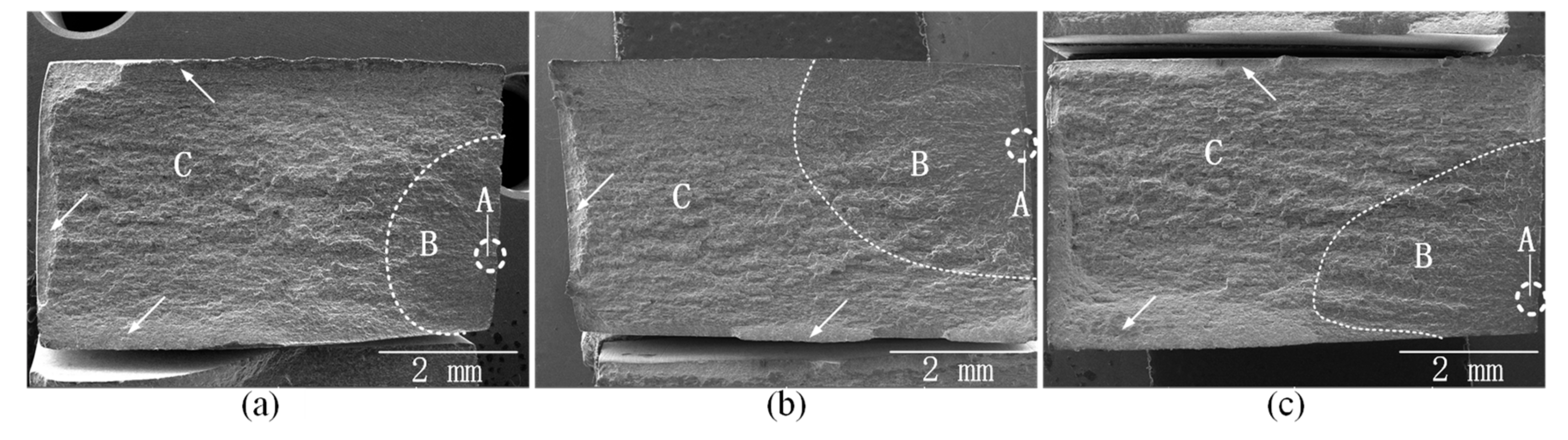
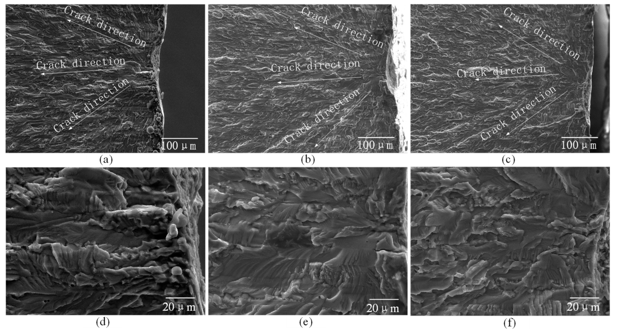
3.4. Effects of Prebending Radii on Fracture Morphology

Under 260 MPa, the fatigue fracture topographies of 7075 aluminum alloy after creep age forming with different prebending radii are shown in Figure 5. The data show that there were three typical regions on fatigue fracture topographies, which are marked by A, B and C, where A is the fatigue crack initiation region, B is the fatigue stable propagation region, and C is the fatigue transient fracture region. Some shear lips appeared at the edge of the specimens, which are represented by the white arrow mark.
Under 260 MPa, the morphologies of the fatigue crack initiation regions of 7075 aluminum alloy after creep age forming with different prebending radii are shown in Figure 6. The data show that radial stripes appear in the fatigue crack initiation regions under low magnification (Figure 6a–c), while under high magnification (Figure 6d–f), many fine steps appear in the fatigue initiation regions, which have smooth surface and many tiny cracks. Those steps are the secondary cracks formed in the nucleation process of the crack, but which lose power.
Under 260 MPa, the SEM morphologies of the fatigue stable propagation regions of 7075 aluminum alloy after creep age forming with different prebending radii are shown in Figure 7. The data indicate that the fracture shows many fatigue striations and furrows. When the prebending radius was 1500 mm, the average width of the fatigue striation was 0.426 μm, obtained by measuring over 5 strips in SEM images. The average fatigue striation width was 0.308 μm when the prebending radius was 1000 mm and 0.368 μm when the prebending radius was 500 mm.
Under 260 MPa, the SEM images of the fatigue transient fracture regions of 7075 aluminum alloy after creep age forming with different prebending radii are shown in Figure 8. As can be seen from Figure 8, the fracture transient fracture regions show that there were both intergranular fractures and transgranular fractures. Intergranular fracture forms the stratified fracture planes on the fracture surface, while transgranular fracture forms dimples on the fracture surface [25]. When the prebending radius was 1500 mm, the dimples of 7075 aluminum alloy fracture were the largest. As the prebending radius decreases, the dimples become progressively smaller. It indicates that the toughness of the alloy decreases with the decrease of the prebending radius, which was consistent with the decrease in the elongation of the alloy.

4. Conclusions

In this paper, three groups of creep age forming experiments of 7075 aluminum alloy under different prebending radii were carried out, and the effects of three prebending radii (500 mm, 1000 mm, and 1500 mm) on the mechanical properties, HCF performance and microstructure of 7075 aluminum alloy after forming were studied. The following conclusions were drawn:
(1) Under the condition of 443 K + 10 h, with the increase of the prebending radius, the hardness, strength, and elongation increased. When the prebending radius was 1500 mm, the maximum value was 187 HV, σb = 568.98 MPa, σ0.2 = 466.51 MPa, δ = 6.12%.
(2) The conditional fatigue limit increases with the increase of the prebending radius. When the prebending radius was 1500 mm, the maximum value was 188.91 MPa.
(3) With the increase of prebending radius, the size and density of precipitated phase become smaller and larger, and the width of PFZ also becomes narrower. In this experiment, when the preloading radius was 500 mm, the width of the PFZ was the largest (100 nm), while when the preloading radius was 1500 mm, the width of the PFZ was the smallest (50 nm).

Author Contributions

D.Y. and Y.L. conceived and designed the experiment; D.Y., J.M. and F.Z. performed the experiments; D.Y., J.M., and F.Z. analyzed the data; Z.F. and Y.L. contributed reagents, materials, and analysis tools; D.Y. wrote and edited the paper; all authors were involved in discussion for the paper.

Funding

This research was funded by the Project Supported by Scientific Research Fund of Hunan Provincial Education Department, grant number 17C0638; National Natural Science Foundation of China, grant number 11702091 and the Natural Science Foundation of Hunan Province of China, grant number 2018JJ3140; Science and Technology Foundation of Changsha, grant number k1705052.

Conflicts of Interest

The authors declare no conflict of interest.

References

  1. Zhu, A.W.; Starke, E.A. Materials aspects of age-forming of Al-xCu Alloys. J. Mater. Process. Technol. 2001, 117, 354–358. [Google Scholar] [CrossRef]
  2. Inforzato, D.J.; Costa, J.P.R.; Fernandez, F.F.; Travessa, D.N. Creep-age forming of AA7475 aluminum panels for aircraft lower wing skin application. Mater. Res. 2012, 15, 596–602. [Google Scholar] [CrossRef] [Green Version]
  3. Liu, C.; Liu, Y.; Li, S.B.; Ma, L.Y.; Zhao, X.Q.; Wang, Q. Effect of creep aging forming on the fatigue crack growth of an AA2524 alloy. Mater. Sci. Eng. A 2018, 725, 375–381. [Google Scholar] [CrossRef]
  4. Brewer, H. Age forming integrally stiffened, aluminum aerospace structures in an autoclave. In Proceedings of the Aircraft Design & Operations Meeting, Seattle, WA, USA, 31 July–2 August 1989. [Google Scholar]
  5. Pitch, E.P.D.; Styles, C.M. Creep age forming of 2024, 8090 and 7449 alloys. Mater. Sci. Forum 2000, 331–337, 455–460. [Google Scholar] [CrossRef]
  6. Huang, X.; Zeng, Y.S. Study on spring back during creep age forming of aluminum alloy 7075. J. Plast. Eng. 2012, 19, 79–82. [Google Scholar] [CrossRef]
  7. Jin, X.; Wan, M.; Li, C. Effect of creep age forming on fatigue for 7B04 aluminum alloy. Forg. Stamp. Technol. 2011, 26, 124–127. [Google Scholar] [CrossRef]
  8. Adachi, T.; Kimura, S.; Nagayama, T. Age forming technology for aircraft wing skin. Mater. Forum 2004, 28, 202–207. [Google Scholar]
  9. Eberl, F.; Gardineer, S.; Campanile, G. Age formable panels for commercial aircraft. Proc. Inst. Mech. Eng. Part G Aerosp. Eng. 2008, 222, 872–886. [Google Scholar] [CrossRef]
  10. Peddieson, J.; Buchanan, G.R. Mathematical modeling of an age-forming process. Math. Comput. Model. 1990, 14, 1057–1060. [Google Scholar] [CrossRef]
  11. Sallah, M.H.; Peddieson, J.; Foroudastan, S. A mathematical model of autoclave age forming. J. Mater. Process. Technol. 1991, 28, 211–219. [Google Scholar] [CrossRef]
  12. Ho, K.C.; Lin, J.; Dean, T.A. Constitutive modeling of primary creep for age forming an aluminum alloy. J. Mater. Process. Technol. 2004, 153, 122–127. [Google Scholar] [CrossRef]
  13. Sarioglu, F.; Orhaner, F.O. Effect of prolonged heating at 130 °C on fatigue crack propagation of 2024 Al alloy in three orientations. Mater. Sci. Eng. A 1998, 248, 115–119. [Google Scholar] [CrossRef]
  14. Bray, G.H.; Glazov, M.; Rioja, R.J.; Li, D.; Gangloff, R.P. Effect of artificial aging on the fatigue crack propagation resistance of 2000 series aluminum alloys. Int. J. Fatigue 2001, 23, S265–S276. [Google Scholar] [CrossRef]
  15. Lumley, R.N.; O’Donnell, R.G.; Polmear, I.J. Enhanced fatigue resistance by under aging an Al-Cu-Mg-Ag alloy. Mater. Forum 2005, 29, 256–261. [Google Scholar]
  16. Chen, G.-Q.; Fu, X.-S.; Zhao, F.; Zhou, W.-L. Microstructures and mechanical properties of 2A12 aluminum alloy after age forming. Trans. Nonferrous Met. Soc. China 2012, 22, 1975–1980. [Google Scholar] [CrossRef]
  17. Yang, D.L.; Liu, Y.L.; Li, S.B.; Ma, L.Y.; Liu, C.; Yi, J.H. Effects of aging temperature on microstructure and high cycle fatigue performance of 7075 aluminum alloy. J. Wuhan Univ. Technol. (Mater. Sci.) 2017, 32, 677–684. [Google Scholar] [CrossRef]
  18. Zhan, L.H.; Li, Y.G.; Huang, M.H. Microstructures and properties of 2124 alloy creep ageing under stress. J. Cent. South Univ. (Sci. Technol.) 2012, 43, 926–931. [Google Scholar]
  19. Zhu, A.W.; Starke, E.A. Stress ageing of Al-xCu alloys: Experiments. Acta Mater. 2001, 49, 2285–2295. [Google Scholar] [CrossRef]
  20. Liu, J.H.; Li, D.; Liu, P.Y.; Guo, B.L.; Zhu, G.W. Effect of ageing and retrogression treatments on mechanical and corrosion properties of 7075 aluminum alloy. Trans. Met. Heat Treat. 2002, 23, 50–53. [Google Scholar] [CrossRef]
  21. Liu, D.H.; Xie, Y.X.; Li, J.C. Influence of process parameters on creep age forming formability of 7075 aluminum alloy sheets. Mater. Sci. Technol. 2015, 23, 50–56. [Google Scholar] [CrossRef]
  22. Yang, D.L.; Liu, Y.L.; Li, S.B.; Yi, J.H.; Tao, J. Investigation of uniaxial asymmetric high-cycle fatigue failure behavior of 7075-T651 Aluminum Alloy Sheet. In Proceedings of the International Conference on Material Science and Applications (ICMSA 2015), Suzhou, China, 13–14 June 2015; Atlantis Press: Paris, France. [Google Scholar] [CrossRef]
  23. Li, C.; Dai, S.L.; Zhang, K.; Ru, J.G. Effect of stress on microstructure and mechanical properties during age forming process of 7050 aluminum alloy. Hangkong Cailiao Xuebao J. Aeronaut. Mater. 2013, 33, 19–23. [Google Scholar] [CrossRef]
  24. Wang, C.H.; Zhang, T.; Yin, H.X.; Lv, Z.F. Effect of aging treatment on microstructure and properties of 7075 aluminum alloy. Heat Treat. Met. 2017, 42, 87–90. [Google Scholar] [CrossRef]
  25. Suresh, S. Fatigue of Materials; Cambridge University Press: Cambridge, UK, 1998; pp. 238–248. [Google Scholar] [CrossRef]
Figure 1. Creep age forming experiment: (a) prebending, (b) aging, and (c) unloading.
Metals 09 00630 g001
Figure 2. Size of the specimens: (a) cutting direction, (b) high cycle fatigue (HCF) specimen, and (c) tensile specimen (unit: mm).
Metals 09 00630 g002
Figure 3. S-N curves of 7075 aluminum alloy at different prebending radii.
Metals 09 00630 g003
Figure 4. TEM microstructure of 7075 aluminum alloy at different prebending radii. (a,d) 1500 mm; (b,e) 1000 mm; (c,f) 500 mm.
Metals 09 00630 g004
Figure 5. Fatigue fracture topography of 7075 aluminum alloy at different prebending radii (Smax = 260 MPa). (a) 1500 mm; (b) 1000 mm; (c) 500 mm.
Metals 09 00630 g005
Figure 6. SEM morphologies of fatigue crack initiation regions of the 7075 aluminum alloy at different prebending radii (Smax = 260 MPa). (a,d) 1500 mm; (b,e) 1000 mm; (c,f) 500 mm.
Metals 09 00630 g006
Figure 7. SEM morphologies of fatigue stability propagation regions of 7075 aluminum alloy at different prebending radii (Smax = 260 MPa). (a) 1500 mm; (b) 1000 mm; (c) 500 mm.
Metals 09 00630 g007
Figure 8. SEM morphologies of fatigue transient fracture region of 7075 aluminum alloy under different prebending radii (Smax = 260 MPa). (a) 1500 mm; (b) 1000 mm; (c) 500 mm.
Metals 09 00630 g008
Table 1. The parameters of the experiments.
Group No.Temperature/KTime/hρ/mm
CT1443101500
CT2443101000
CT344310500
Table 2. Mechanical properties of 7075 aluminum alloy at different preloading radii.
Group No.Prebending Radii ρ/mmAverage Hardness/HVAverage UTS σb/MPaAverage YS σ0.2/MPaAverage
δ/%
CT11500187569.650512.6
CT21000183552.47468.6412.51
CT3500172538.36466.516.12
The standard deviation-7.7715.6421.633.72
Table 3. The conditional fatigue limits of 7075 aluminum alloy at different prebending radii.
Group No.Prebending Radii/mmConditional Fatigue Limits/MPa
CT11500188.91
CT21000178.27
CT3500169.44

