Article

Metastable Al–Si–Ni Alloys for Additive Manufacturing: Structural Stability and Energy Release during Heating

1
Department of Materials Science, Transilvania University of Brasov, 500036 Brasov, Romania
2
Department of Engineering “Enzo Ferrari”, University of Modena and Reggio Emilia, 41100 Modena, Italy
3
Integrated Centre for Environmental Science Studies in the North-East Development Region–CERNESIM, “Al. I. Cuza” University of Iasi, 700506 Iasi, Romania
4
Faculty of Physics, Alexandru Ioan Cuza University, 700506 Iasi, Romania
5
Centre Product Design for Sustainable Development, Transilvania University of Brasov, Eroilor 29, 500036 Brasov, Romania
6
Department of Manufacturing Engineering, Transilvania University of Brasov, 500036 Brasov, Romania
*
Author to whom correspondence should be addressed.
Metals 2019, 9(5), 483; https://doi.org/10.3390/met9050483
Submission received: 26 March 2019 / Revised: 19 April 2019 / Accepted: 23 April 2019 / Published: 26 April 2019

Abstract

:
Rapid solidification with high cooling rates of metal alloys determines both the improvement of mechanical properties, due to the finishing of the structure, as well as obtaining metastable structures in the form of supersaturated or amorphous/nano solid solutions, which could potentially confer the material outstanding properties. It is of particular interest to use the energies released during the heating stage for these materials, due to the potentially lower input energy required to melt/fuse these materials. This phenomenon could add to the development and diversification of additive manufacturing technologies. The paper presents results concerning the structural development and phase transformation of metastable structures from Al–Si–Ni-based alloys, obtained by melt spinning and atomization techniques. It was observed that the structural transformations occurring during the heating process, starting from metastable structures, generate significant amounts of energy. This is of practical importance in the use of metallic powders in additive manufacturing technology, due to potentially reduced energy input.

1. Introduction

Powders with metastable structures capable of releasing significant energy/heat during the heating process could be produced by melt spinning, with subsequent milling. The melt-spinning processing technology provides significantly high cooling rates during solidification.
Generally, rapid solidification leads to a substantial improvement in mechanical properties, compared to conventional alloy processing from the same composition, due to the extension of solid solution limits, microstructure refining, and second-phase dispersion [1,2,3]. Rapid solidification results in a refinement of the microstructure (including grains and secondary phase particles), a reduction in macro and micro segregation, a significant increase in solid state solubility, as well as the formation of unbalanced or metastable phases [4,5].
Due to their good casting capacity, high mechanical strength, low weight, excellent corrosion resistance, and low thermal expansion coefficient, aluminum–silicon (Al–Si) alloys are used in high-end areas such as aerospace, automotive, and electronics industries. Significant efforts have been done to study the microstructure, mechanical properties, and thermal stability of this family of aluminum alloys [6]. In the automotive industry, the importance of Al–Si and Al–Si–X (X = Me) alloys is paramount, especially for certain components of the engine [7].
Because high-rate solidification is a practical way of significantly changing the structure, several methods and techniques have been developed in this field. Among the fast solidification techniques, melt-spinning is an approach with unique advantages in refining the microstructure. The single-roll melt-spinning process has one of the highest melt cooling rates throughout the continuous casting process, the solidification occurring over a time-scale of milliseconds [8]. The major advantage of melt-spinning is the possibility of continuous production of fast-solidified materials in the form of thin ribbons, even on a large industrial scale [3]. The characteristics of the aluminum alloys thus obtained gives them physical, chemical, and mechanical properties different to those obtained by conventional casting [9]. The extended solid solution as well as dispersed particle formation can improve the mechanical strength, wear resistance, and thermal stability of melt-spun alloys [10].
Generally, the metallic powders that are used for additive manufacturing (AM) are obtained by atomization, where the rate of cooling of the metal granules (and hence solidification) is generally in the order of 104–105 °C/s, which includes this process in the category of fast alloy solidification. Research has been carried out on the influence of cooling during atomization on the structure of aluminum–nickel (Al–Ni) alloys [11]. It was found that the development of the phases and the lattice parameters of the different phases vary with the size and composition of the droplets, hence with the cooling rate during the atomization process.
Gas atomization is one of the most common methods of obtaining fine metallic powders, with spherical shapes and homogeneous structures [12]. In a gas atomization process, a stream of hot molten metal performs a heat exchange with high-pressure gas jets, which give rise to high cooling and sub-cooling speeds for the atomized metal droplets. The produced powder particles exhibit a low segregation and a very fine microstructure, which improves the properties of the material, such as mechanical strength, durability, hardness, and corrosion resistance [13].
Materials with metastable structures based on high-performance alloys have been studied, by combining new technologies and new chemical compositions. It was observed that the mechanical properties of aluminum alloys can be significantly improved by rapid solidification (RS) during the atomization process in gas, as well as applying powder metallurgy (PM) techniques [14].
Laser-based AM technologies involve selective melting of cross-sections onto a powder bed that is lowered incrementally to build the part layer upon layer. A laser beam is focused onto the powder bed and used as a melting tool, driven along a toolpath by mirrors or lenses. One of the key factors affecting dimensional accuracy of laser-based AM processes is the minimum spot diameter. The obvious consequence is an increasing adoption by system manufacturers of high-energy beams, to be focused into always smaller spots, while preserving the capability to process high-melting alloys. Consequently, in order to obtain a fully melt pool, higher energy input is generally needed. Developing new materials which can be melted/fused with lower input power is of high importance.
In order to reduce the amount of heat required for the laser processing of the alloy and thus to reduce the required laser power, it is necessary that a heat-generating phenomenon occurs when the alloy is heated—in this case, this heat should be subtracted from the heat required for fusion. In order for the heating of the alloy to produce exothermal effects, it is necessary that: (i) The structure is a non-equilibrium, metastable, or amorphous structure, or (ii) the alloy has in its structure a supersaturated solid solution, which, upon heating, decomposes, followed by the formation of intermetallic compounds, which should produce positive energy effects.
In the present paper, the authors highlight the influence of the processing technologies on Al–Si–Ni alloy structures. To date, the number of reports concerning this system (Al–Si–Ni) is significantly low. Moreover, only a limited number of compositions was studied. The aim of the research was to establish correlations between the obtained metastable structures (amorphous/nanostructured) and the thermal effects that arise from the heating process of these materials, with certain potential applications in the AM technology.

2. Materials and Methods

Al–Si–Ni alloys with different elemental concentrations were prepared in an electric furnace, heated with silicon carbide resistors, in graphite crucibles, under an initially powdered protective flux layer. The protective flux was added on the melt pool in powder form, in order to deoxidize, refine, and decontaminate the molten alloy. Aluminum, Al-Si22, and Ni80 pre-alloys (nickel blended with flux) were used to obtain the bulk alloys. The chemical composition of the produced alloys is shown in Table 1, along with the sample variants obtained for each alloy.
Thin alloy ribbons were obtained by melt-spinning. The alloys were melted inside a perforated Al2O3 crucible, using a copper induction coil. The diameter of the molten metal outlet was 1 mm, positioned at 1 mm distance from the copper wheel. The copper disk rotation speed was 2600 rpm (resulting in a peripheral speed of about 28 m/s). In order to avoid contamination/oxidation of the melt, the crucible was continuously purged with argon (Pargon = 1 bar). Once the alloy was melted, the argon pressure was increased to 8 bars, thus causing the expulsion of the molten alloy on the spinning copper disk. The dimensions of the melt-spun ribbons were: Al79Si11Ni10 alloy, thickness 49 ± 6 µm, width 1.8 ± 0.4 mm; Al67Si18Ni15 thickness 52 ± 8 µm, width 2.4 ± 0.6 mm.
In order to observe the influence of the cooling speed on the structure, for the preparation of Al79Si11Ni10 powder granules by atomization, the same copper induction coil, containing the alumina crucible, was used, but this time the molten alloy was cooled/solidified using a gas atomizer. The atomization was done in water at a pressure of 4 bar using an atomizer with the following characteristics: 16 equidistant discharge outlets of water, 1 mm in diameter, fluid angle α = 45°, water temperature of 20 °C, 2 mm molten metal jet diameter. The average granule dimension obtained by atomization was 360 ± 80 µm.
The samples, which were later-on analyzed, are separated as follows: Al79Si11Ni10 as-cast (referred to as “bulk”), melt-spun (referred to as “ribbons”), and atomized (referred to as “granules”); Al67Si18Ni15 as-cast (referred to as “bulk”), and melt-spun (referred to as “ribbons”).
The structural analysis of the bulk, melt-spun, and atomized samples was performed on an Omnimet-Buehler structural analysis system (Buehler, Esslingen am Neckar, Germany), equipped with a Nikon metallographic microscope (up to 1000× magnification, Nikon Eclipse MA100, Nikon Co, Tokyo, Japan) and a software suitable for quantitative structural analysis (NIS Element, version S4.30.01, Nikon Co., Tokyo, Japan).
The structural properties of the bulk and melt-spun samples (1 cm long strips) were investigated using X-Ray diffraction (Shimadzu LabX XRD-600 diffractometer, Shimadzu, Tokyo, Japan), with Cu Kα radiation (λ = 1.54059 Å). The samples were analyzed in ambient atmosphere, within 2°–90° 2θ range, with a scanning angle step of 0.02° and a 2 deg/min count time.
The samples were observed with a scanning electron microscope (SEM, Quanta FEI, Eindhoven, The Netherland) operated in high vacuum mode, equipped with an X-ray energy dispersion spectroscopy system (X-EDS, INCA Oxford Instruments, Abingdon, UK) for chemical micro-analysis.
The structural stability of the samples was studied by differential scanning calorimetry (DSC) analysis on a MAIA DSC 200F3 machine (Netzsch, Selb, Germany) produced by Netzsch, with a heating/cooling rate of 10 °C/min in nitrogen atmosphere, up to the maximum temperature of 600 °C, and data processing was done using the Netzsch Proteus Analysis software (5.2.1/2011, Netzsch, Selb, Germany). For comparison purposes, a commercially available industrial powder (F357-type (AlSi10Mg equivalent), EOS Gmbh) was also analyzed.
The crystallization temperatures of the samples were studied on a F3 Jupiter STA/TG/DTA (Netzsch, Selb, Germany), with a heating/cooling rate of 10 °C/min in argon atmosphere, up to the maximum temperature of 1050 °C, and data processing was done using the Netzsch Proteus Analysis software (5.2.1/2011, Netzsch, Selb, Germany). The calibration of the instrument was done before each measuring session.
In order to assess some mechanical properties (hardness–H and elastic modulus–E) of the Al–Si–Ni alloys, both in bulk form and fast-cooled samples, instrumented indentation measurements were performed, using a CSM Instruments/Anton Paar NHT2 module (CSM Instruments/Anton Paar, Pesseux, Switzerland), equipped with a diamond Berkovich indenter. The instrumented indentation parameters were: maximum load 20 mN, loading rate 40 mN/min, unloading rate 40 mN/min, dwell time 10 s. At least 20 measurements were performed on each sample, and the results were averaged. The samples (as-cast bulk fragments, melt-spun ribbons, and atomized granules) were embedded in low-contraction resin, in order to minimize the effect on the final results, followed by mechanical polishing to a mirror-like finish. Moreover, in order to assess the microhardness of the bulk samples, a Vickers microhardness tester (Future-Tech FM700, Kawasaki, Japan) was used (FM 700), with the following conditions: 100 gf applied load, 15 s dwell time. At least 10 indentations were performed on the bulk alloys, and the results were averaged. In order to be able to compare the results with the data from the literature, the Vickers values were converted to Brinell units.

3. Results and Discussion

3.1. Cooling Rate Estimation

The amorphous/metastable structure of aluminum alloys is influenced by both the solidification rate and the chemical composition. There are numerous studies on the amorphization capacity of the Al–Ni–Ti ternary system [15,16,17,18]. However, with respect to alloys in the Al–Si–Ni system, the data are significantly scarce. According to the reports from the literature, the compositions that would allow one to obtain amorphous structures in the Al–Si–Ni system are located in a well-defined area of the ternary diagram, in the ternary Al-reach corner (compositions with more than 50% Al and Ni ranging from 5 to 20%) [18]. The alloys presented in Table 1, namely Al79Si11Ni10 and Al67Si18Ni15, fall within the compositions most susceptible to produce amorphous structures.
The position of the Al79Si11Ni10 alloy in the vertical projection of the Al–Si–Ni diagram for 10% Ni indicates the thermal conditions are met during the alloy processing by melting, spinning, and atomizing, as noticed in Figure 1. The large interval of solidification needs to be noticed, a critical parameter concerning alloys with the tendency to form amorphous structures. It is worth mentioning that this interval is even larger for the Al67Si18Ni15 composition, which creates several difficulties during the alloy processing.
As previously mentioned, the second essential factor in obtaining the amorphous structure is a high solidification rate. Cohen, Kear, and Mehrabian place the melt-spinning and gas-atomization processes in the category of high solidification rates [19].
The first problem that needs to be assessed is the estimation of the cooling speeds provided by the two processing technologies. Both in the case of melt spinning and gas atomization, there are numerous studies on how the cooling rate should be assessed. However, it is very difficult to establish an exact mathematical relationship that determines the cooling rate due to the complexity of the phenomena occurring at the interface of molten metal-rotating disc or molten metal-atomizing fluid. All approaches start from the heat exchange between the two environments. However, trying to establish an exact relationship that describes the process would be problematic, due to several factors that should be considered.
The estimation of the cooling rate is most often done using an empirical relationship [20] which links the distance between the branches of the dendrite and the solidification rate. The relationship is used by several authors at this time to estimate the cooling rate [21,22]:
d = A × vn
where d is the distance between dendrite branches (dendritic parameter) in μm, v is the cooling rate in °C/s, and A and n are material-dependent constants.
Considering the dendritic parameter for Al79Si11Ni10 alloy atomized particles, which is between 2 and 5 μm (observable in Figure 2 and Figure 3, where single atomized particles can be observed), and the values of constants A and n [23] for the same alloy, a cooling rate value of about 5 × 10⁵ °C/s was obtained.
In the case of atomization, the cooling rate is an essential factor that influences the microstructure of the obtained powder. Currently, the cooling formula (dT/dt) Equation (2) is being used for rapid solidification that occurs during atomizing. The formula was developed by He et al. [24]:
| d T d t | = 12 ρ c p ( T d T f ) k g d 2
where ρ is the melt alloy droplet density, Cp—the specific heat, Td—the atomization temperature of the alloy (it is approximated to be the casting temperature), Tf—the atomization fluid temperature, kg—the atomization fluid thermal conductivity, d—the droplet diameter.
Using Equation (2) should not cause any issues, because it does not depend on parameters that are difficult to obtain, such as solidification time, nucleation speed, heat quantity, etc. Considering the following values: ρalloy = 2650 kg/m3; cp alloy = 920 J/kgK; Td = 900 °C; Tf = 20 °C; kg = 0.598 W/mK; and d~70 μm, results from Equation (2), a cooling rate value of about 5.24 × 10⁵ °C/s, is comparable to literature data.
Under the same conditions, the atomized alloy using argon as a spraying gas cools at a rate (similarly calculated) of only 1.4 × 10⁴ °C/s (due to the much lower thermal conductivity of argon, compared to water) which is not sufficient for the amorphization of the powder.
For verification, applying the relationship between the dendritic parameter and the cooling rate for the water-atomized powder (Figure 3) results in a cooling rate value of 105 to 106 °C/s, as previously calculated.
It can be seen that the microstructure comprises intermetallic compounds of the NiAl3 type (mid-grey elongated phases and dark grey phase), which are formed directly from the liquid and from the eutectic phases (light grey region). As the cooling rate increases (with the increase of spray water pressure), the dimensions of the intermetallic compounds become smaller, as it can be observed in Figure 3a. It should be noted that due to the local cooling conditions, in the fine structure, there are dendrites of larger dimensions (d ≈ 7–10 μm, Figure 3a). For comparison, the structure of a powder granule obtained under industrial conditions by gas atomization using argon as a spraying gas can be observed in Figure 3b. The presence of a fine-grained structure can be attributed to rapid solidification during melt spinning which induces the formation of a high density of nuclei.
Due to the supplementary refinement of the structure, during the melt-spinning process, the previously presented methodology to calculate the cooling rate cannot be implemented since the dendrites are no longer visible, regardless of magnification. Surface images will be presented in the morphology and chemical composition section, obtained by scanning electron microscopy.

3.2. Structural Analysis

The diffractograms for the bulk compositions and those of the melt-spun ribbons (selected samples, 1 cm long fragments), can be observed in Figure 4. One can observe that for the Al79Si11Ni10 alloy, a certain degree of structural refinement occurs, considering that the peak intensities generally are decreasing, as well as due to the appearance of broad diffraction bands, which suggests the formation of a limited number of small crystallites. Another phenomenon that was observed is the peak broadening, noticed on the diffraction pattern of the melt-spun Al79Si11Ni10 alloy ribbon. Generally, peak broadening in an XRD pattern can be attributed to three factors: (i) Small size of the diffracted crystallites (i.e., coherent domains), (ii) micro-strain caused primarily by dislocations, and (iii) instrumental broadening. Considering that the patterns were obtained in identical conditions, the effect of instrumental broadening would be similar on the bulk Al79Si11Ni10 alloy, as well as the melt-spun Al79Si11Ni10 alloy ribbon diffraction patterns. Consequently, the first two factors should be further considered in regards to the mechanical properties evolution, presented in Section 3.5.
The situation is different in case of the Al67Si18Ni15 alloy, where, after the melt-spinning process, the diffraction peaks disappear, with the exception of a broad band in the region 10–15 deg. This observation leads one to conclude that the structure is quasi-amorphous, not in its entirety, but close to 100%. In the case of both alloy compositions, multiple diffraction peaks and the overlapping of several potential phases can be observed. The main difference between the two alloy compositions is that the Al67Si18Ni15 alloy diffraction pattern exhibits the presence of the Al3Ni2 compound, while the Al79Si11Ni10 alloy diffraction pattern does not.
The variation of the crystallite size as function of cooling rate for the Al79Si11Ni10 for the bulk alloy and melt-spun ribbons can be seen in Figure 5. The crystallite size for the higher intensity diffraction peaks was calculated with the Scherrer equation [25]. The structural refinement is obvious, for all the phases that were analyzed, with as high as 55% reduction in size for the (311) direction for the melt-spun ribbon.

3.3. Morphology and Chemical Composition

Scanning electron microscopy (SEM) analyses were carried out on the materials (bulk fragments and melt-spun ribbons), embedded in a conductive carbon resin. Figure 6 shows typical microstructures observed for the Al79Si11Ni10 alloy, in bulk form. According to the phase equilibrium diagram, the structure is composed of the AlNi3 intermetallic compound, solidified from the liquid phase, and the eutectic one (Al + Ni2(Al1-xSix)3). The surface chemical mapping from Figure 6 confirms the predicted structure. The AlNi3 intermetallic compound is located in the lighter regions, where the Ni content is prevalent, and it is characterized by increased fragility. The eutectic is located in the darker regions on the SEM micrographs, where a significantly higher Al content is clearly visible. Figure 7 shows the microstructure of the Al67Si18Ni15 alloy in bulk form. The main difference between this composition and the Al79Si11Ni10 alloy is the presence of the Ni2(Al1-xSix)3 phase, which crystalizes firstly, before the NiAl3 intermetallic compound. The Ni-richer compound was confirmed from the XRD analysis. The darker regions represent the eutectic of this alloy composition, composed of NiAl3, elemental Al and Si. The mid-gray regions are representative for the NiAl3 compound.
Figure 8 represents the surface morphology, after mechanical polishing, of the as-cast melt-spun ribbons, as seen in Figure 8a,c, for the Al79Si11Ni10 and Al67Si18Ni15 alloys, and of the thermally treated melt-spun ribbons, as seen in Figure 8b,d. The thermal treatment consisted of heating the as-cast melt-spun ribbons, in argon atmosphere, past the phase transformation temperatures noticed on the DSC curves (Tmax = 400 °C), presented in Section 3.4 (thermal analysis). The surface morphology of the as-cast melt-spun ribbons confirms the observations obtained from the XRD analysis. The Al79Si11Ni10 sample exhibits small crystalline dendritic structures, their number seems to increase after the thermal treatment (Figure 8b). The surface of the Al67Si18Ni15 melt-spun ribbon, after mechanical polishing, is featureless and no signs of crystalline grains can be observed, thus confirming the amorphous nature of this material, shown also by the XRD results. However, after the thermal treatment, lighter dendritic crystalline grains appear in the material, due to the phase transformation induced by the rise in temperature.
The surface chemical composition on the dark and light regions shown in Figure 6, Figure 7 and Figure 8 is presented in Table 2. The results are in good agreement with the predicted phases from the equilibrium diagrams. The bulk variants of the alloys are comprised, as mentioned before, from the Al3Ni intermetallic compound, surrounded by the eutectic matrix, while in the case of the Al67Si18Ni15 alloy, the second intermetallic compound is present (spectrum 1) in the Ni2(Al1-xSix)3 form. The deviations in composition exhibited by the melt-spun ribbons, either in as-cast form or after heat treatment, especially for the Al67Si18Ni15 alloy, could be attributed to potential inhomogeneities or elemental segregations in the melt before casting.

3.4. Thermal Analysis

The melting/crystallization temperatures were assessed by differential thermal analysis. The DTA curves for the bulk alloys are shown in Figure 9, as function of the temperature, in the 500–800 °C domain. Regarding the Al79Si11Ni10 alloy, the eutectic (Al + Ni2(Al1-xSix)3) exhibits the melting temperature of 575.3 °C, in close agreement with the phase diagram. Complete melting of the alloy, comprised of the liquid phase and the AlNi3 intermetallic compound, occurs over 700 °C. The difference in terms of structure for the Al67Si18Ni15 alloy, compared to the Al79Si11Ni10 alloy is clearly visible on the DTA curve, as well. One can notice that the melting temperature of the eutectic is located at 569.2 °C, followed by the melting point of the NiAl3 compound, at 658.4 °C, and finally of the Ni2(Al1-xSix)3 phase intermetallic compound, mixed with the liquid phase. No other peaks, which signify either exo- or endothermal transformations, were observed on the bulk material. In contrast, the rapidly cooled materials (melt-spun ribbons and atomized granules) exhibit exothermal peaks.
An alloy with an amorphous (metastable) structure undergoing a heating process should exhibit a series of structural transformations that would bring the structure close to equilibrium (the structure obtained under ordinary solidification conditions by gravity casting). In the case of the analyzed alloys, this transformation of the metastable structure occurs in the range 50–150 °C. The phenomenon is confirmed by the DSC curves (Figure 10) for the Al79Si11Ni10 alloy, by a peak at 85.3 °C. The energy released by this transformation, 167.6 J/g, represents approximately 32% of the theoretical value of the energy consumed for melting the alloy, determined based on the chemical composition (520 J/g). The situation is slightly different for the Al67Si18Ni15 alloy, which exhibits two exothermal peaks (185.4 °C and 316.4 °C) but with lower energy values (the sum of the two energies is close to that of the Al79Si11Ni10 alloy).
There are situations when the obtained structure, both in the case of melt-spinning and atomizing materials, is not entirely amorphous. However, the high cooling rate favors the formation of supersaturated solid solutions. Heating these supersaturated solid solutions can cause their decomposition and the formation of intermetallic compounds, generally accompanied by exothermal reactions. As seen in Figure 10, this phenomenon is noticeable in the range of 180–300 °C and occurs with an energy release. The significant increase in cooling rate is translated in a qualitative leap in finishing the structure by forming metastable/amorphous structures. The transformation of the metastable state to a stable structure, as well as the formation of intermetallic compounds during heating, was emphasized by DSC analyses. The energy released during additive manufacturing technologies should have positive effects on reducing the power of the laser or increasing the productivity.

3.5. Mechanical Properties

Considering that the proposed aluminum-based alloys are not standardized, their industrial use is highly dependent on their mechanical characteristics. Similar to conventional (subtractive) manufacturing, the parts manufactured by AM technologies must comply to the requirements of the particular application, in terms of mechanical behavior, corrosion resistance, and so forth. Moreover, many methods of additive manufacturing require subsequent heat treatment of the manufactured components, or hot isostatic pressing (HIP). One of the primary mechanical characteristics of a material is its hardness, which can give a measure of the resistance to plastic deformation. Consequently, hardness measurements were performed on the bulk and melt-spun Al79Si11Ni10 and Al67Si18Ni15 alloys, in comparison to the values obtained on the standardized AlSi10Mg alloy granules. From the graph in Figure 11, it can be observed that the bulk Al–Si–Ni alloys exhibit hardness values relatively close to those exhibited by the AlSi10Mg material, while the melt-spun ribbons and the atomized granules are significantly harder. Generally, most nanocrystalline or amorphous materials are often extremely hard and brittle, with low tensile ductility and small elongation to failure, as a result of the absence of strain hardening. Instrumented indentation measurements with a Berkovich diamond tip were performed on the samples, in bulk and melt-spun ribbon form. Due to the inhomogeneous nature of the bulk samples, in terms of crystalline structure, several matrix indentation protocols were performed, in order to better assess some of the mechanical characteristics of the material. Representative protocols are presented in Figure 12 and Figure 13, for the Al79Si11Ni10 and Al67Si18Ni15 bulk alloys. One can notice the presence of the same phases observed on the SEM micrographs, the intermetallic compounds surrounded by the eutectic matrix, each with different properties in terms of hardness or elastic modulus. This phenomenon is confirmed by the significant difference in size of the diamond tip imprints.
Due to the increased homogeneity of the melt-spun ribbons, the variation of the indentation hardness and the indentation elastic modulus is significantly lower, thus allowing further predictions to be made. The H/E ratio, called the elastic strain to failure, gives information on the wear resistance of the material. Higher values for this ratio, meaning a combination of high hardness and low elastic modulus, would confer the material increased fracture toughness. Moreover, the H3/E2 ratio is an indicator regarding the material′s resistance against plastic deformation. Lower values of this ratio signify a poor resistance to plastic deformation. The values of these ratios, along with the indentation hardness and elastic modulus values are presented in Table 3. The Poisson ratio used for the Oliver and Pharr calculation of the elastic modulus was set at 0.32, the value exhibited by the as-cast AlSi10Mg standardized alloy.
From the data in Table 3, it can be concluded that the Al67Si18Ni15 melt-spun variant is characterized by increased fracture toughness, better wear resistance, and adequate resistance to plastic deformation, while the Al79Si11Ni10 melt-spun ribbons and the Al67Si18Ni15 atomized variant exhibit significantly poorer characteristics. Nevertheless, it can be concluded that by altering the chemical composition and the processing parameters of these two ternary alloys, one can obtain usable and adequate characteristics.

4. Conclusions

Samples of Al79Si11Ni10 and Al67Si18Ni15 were prepared by melt spinning and atomization with high cooling speeds (105–106 °C/s), which were studied in terms of their structure. As the cooling rate increases, the dendritic alloy parameter decreases. The significant increase in cooling speed results in a qualitative leap in finishing the structure by forming metastable/amorphous structures.
The transformation of the metastable state as well as the formation of the intermetallic compounds during heating were highlighted by DSC analyses. These structural transformations generate significant amounts of energy, representing 5%–32% of the melting energy (melting heat). This is of practical importance in the use of metallic powders in AM technology. The energy released during the processing of these materials could have positive effects on reducing the power of the laser used or increasing plant productivity.

Author Contributions

Conceptualization, T.B., B.V., and D.C.; data curation, T.B., B.V., D.C., I.G., M.A.P., and C.G.; formal analysis, T.B., B.V., D.C., A.N., A.G., E.B., G.B., I-L.V., M.A.P., C.G., and M.C.; funding acquisition: A.G.; investigation: C.G.; methodology: D.C., and M.A.P. project administration: E.B.; resources, S.M., and D.M.; writing—original draft preparation, T.B., B.V., D.C., I-L.V., and L.P.; writing—review and editing, D.C., I.G., B.V., and T.B.

Funding

This project has received funding from the European Union′s Horizon 2020 research and innovation programme under grant agreement No. 723699. We hereby acknowledge the structural founds project PRO-DD (POS-CCE, O.2.2.1., ID 123, SMIS 2637, ctr. No. 11/2009) for providing some of the infrastructure used in this work.

Conflicts of Interest

The authors declare no conflict of interest.

References

  1. Xu, C.L.; Wang, H.Y.; Qiu, F.; Yang, Y.F.; Jiang, Q.C. Cooling rate and microstructure of rapidly solidified Al–20 wt.% Si alloy. Mater. Sci. Eng. A 2006, 417, 275–280. [Google Scholar] [CrossRef]
  2. Chen, Z.; Lei, Y.; Zhang, H. Structure and properties of nanostructured A357 alloy produced by meltspinning compared with direct chill ingot. J. Alloys Compd. 2011, 509, 7473–7477. [Google Scholar] [CrossRef]
  3. Jassim, A.K.; Hammood, A.S. Single Roll Melt Spinning Technique Applied as a Sustainable Forming Process to Produce Very Thin Ribbons of 5052 and 5083 Al-Mg Alloys Directly from Liquid State. Procedia CIRP 2016, 40, 133–137. [Google Scholar] [CrossRef] [Green Version]
  4. Lin, Y.; Wu, B.; Li, S.; Mao, S.; Liu, X.; Zhang, Y.; Wang, L. The quantitative relationship between microstructure and mechanical property of a melt spun Al–Mg alloy. Mater. Sci. Eng. A 2015, 621, 212–217. [Google Scholar] [CrossRef]
  5. Lin, Y.; Mao, S.; Yan, Z.; Zhang, Y.; Wang, L. The enhanced microhardness in a rapidly solidified Al alloy. Mater. Sci. Eng. A 2017, 692, 182–191. [Google Scholar] [CrossRef]
  6. Dong, X.; He, L.; Li, P. Gradient microstructure and multiple mechanical properties of AlSi9Cu alloy ribbon produced by melt spinning. J. Alloys Compd. 2014, 612, 20–25. [Google Scholar] [CrossRef]
  7. Karakose, E.; Karaaslan, T.; Keskin, M.; Uzun, O. Microstructural evolution and microhardness of a melt-spunAl–6Ni–2Cu–1Si (in wt.%) alloy. J. Mater. Process. Technol. 2008, 195, 58–62. [Google Scholar] [CrossRef]
  8. Izadinia, M.; Dehghani, K. Structure and properties of nanostructured Cu-13.2Al-5.1Ni shape memory alloy produced by melt spinning. Trans. Nonferrous Met. Soc. China 2011, 21, 2037–2043. [Google Scholar] [CrossRef]
  9. Ma, J.; Ren, F.; Wang, G.; Yi, X.; Li, Y.; Wen, J. Electrochemical performance of melt-spinning Al-Mg-Sn based anode alloys. Int. J. Hydrogen Energy 2017, 42, 11654–11661. [Google Scholar] [CrossRef]
  10. Rajabi, M.; Simchi, A.; Davami, P. Microstructure and mechanical properties of Al–20Si–5Fe–2X (X = Cu, Ni, Cr) alloys produced by melt-spinning. Mater. Sci. Eng. A 2008, 492, 443–449. [Google Scholar] [CrossRef]
  11. Tourret, D.; Reinhart, G.; Gandin, C.-A.; Iles, G.N.; Dahlborg, U.; Calvo-Dahlborg, M.; Bao, C.M. Gas atomization of Al–Ni powders: Solidification modeling and neutron diffraction analysis. Acta Mater. 2011, 59, 6658–6669. [Google Scholar] [CrossRef]
  12. Ding, P.; Mao, A.; Zhang, X.; Jin, X.; Wang, B.; Liu, M.; Gu, X. Preparation, characterization and properties of multicomponentAlCoCrFeNi2.1 powder by gas atomization method. J. Alloys Compd. 2017, 721, 609–614. [Google Scholar] [CrossRef]
  13. Li, X.; Fritsching, U. Process modeling pressure-swirl-gas-atomization for metal powder production. J. Mater. Process. Technol. 2017, 239, 1–17. [Google Scholar] [CrossRef]
  14. Wang, E.R.; Hui, X.D.; Wang, S.S.; Zhao, Y.F.; Chen, G.L. Microstructure and mechanical properties of Al–Si–Ni–Ce alloys prepared by gas-atomization spark plasma sintering and hot-extrusion. Mater. Sci. Eng. A 2011, 528, 5764–5771. [Google Scholar] [CrossRef]
  15. Kim, D.H.; Kim, W.T.; Kim, D.H. Formation and crystallization of Al–Ni–Ti amorphous alloys. Mater. Sci. Eng. A 2004, 385, 44–53. [Google Scholar] [CrossRef]
  16. Shi, J.; Zheng, A.; Lin, Z.; Chen, R.; Zheng, J.; Cao, Z. Effect of process control agent on alloying andmechanical behavior of L21 phase Ni–Ti–Al alloys. Mater. Sci. Eng. A 2019, 740–741, 130–136. [Google Scholar] [CrossRef]
  17. Chen, H.; Kong, D. Effects of laser remelting speeds on microstructure, immersion corrosion, and electrochemical corrosion of arc–sprayed amorphous Al–Ti–Ni coatings. J. Alloys Compd. 2019, 771, 584–594. [Google Scholar] [CrossRef]
  18. Fabrichnaya, O.; Beuers, G.; Bätzner, C.; Lukas, H.L. Al-Ni-Si (Aluminium-Nickel-Silicon). In Light Metal Systems. Part 3. Landolt-Börnstein-Group IV Physical Chemistry (Numerical Data and Functional Relationships in Science and Technology); Effenberg, G., Ilyenko, S., Eds.; Springer: Berlin/Heidelberg, Germany, 2005; Volume 11A3. [Google Scholar]
  19. Cohen, M. Advancing Materials Research; Psaras, P.A., Langford, H.D., Eds.; National Academy Press: Washington, DC, USA, 1987; p. 57. [Google Scholar]
  20. Spear, R.E.; Gardner, G.R. Dendrite Cell Size. AFS Trans. 1963, 71, 209–215. [Google Scholar]
  21. Granger, D.A. Ingot Casting in the Aluminum Industry. Treatise Mater. Sci. Technol. 1989, 31, 109–135. [Google Scholar] [CrossRef]
  22. Shivkumar, S.; Wang, L.; Apelian, D. Molten Metal Processing of Advanced Cast Aluminum Alloys. JOM 1991, 43, 26–32. [Google Scholar] [CrossRef]
  23. Şmakov Iu, V.; Zenina, M.V.; Riabov, I.V. Sovremennoje sostoianie i dalnejichee razvitie porchnevah splavov na Al-osnove. Liteino Prod. 2000, 11, 3. [Google Scholar]
  24. He, S.; Liu, Y.; Guo, S. Cooling rate calculation of non-equilibrium aluminum alloy powders prepared by gas atomization. Rare Metal Mat. Eng. 2009, 38, 353–356. [Google Scholar]
  25. Scherrer, P. Bestimmung der Grosse und der Inneren Struktur von Kolloidteilchen Mittels Rontgenstrahlen, Nachrichten von der Gesellschaft der Wissenschaften, Göttinger. Math. Phys. 1918, 2, 98–100. [Google Scholar]
Figure 1. The position of Al79Si11Ni10 alloy in vertical projection of ternary diagram for 10% nickel [18]. The deep eutectic, noticed for the 11% Si position, should benefit in the glass-formation capacity of the alloy.
Metals 09 00483 g001
Figure 2. Metallographic structure of a powder particle obtained by atomization in argon, from the Al79Si11Ni10 alloy.
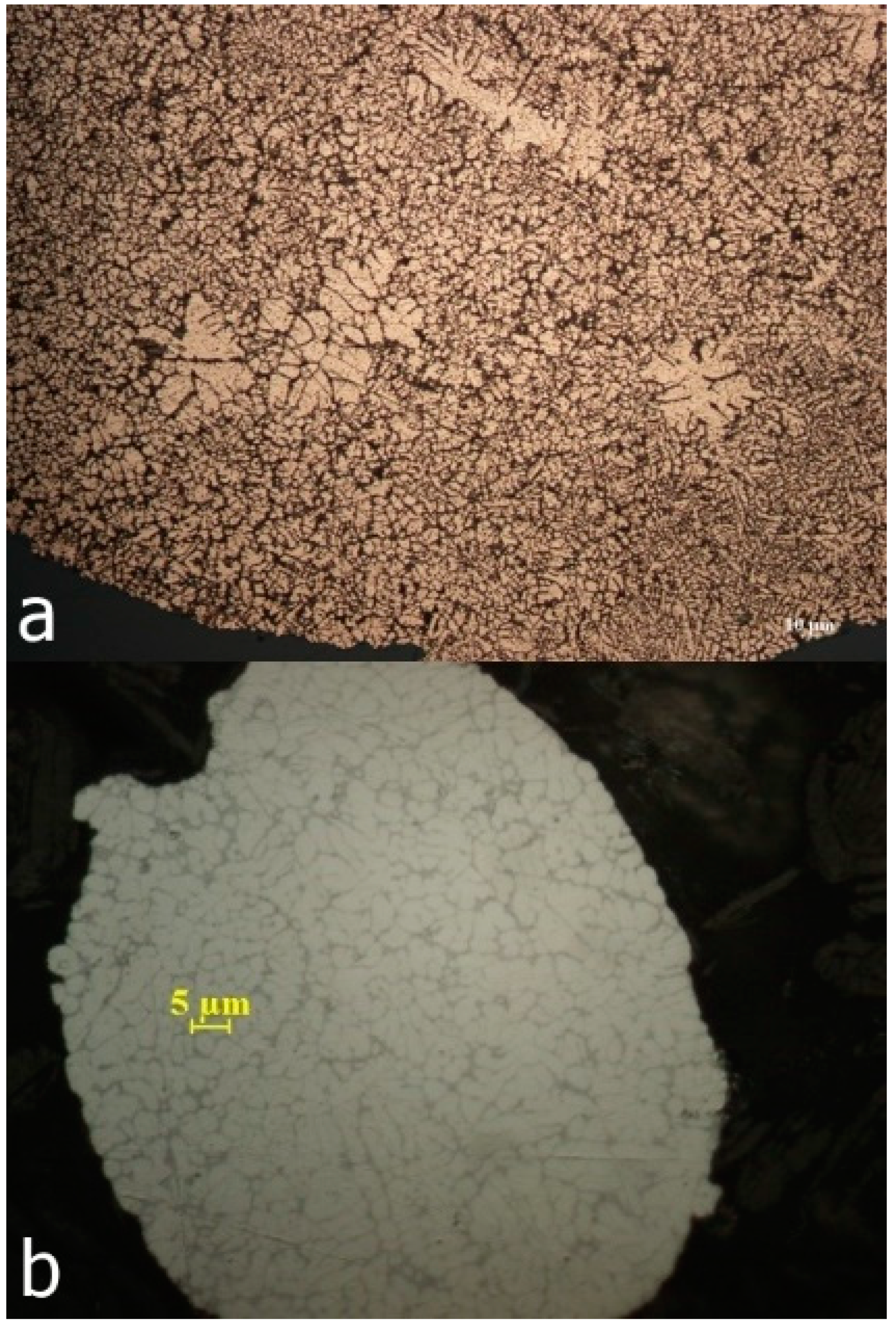
Metals 09 00483 g002
Figure 3. Powder structure obtained by atomization of Al79Si11Ni10 alloy with high pressure, in water (a); the structure of commercially available powder (b).
Metals 09 00483 g003
Figure 4. 
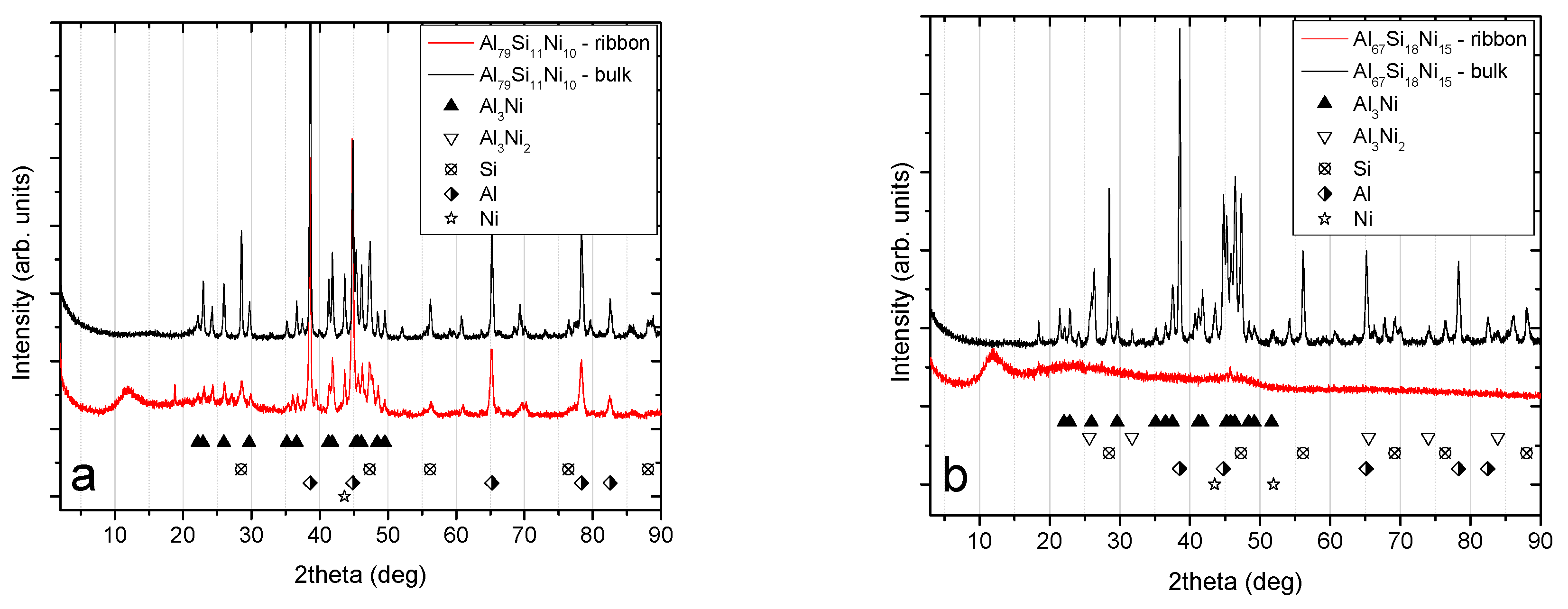
X-ray diffraction patterns for the bulk and melt-spun alloys: (a) Patterns for the Al79Si11Ni10 bulk and melt-spun ribbons; (b) patterns for the Al67Si18Ni15 bulk and melt-spun ribbons.
Metals 09 00483 g004
Figure 5. Crystallite size of different phases of Al79Si11Ni10 in bulk and melt-spun ribbon form. The refinement of the structure is evident for the melt-spun ribbons, extrapolated from the lower crystallite size for all phases.
Metals 09 00483 g005
Figure 6. Surface morphology and chemical composition of Al79Si11Ni10 in bulk form. The segregation of the elements is noticeable, and it is linked to the structural development of the alloy.
Metals 09 00483 g006
Figure 7. Surface morphology and chemical composition of Al67Si18Ni15 in bulk form. The segregation of the elements is noticeable, and it is linked to the structural development of the alloy.
Metals 09 00483 g007
Figure 8. Surface morphology of melt-spun ribbons from Al79Si11Ni10 ((a) as-cast; (b) after heat treatment) and Al67Si18Ni15 ((c) as-cast; (d) after heat treatment).
Metals 09 00483 g008
Figure 9. Differential thermal analysis (DTA) heating curves for the Al79Si11Ni10 and Al67Si18Ni15 alloys, in bulk form. The endothermic peaks signify melting events, firstly of the eutectic, followed by the intermetallic compounds.
Metals 09 00483 g009
Figure 10. Differential scanning calorimetry (DSC) heating curves for melt-spinning; Al79Si11Ni10–gas atomization, compared to commercially available atomized powder (F357 EOS). The exothermal peaks signify phase transformations, which occur during heating.
Metals 09 00483 g010
Figure 11. Brinell hardness (converted) for the bulk, melt-spun, and atomized Al79Si11Ni10 and Al67Si18Ni15 alloys, and the F357 (AlSi10Mg) alloy. A hardening effect due to the fast cooling techniques is noticed.
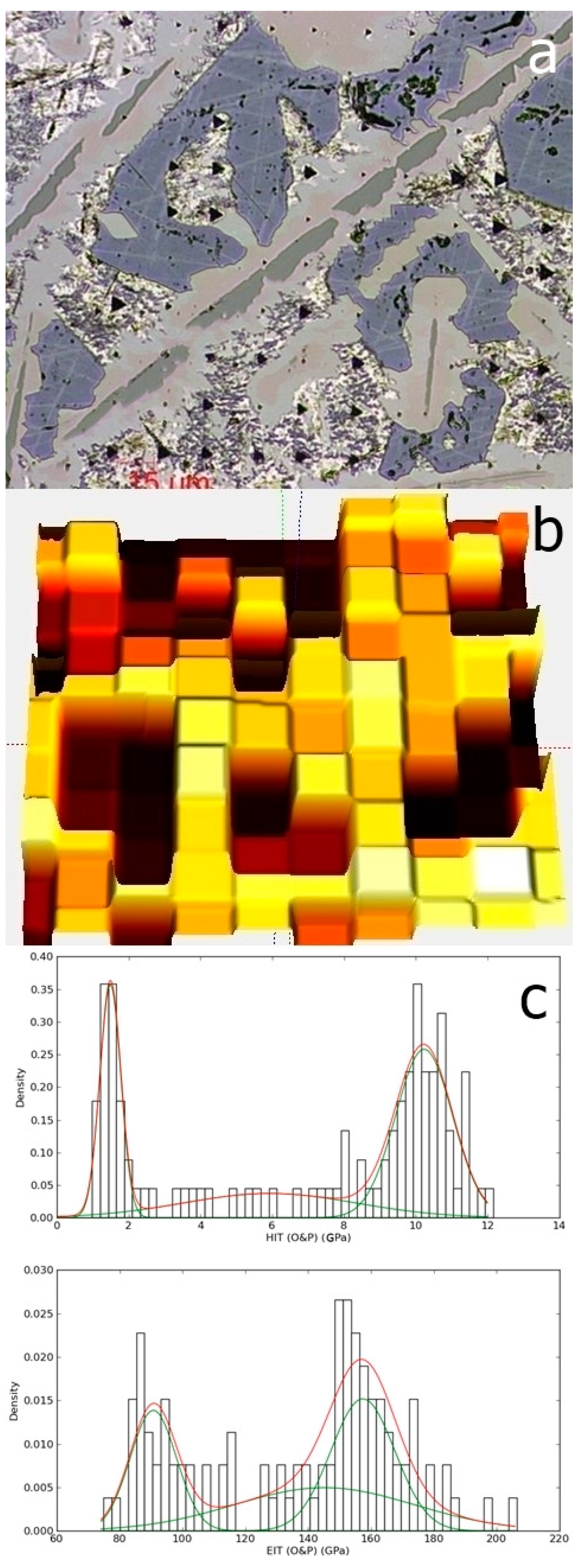
Metals 09 00483 g011
Figure 12. The indentation matrix (a) and the surface mapping as function of hardness (b); the hardness and elastic modulus distribution (c), extracted from the surface mapping, for the Al79Si11Ni10 alloy.
Metals 09 00483 g012
Figure 13. The indentation matrix (a) and the surface mapping as function of hardness (b); the hardness and elastic modulus distribution (c), extracted from the surface mapping, for the Al67Si18Ni15 alloy.
Metals 09 00483 g013
Table 1. Chemical composition of the Al–Si–Ni alloys.
AlloyChemical CompositionAlSiNiBulkMelt-SpunAtomized
Al79Si11Ni10(at. %)791110---
(wt. %)70.4110.219.39
Al67Si18Ni15(at. %)671815---
(wt. %)56.615.8327.57
Table 2. The surface chemical composition, obtained by energy dispersion spectroscopy system.
AlloyAcquisition SiteChemical Composition (at. %)
AlSiNi
Al79Si11Ni10 in bulk formspectrum 174.51-25.49
spectrum 280.8318.660.51
Al67Si18Ni15 in bulk formspectrum 148.9510.6940.36
spectrum 273.011.2625.73
spectrum 30.4299.100.48
Al79Si11Ni10 melt-spun ribbons, as castsum spectrum78.2312.928.85
Al79Si11Ni10 melt-spun ribbons, heat treatedsum spectrum77.6414.018.35
Al67Si18Ni15 melt-spun ribbons, as castsum spectrum64.7822.0413.18
Al67Si18Ni15 melt-spun ribbons, heat treatedsum spectrum76.0114.769.23
Table 3. Mechanical characteristics of the fast solidified Al79Si11Ni10 and Al67Si18Ni15 alloys.
MechanicalAl79Si11Ni10Al67Si18Ni15Al67Si18Ni15
PropertiesMelt SpunMelt SpunAtomized
H (GPa)4.74 ± 0.466.29 ± 0.274.13 ± 0.31
E (GPa)94.03 ± 6.7070.29 ± 1.0287.85 ± 4.55
H/E0.0500.0900.047
H3/E20.0120.0510.009

