Article

The Size Effect on Forming Quality of Ti–6Al–4V Solid Struts Fabricated via Laser Powder Bed Fusion

1
College of Mechanical and Electrical Engineering, Nanjing University of Aeronautics and Astronautics, Nanjing 210016, China
2
Suzhou Kangli Orthopedics Instrument Co. Ltd., Suzhou 215600, China
3
National Center of Supervision and Inspection on Additive Manufacturing Products Quality (JIANGSU), Wuxi 214028, China
4
Jiangsu Key Laboratory of 3D Printing Equipment and Manufacturing, Nanjing Normal University, Nanjing 210042, China
5
Department of Engineering and Design, University of Sussex, Sussex House, Brighton BN19RH, UK
*
Author to whom correspondence should be addressed.
Metals 2019, 9(4), 416; https://doi.org/10.3390/met9040416
Submission received: 4 March 2019 / Revised: 31 March 2019 / Accepted: 3 April 2019 / Published: 6 April 2019
(This article belongs to the Special Issue Additive Manufacturing of Metals)

Abstract

:
Laser powder bed fusion (LPBF) is useful for manufacturing complex structures; however, factors affecting the forming quality have not been clearly researched. This study aimed to clarify the influence of geometric characteristic size on the forming quality of solid struts. Ti–6Al–4V struts with a square section on the side length (0.4 to 1.4 mm) were fabricated with different scan speeds. Micro-computed tomography was used to detect the struts’ profile error and defect distribution. Scanning electron microscopy and light microscopy were used to characterize the samples’ microstructure. Nanoindentation tests were conducted to evaluate the mechanical properties. The experimental results illustrated that geometric characteristic size influenced the struts’ physical characteristics by affecting the cooling condition. This size effect became obvious when the geometric characteristic size and the scan speed were both relatively small. The solid struts with smaller geometric characteristic size had more obvious size error. When the geometric characteristic size was smaller than 1 mm, the nanohardness and elastic modulus increased with the increase in scan speed, and decreased with the decline of the geometric characteristic size. Therefore, a relatively high scan speed should be selected for LPBF—the manufacturing of a porous structure, whose struts have small geometric characteristic size.

1. Introduction

As a unique type of structural and functional material, a porous structure has unique advantages in fields including filtration and separation [1], energy absorption [2], heat exchange [3], electromagnetic shielding [4], and artificial implants [5], and is widely used in aerospace, automotive, chemical, and biological medical industries. Depending on the demand, the porous structure can be manufactured from materials including metal [6,7], ceramics [8], and polymers [9]. With the deepening of their application, porous structures with function-oriented design have been widely developed to obtain precise and complex structures, such as porous implants [10]. However, it is difficult to fabricate such structures using the traditional processing method. Additive manufacturing (AM) techniques are attracting increasing attention due to their impressive capability to produce precise parts with a controlled architecture [11]. Using a layer-wise building approach and a direct link with a computer-aided design (CAD) model, AM has been described as a crucial production technique to achieve a more controlled porous structure [12,13,14,15]. A recently developed AM technique, the laser powder bed fusion process (LPBF), usually called selective laser melting (SLM), can directly create a functional and complex metal part, like a Ti-based porous scaffold for bone tissue engineering, bringing a high degree of freedom to design [16,17]. Most researchers have focused on evaluating the function or forming quality of as-designed porous samples fabricated by LPBF using a set of universal process parameters embedded in the commercial equipment [6,18,19,20,21,22]. However, a porous structure is composed of the struts or walls, which usually have small geometric characteristic size, so a set of process parameters with a universal nature may not be optimal for manufacturing porous structures. A small number of researchers have focused on the impact of process parameters on the forming quality of LPBF-built porous structures. For example, Liu et al. [23] investigated the effect of the scan speed on the forming defects, precision, and mechanical properties of biomedical titanium alloy scaffolds fabricated by LPBF. Ahmadi et al. [24] studied the effects of laser power on features including the surface roughness, strut diameter, relative density, hardness, and elastic modulus of the porous structures. In addition, Jamshidinia and Kovacevic found that the thin wall achieved more heat accumulation during the LPBF process, affecting the forming quality [25]. These findings indicate that the small geometric characteristic size may be a factor affecting the forming quality of LPBF-built porous structures.
On the basis of the above statement, the effect of the geometric characteristic size of the objective part on the forming quality of the solid strut is discussed in this work. The energy density was introduced to reveal the combined action of scan speed, laser power, hatching space, and layer thickness [26], which represented the thermal input during the LPBF process. As the most commonly used material in metal implant fields, Ti–6Al–4V alloy powder was selected for the experiment. Taking the geometric characteristic size into consideration, the influence rule of the factor on the forming quality of solid struts fabricated via LPBF using different scan speeds was investigated from the perspective of thermal transmission. The entire experiment was made up of two steps. Firstly, struts with different geometric characteristic size were fabricated using different combined process parameters. Secondly, porous structures with two strut sizes were fabricated with two scan speeds to verify the analysis in the first step.

2. Materials and Methods

2.1. Materials

Commercial Ti–6Al–4V alloy powder supplied by EOS GmbH was used in the experiment, meeting ISO 5832-3 and ASTM F1472. As an optimized medical material, the trace elements of Ti–6Al–4V ELI such as O, N, H, C, and Fe are relatively low in content (Table 1). As shown in Figure 1 (SEM, ΣIGMA, Zeiss, German), the powder has high sphericity and few satellite spheres with a particle size range of 15–53 μm.

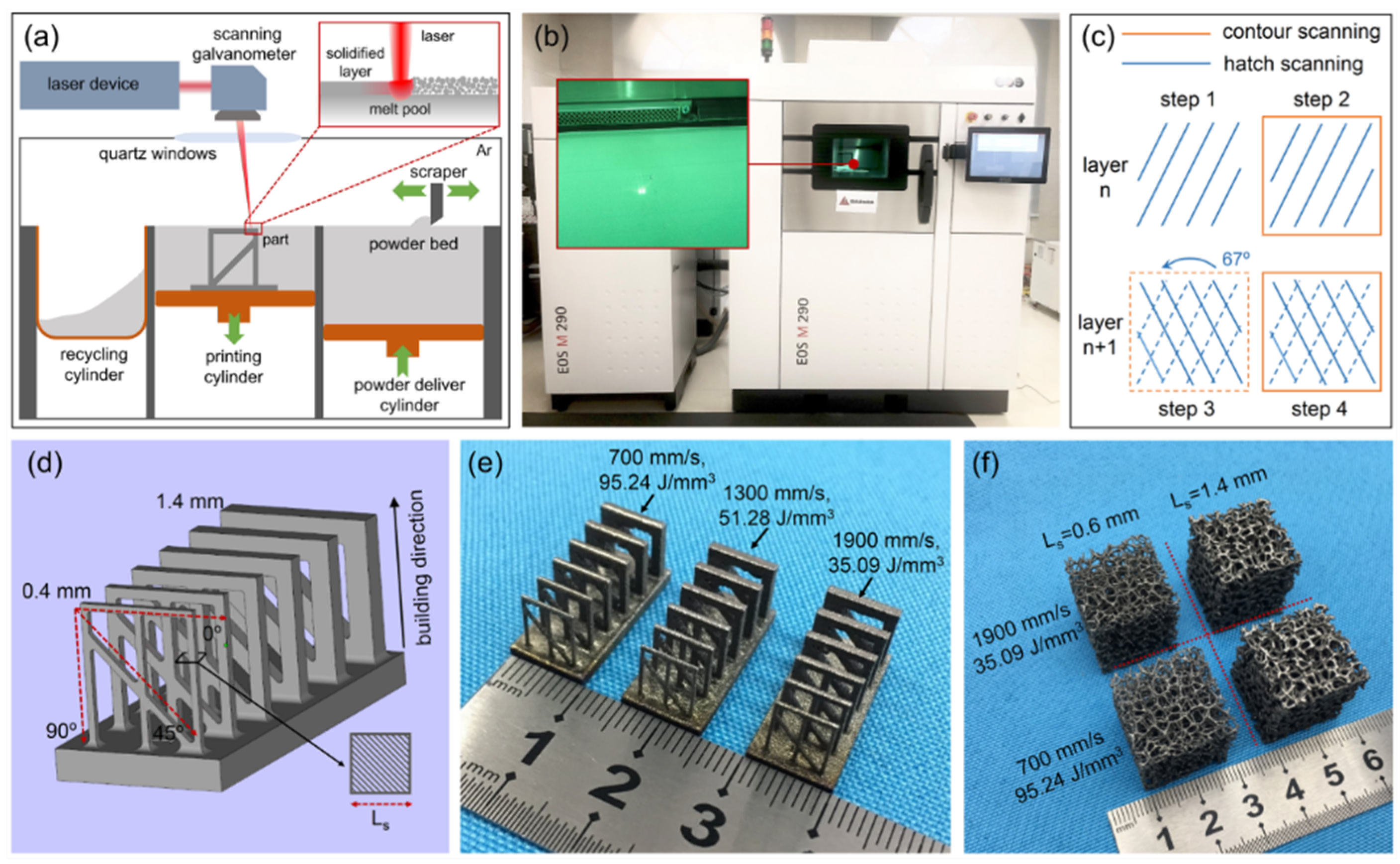
2.2. Design and Fabrication

Selective laser melting of a porous structure is characterized by a controllable and precise layer-wise material addition process. This method generates complex structures by selectively melting successive layers of metal powder using a focused and computer-controlled laser beam (Figure 2a). The specimens were fabricated using an LPBF machine (EOSINT M290; EOS GmbH, Munich, Germany), which was equipped with a Yb fiber laser of 400 W with a wavelength range of 1000–1100 nm and a Gaussian spot, and a building chamber filled with argon gas with an oxygen content below 200 ppm.
The volumetric energy density (Ev) was calculated according to Equation (1) [22]:
Ev = P/(v × h × d),
where P is the laser power, h is the hatching space, v is the scan speed, and d is the layer thickness. This equation takes the most important laser parameters into account and is suitable for calculating the thermal input during the LPBF process. An inside to outside scanning strategy with a meander hatch style was selected. The meander hatch direction rotated by an angle of 67° in the following layer (Figure 2c).
A porous structure is generally made up of struts with relatively small size and various angles. In this work, the sample model consisted of struts with angles of 0°, 45°, and 90°, which had a square section with a side length (Ls) of 0.4 to 1.4 mm (Figure 2d). Three sets of parameters were used in this fabrication process, resulting in different volumetric energy densities of 95.24, 51.28, and 35.09 J/mm3 (Table 2 and Figure 2e). To verify the correctness of the analysis, two kinds of porous structures with as-designed Ls values of 0.6 and 1.4 mm were fabricated via the LPBF process with v values of 700 and 1900 mm/s, respectively (Figure 2f).

2.3. Measurements and Characterizations

A micro-computed tomography (μCT) scanner (FF35 CT; YXLON International, Hamburg, Germany) with 5 μm resolution was used to scan the samples at 200 kV and 50 μA. The samples were rotated over 360° in steps of 0.18° during the acquisition. Two-dimensional (2D) projection images (n = 2000) were then collected. The 3D models of the fabricated samples were reconstructed through slice image data using commercially available software (VG Studio MAX 3.0; Volume Graphics GmbH, Heidelberg, Germany). The same software was also used to detect the size deviation distribution of the as-built samples compared to the 3D model with an error of 5 μm (n = 3). The sample section profile and defect distribution (pores) were then extracted from the CT data. After CT scanning, the struts with the same square were cut off together from the base plate via wire electrical discharge machining (WEDM). The relative density of struts with the same square section was measured using the Archimedes method on each set of samples. The Archimedes test results were calculated based on a combination of dry weighing and weighing in pure ethanol and on the theoretical density of 4.43 g/cm3 for Ti–6Al–4V. Taking open porosity and the highly developed surface of the samples into consideration, the samples were coated with wax after the first dry weighing. The relative density (ρrelative) of the samples was calculated using Equation (2):
ρrelative = m1/[(m2m3)/ρethanol − (m2m1)/ρwax],
where m1 is the mass of the sample without a wax coating in air, m2 is the mass of the sample with a wax coating in air, and m3 is the mass of the sample with a wax coating in pure ethanol. Due to the weight of the struts being too small, ten samples of each set were measured together, and the arithmetic mean value of relative density was calculated (n = 10). Taking the small size of the struts into consideration, nanoindentation tests on the polished sections of as-built struts with an angle of 90° were performed using a nanoindenter (G200, Agilent, Ltd., Santa Clara, CA, USA) to evaluate the mechanical properties, including the elastic modulus and nanohardness. A loading–unloading test mode was used with a maximum indentation depth of 2000 nm, a loading speed of 10 nm/s, and a hold time of 10 s (n = 5). The Oliver-Pharr method [27] was then applied to calculate the nanohardness and elastic modulus. The microstructure of LPBF-produced struts with an angle of 90° was observed using a field-emission scanning electron microscope (S-4800; Hitachi, Ltd., Tokyo, Japan) and a light microscope (GX41; Olympus, Ltd., Tokyo, Japan). To reveal the microstructure, an etchant containing 50 mL distilled water, 25 mL HNO3, and 5 mL HF was used for the polished samples. The difference in phase composition was analyzed by X-ray diffraction (XRD) using an X-ray diffractometer (D/max 2500 PC, Rigaku, Ltd., Tokyo, Japan) with Cu Kα radiation at 40 kV with a beam current of 100 mA. A scan speed of 2°/min was used for the scan range of 30–80° in steps of 0.02°. The porosity (Φ) of the fabricated porous structure was obtained from Equation (3):
Φ = 1 − Vporous/Vbulk,
where Vporous is the volume of the LPBF-produced structure measured from reconstructed 3D models using commercially available software (Magics 21.0.0; Materialise, Leuven, Belgium) and Vbulk is the total volume of the solid cube that has the same outline size as the porous sample (n = 3). The main information of all the measuring methods is presented in Table 3.

3. Results

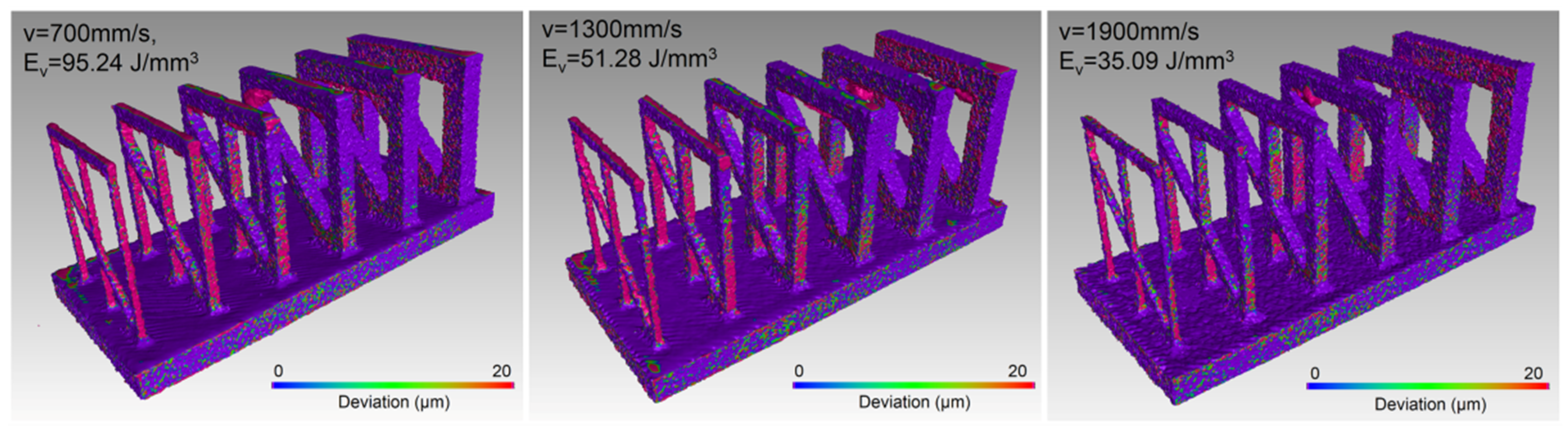
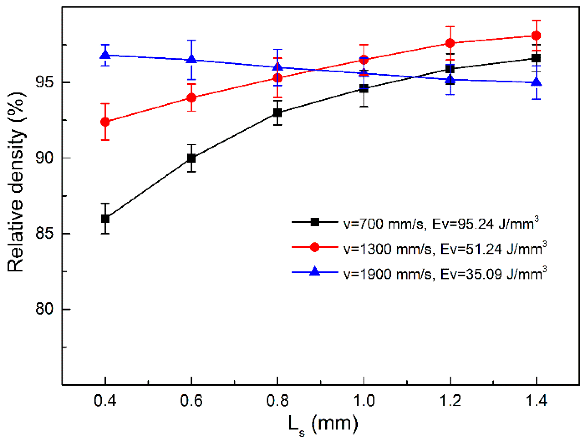
3.1. Morphology Features, Relative Density and Defects

The results of the geometric profile error comparison between the as-built samples and the as-designed 3D model are presented in Figure 3 and Table 4. As illustrated in Figure 3, the solid struts with small Ls (0.4, 0.6, 0.8 mm) more easily gained a positive error in size. The higher v made this phenomenon more obvious. The solid struts with larger Ls (>1 mm) had a more stable size. This was in agreement with the results shown in Table 4. Under different v values of 1900, 1300, and 700 mm/s, the struts with an Ls value of 0.4 mm had sizes of 412 ± 20, 465 ± 27, and 489 ± 34 μm, respectively, and the strut with an Ls value of 1.4 mm had sizes of 1432 ± 15, 1421 ± 23, and 1430 ± 51 μm, respectively. For the overhanging struts with an angle of 0°, the actual size was larger than that of the vertical struts. This was because the molten pool would usually generate many tumor forms on the bottom surface, owing to the permeation effect, causing an uneven geometric profile and over-dimension as a condition of low scan speed (Figure 5).
The relative density of the as-built samples is depicted in Figure 4. Under the process conditions of different scan speeds, the struts presented inconsistent variation trends with increasing geometric characteristic size. On one hand, for the struts with small Ls (0.4, 0.6, and 0.8 mm), the relative densities of the samples with a v of 1900 mm/s were highest, separately reaching 96.8%, 96.5%, and 96%. The relative density of samples with a v of 700 mm/s was lowest, only reaching 86%, 90%, and 93%. On the other hand, for the struts with an Ls value of 1.4 mm, the relative density of the samples with a v of 1300 mm/s was highest, reaching 98.1%, and the relative density of samples with a v of 1900 mm/s was lowest at 95%. Thus, it could be seen that the relative density was sensitive to not only scan speed but also to the geometric characteristic size.
In the thresholding CT images shown in Figure 5, the pore distribution of the as-built struts with different dimensions, angles, and scan speeds is roughly demonstrated. This result echoes the relative density, as described in Figure 4. It is apparent that the number of pores decreased with the increase in scan speed for the struts with an Ls value of 0.4 mm, and the struts with an angle of 45° or 0° tended to generate pores. However, the struts with an Ls value of 1.4 mm had the least pores in the condition of a v value of 1300 mm/s.

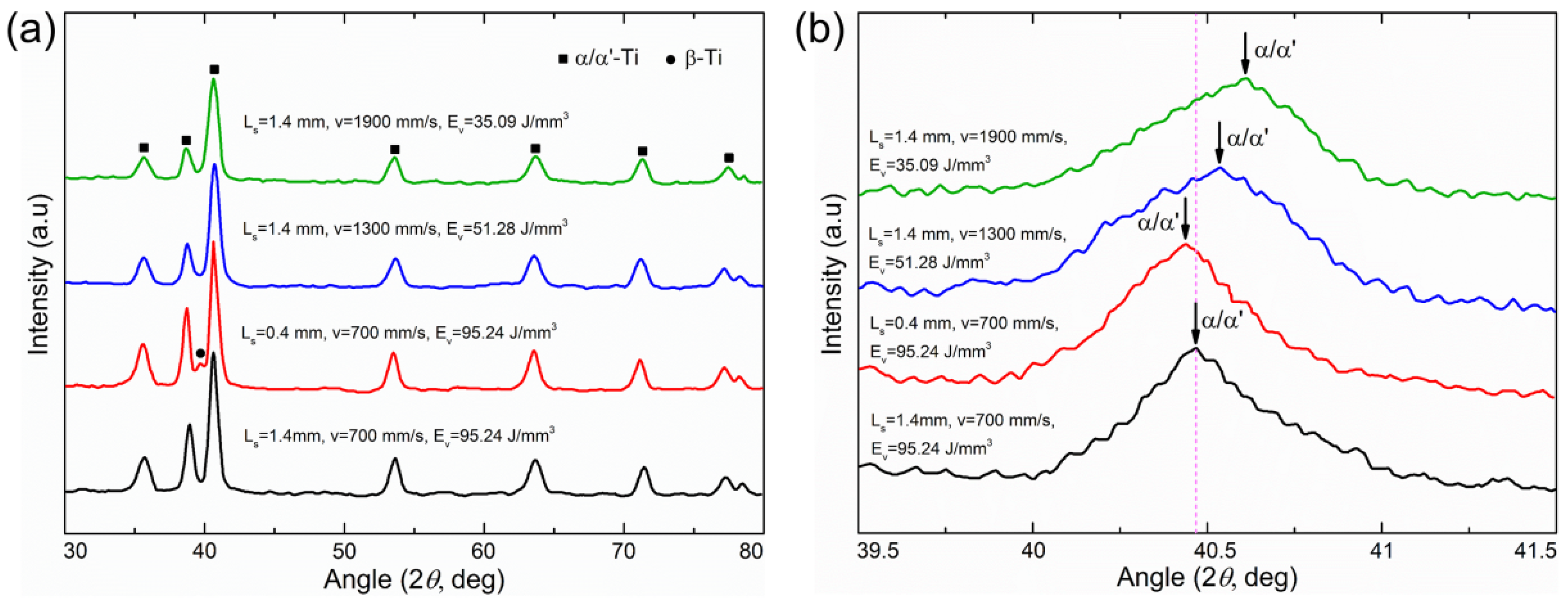
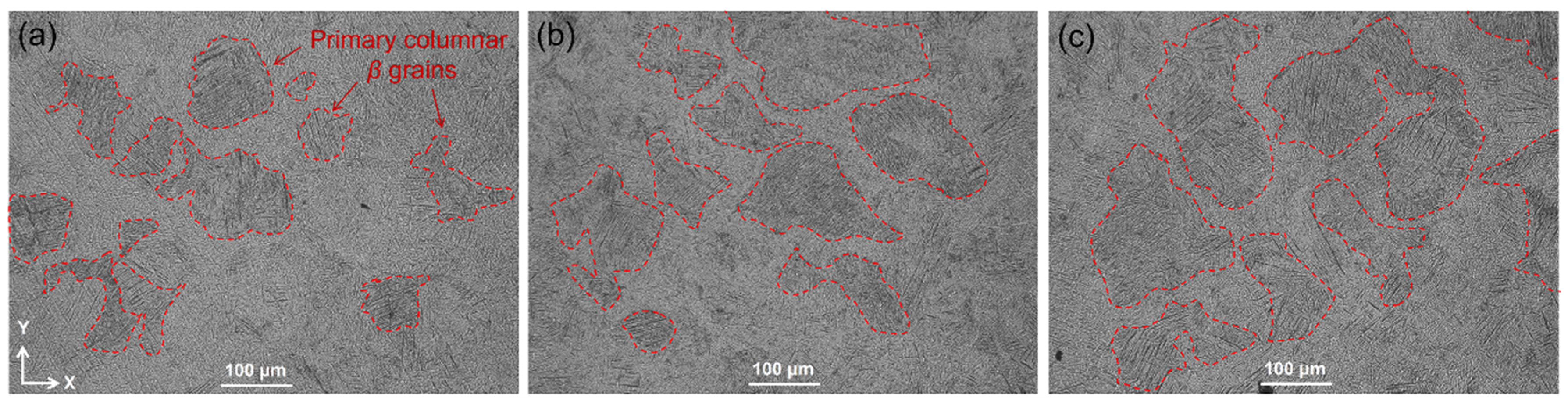
3.2. Phase Identification and Microstructure

Figure 6 shows the X-ray diffraction analysis performed to identify phases of the struts with Ls values of 0.4 and 1.4 mm under different process conditions. As shown in Figure 6a, a brief observation of four struts within a wide 2θ range of 30° to 80° revealed that the LPBF-built Ti–6Al–4V samples’ phase was mainly composed of α/α’ phase. It is known that all of these phases are α’ phases, due to the large cooling rate caused by laser melting and solidification [28]. For the struts with an Ls value of 1.4 mm, when the scan speed increased, the diffraction peaks broadened considerably and the intensity decreased, which implied the formation of considerable refined crystal [29]. The XRD characterization with a small 2θ range of 39.5° to 41.5° is depicted in Figure 6b. It shows that the refined 2θ locations of peaks of struts with an Ls value of 1.4 mm generally shifted to the higher 2θ with the increase in scan speed. In addition, under the process condition of a v of 700 mm/s, the peak of the strut with an Ls value of 0.4 mm became thinner than that of the strut with an Ls value of 1.4 mm. This means that the strut with an Ls value of 0.4 mm had a coarser microstructure than did the strut with an Ls value of 1.4 mm. The relatively small geometric characteristic size might have affected the heat dissipation of newly produced solid struts.
To further understand the microstructural differences, observation using an optical metallographic microscope and SEM was conducted on the initial microstructure of the X–Y planes perpendicular to the building direction, and the results are provided in Figure 7 and Figure 8. Figure 7 reveals that the section microstructure was composed of very fine acicular martensites α’ and primary columnar β grains with different shapes, which grew along the building direction. The interior of the primary columnar β grains mainly consisted of relatively coarse acicular martensites α’ throughout the entire grain. This result is consistent with the findings of the XRD analysis in Figure 6a. Due to the optical metallographic microscope having relatively low magnification and the generation of multilevel martensites α’ caused by the repetitive thermal loading of layer-wise laser melting, there was no obvious difference observed in the acicular martensites of struts with different process conditions. However, the primary columnar β grains became thicker and coarser with increasing scan speed. Moreover, as SEM images with 2000× magnification, shown in Figure 8, under the same condition of a v of 700 mm/s, the martensites α’ in the strut with an Ls value of 0.4 mm were obviously coarser than that of the struts with an Ls value of 1.4 mm, on the whole.

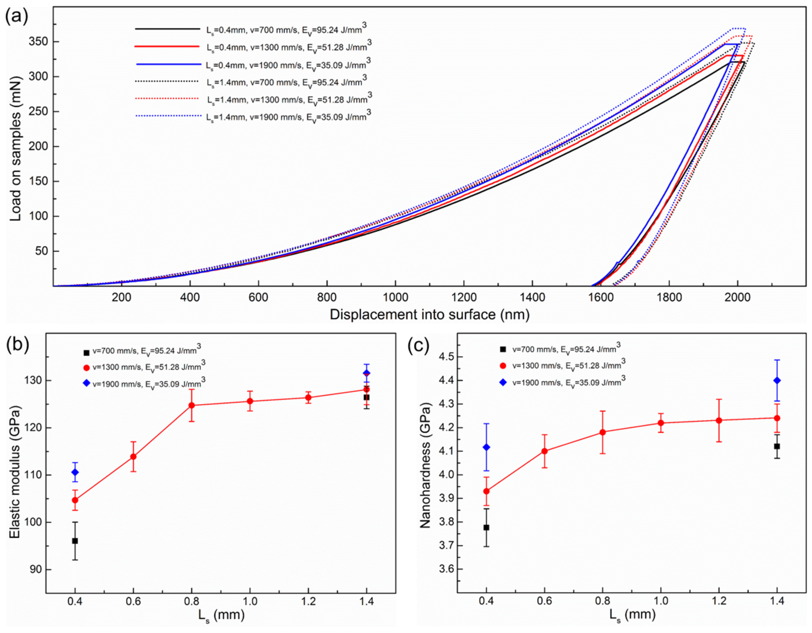
3.3. Mechanical Performance
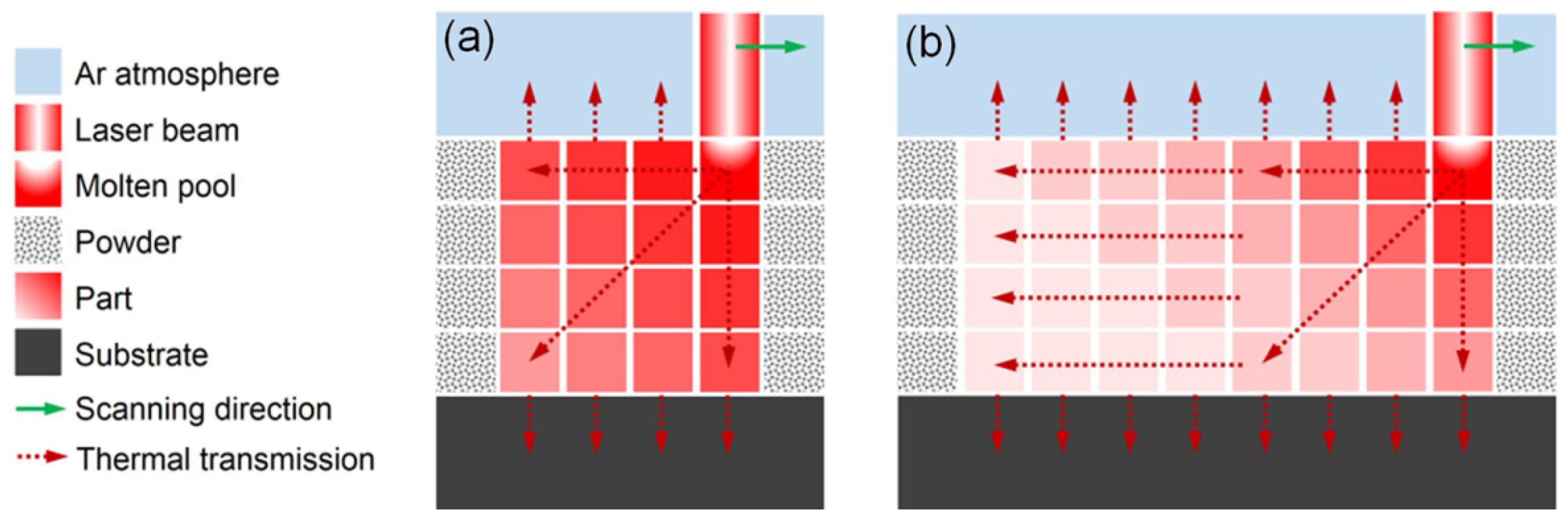
Figure 9a depicts the nanoindentation load–displacement curves measured on the polished sections of the as-built struts with an angle of 90° and Ls values of 0.4 and 1.4 mm. The indentation depths of the struts with an Ls value of 1.4 mm were larger than those of the struts with an Ls value of 0.4 mm after unloading. As shown in Figure 9b,c, for the struts with a v of 1300 mm/s, the nanohardness and elastic modulus increased with increasing geometric characteristic size. It is noteworthy that the nanohardness and elastic modulus increased very slightly and indistinctively after Ls reached 1 mm. For the struts with an Ls value of 0.4 mm, the nanohardness reached 3.78 to 4.12 GPa and the elastic modulus reached 96.044 to 110.613 GPa. For the struts with an Ls value of 1.4 mm, the nanohardness reached 4.12 to 4.4 GPa and the elastic modulus reached 126.42 to 131.57 GPa. Overall, they all decreased with increasing scan speed.

4. Discussion

The existing experimental results suggested that the geometric characteristic size within a certain range would affect the physical characteristics of an LPBF-fabricated porous structure, including the morphology features, relative density, microstructure, and mechanical properties. This phenomenon can be explained through the simplified thermal transmission model in a laser powder bed fusion process (Figure 10). As a classical additive manufacturing method using a powder bed, three main thermal transferring forms occur during the LPBF process: thermal conduction from molten pool to part, thermal conduction from part to substrate, and thermal radiation from part to atmosphere [30]. It is important to note that thermal conduction between the part and the powder is negligible because the thermal conductivity coefficient of the metal powder is much smaller than that of the metal part [31]. Therefore, the as-built part could be regarded as a thermal container. According to Equation (1), the energy density is inversely proportional to the scan speed. The energy density represents its thermal source strength and the geometric characteristic size in a certain range reflects its own thermal storage volume and thermal-sinking capability. These two aspects will influence the temperature distribution of the as-built part. Higher energy density means that the molten pool will receive more heat from the laser beam, resulting in higher peak temperature, longer keeping time, and decreased undercooling degree [28]. A geometric characteristic size that is too small means that the molten pool and as-built part have a poor cooling condition, and less thermal storage volume and interfacial area with atmosphere and substrate, which results in a lower cooling rate. However, the phenomenon may gradually emerge when the geometric characteristic size is small enough (<1 mm).
As shown in Figure 10, a higher energy density means that the molten pool has less surface tension and better wettability, absorbing more powder. Due to the layer-wise manufacturing method, the side surface generally bonds a large quantity of incompletely melted particles, which may need post treatment for further applications. Based on the above analysis, a geometric characteristic size that is too small may more easily cause the as-built part to gain more obvious size errors under the high-scan-speed conditions. This is because the newly forming part will remain at a high temperature for a longer time under the poor cooling condition. Then, the side wall of the part will bond more particles, resulting in an obvious size error. The relative density of the LPBF-built part is associated with pore deficiency. Too high a temperature of the molten pool with too high energy density will cause the evaporation of elements, generating pores with rounded shapes. Too high a cooling rate of the molten pool with too low an energy density will cause the incomplete fusion of powder, also generating pores with sharp shapes and incompletely melted particles. In addition, the poor cooling condition relating to too small a geometric characteristic size will aggravate pore generation under the condition of high energy density.
It is known that for metal materials, hardness is closely related to the microstructure. There is also a loose corresponding relationship between hardness and strength, namely, high hardness corresponding to high strength. High hardness is attributed to the refinement of the α/α’ phase and β phase caused by rapid solidification, and much dislocation generation caused by residual stress in additive-manufactured Ti–6Al–4V parts [32]. The elastic modulus is associated with the residual stress level to a certain extent [33]. Based on the proposed thermal model, the higher energy density and small geometric characteristic size cause more thermal input and a poor cooling condition, respectively. This will weaken the grain refinement strengthening effect and decrease the residual stress, causing a decline in hardness and strength. A relatively low scan speed and small geometric characteristic size correspond to a low elastic modulus, which is partially due to the decrease of the residual stress [32].
As is known, the relative density is associated with the pore deficiency, and the porosity is associated with the size of the as-built struts of a porous structure. As shown in Figure 11, different from the porous structure with an Ls value of 1.4 mm, the relative density and porosity of the porous structures with an Ls value of 0.6 mm and a v of 700 mm/s were obviously less than those for the structures with a v of 1900 mm/s. This finding indirectly indicated that the struts of the porous sample with an Ls value of 1.4 mm achieved more pores and larger positive size error under the v of 700 mm/s. In other words, a porous structure with an Ls value of 0.6 mm and a v of 1900 mm/s had a better forming quality than did those with a v of 700 mm/s. These experimental results are in accordance with the results shown in Figure 3 and Figure 4, confirming the validity of the above analysis to a certain extent.

5. Conclusions

In this study, taking the geometric characteristic size into consideration, samples consisting of solid struts with different section characteristic sizes (0.4 to 1.4 mm) were fabricated by selective laser melting with three scan speeds (700, 1300, and 1900 mm/s). The morphology features, relative density, microstructure, and mechanical properties were measured and a simple thermal model was presented to systematically explain the effect of geometric characteristic size under different scan speed conditions. The following was determined:
(1) The geometric characteristic size influenced the physical characteristics of the LPBF-produced struts by affecting the cooling condition. A small geometric characteristic size resulted in a poor cooling condition. The effect may only become obvious when the geometric characteristic size is small (<1 mm).
(2) The relative density of the solid strut with an Ls value of 0.4 mm reached the highest value of 96.8% when the v was 1900 mm/s, but the relative density of the solid strut with an Ls value of 1.4 mm reached the highest value of 98.1% when the v was 1300 mm/s. The solid strut with smaller geometric characteristic size had a more obvious size error. To a certain degree, the nanohardness and elastic modulus increased with increasing scan speed, and decreased with the decline of the geometric characteristic size when the geometric characteristic size was smaller than 1 mm.
(3) In contrast to the solid bulk forming process, for a superior forming quality, a higher scan speed should be set for the LPBF-manufacturing of porous structures, especially for structures with small geometric characteristic size in solid struts.

Author Contributions

Experiment design and writing, H.L. and D.X.; data analysis of μCT, Y.M.; data analysis of microstructure and nanoindentation, J.S. and C.W.; writing—review and editing, L.S. and Z.T.

Funding

This research was funded by the Advanced Research Project of Army Equipment Development (301020803), the Key Research and Development Program of Jiangsu (BE 2015161), the Young Scientists Fund of the National Natural Science Foundation of China (51605473), the Jiangsu Provincial Research Foundation for Basic Research, China (BK 20161476), the Science and Technology Planning Project of Jiangsu Province of China (BE 2015029) and the Science and Technology Support Program of Jiangsu (BE 2014009-1, BE 2014009-2, BE 2016010-3).

Conflicts of Interest

The authors declare no conflicts of interest.

References

  1. Jena, A.; Gupta, K. Characterization of pore structure of filtration media. Fluid Part. Sep. J. 2002, 14, 227–241. [Google Scholar]
  2. Chen, D.; Kitipornchai, S.; Yang, J. Dynamic response and energy absorption of functionally graded porous structures. Mater. Des. 2018, 140, 473–487. [Google Scholar] [CrossRef]
  3. Hutter, C.; Büchi, D.; Zuber, V.; Rudolf von Rohr, P. Heat transfer in metal foams and designed porous media. Chem. Eng. Sci. 2011, 66, 3806–3814. [Google Scholar] [CrossRef]
  4. Xu, Z.; Hao, H. Electromagnetic interference shielding effectiveness of aluminum foams with different porosity. J. Alloys Compd. 2014, 617, 207–213. [Google Scholar] [CrossRef]
  5. Krishna, B.V.; Bose, S.; Bandyopadhyay, A. Low stiffness porous Ti structures for load-bearing implants. Acta Biomater. 2007, 3, 997–1006. [Google Scholar] [CrossRef] [PubMed]
  6. Liang, H.; Yang, Y.; Xie, D.; Li, L.; Mao, N.; Wang, C.; Tian, Z.; Jiang, Q.; Shen, L. Trabecular-like Ti-6Al-4V scaffolds for orthopedic: Fabrication by selective laser melting and in vitro biocompatibility. J. Mater. Sci. Technol. 2019. [Google Scholar] [CrossRef]
  7. Gao, C.; Wu, P.; Yang, Y.; Feng, P.; Shuai, C.; He, C.; Bin, S.; Guo, W. Biodegradation mechanisms of selective laser-melted Mg–x Al–Zn alloy: Grain size and intermetallic phase. Virtual Phys. Prototyp. 2017, 13, 59–69. [Google Scholar]
  8. Ohji, T.; Fukushima, M. Macro-porous ceramics: Processing and properties. Int. Mater. Rev. 2012, 57, 115–131. [Google Scholar] [CrossRef]
  9. Dhandayuthapani, B.; Yoshida, Y.; Maekawa, T.; Kumar, D.S. Polymeric Scaffolds in Tissue Engineering Application: A Review. Int. J. Polym. Sci. 2011, 2011, 1–19. [Google Scholar] [CrossRef]
  10. Wang, X.; Xu, S.; Zhou, S.; Xu, W.; Leary, M.; Choong, P.; Qian, M.; Brandt, M.; Xie, Y.M. Topological design and additive manufacturing of porous metals for bone scaffolds and orthopaedic implants: A review. Biomaterials 2016, 83, 127–141. [Google Scholar] [CrossRef] [PubMed]
  11. Leong, K.F.; Cheah, C.M.; Chua, C.K. Solid freeform fabrication of three-dimensional scaffolds for engineering replacement tissues and organs. Biomaterials 2003, 24, 2363–2378. [Google Scholar] [CrossRef]
  12. Parthasarathy, J.; Starly, B.; Raman, S. A design for the additive manufacture of functionally graded porous structures with tailored mechanical properties for biomedical applications. J. Manuf. Process. 2011, 13, 160–170. [Google Scholar] [CrossRef]
  13. Dinda, G.P.; Song, L.; Mazumder, J. Fabrication of Ti-6Al-4V scaffolds by direct metal deposition. Metall. Mater. Trans. A Phys. Metall. Mater. Sci. 2008, 12, 2914–2922. [Google Scholar] [CrossRef]
  14. Ponader, S.; Von Wilmowsky, C.; Widenmayer, M.; Lutz, R.; Heinl, P.; Körner, C.; Singer, R.F.; Nkenke, E.; Neukam, F.W.; Schlegel, K.A. In vivo performance of selective electron beam-melted Ti-6Al-4V structures. J. Biomed. Mater. Res. Part A 2010, 92, 56–62. [Google Scholar] [CrossRef]
  15. Salmi, M.; Tuomi, J.; Paloheimo, K.; Paloheimo, M.; Björkstrand, R.; Mäkitie, A.A.; Mesimäki, K.; Kontio, R. Digital design and rapid manufacturing in orbital wall reconstruction. In Innovative Developments in Design and Manufacturing, 1st ed.; Reddy, J.N., Ed.; CRC Press: London, UK, 2009; pp. 357–360. [Google Scholar]
  16. Kruth, J.P.; Levy, G.; Klocke, F.; Childs, T.H.C. Consolidation phenomena in laser and powder-bed based layered manufacturing. CIRP Ann. Manuf. Technol. 2007, 56, 730–759. [Google Scholar] [CrossRef]
  17. Warnke, P.H.; Douglas, T.; Wollny, P.; Sherry, E.; Steiner, M.; Galonska, S.; Becker, S.T.; Springer, I.N.; Wiltfang, J.; Sivananthan, S. Rapid Prototyping: Porous Titanium Alloy Scaffolds Produced by Selective Laser Melting for Bone Tissue Engineering. Tissue Eng. Part C Methods 2009, 15, 115–124. [Google Scholar] [CrossRef] [PubMed]
  18. Yan, C.; Hao, L.; Hussein, A.; Raymont, D. Evaluations of cellular lattice structures manufactured using selective laser melting. Int. J. Mach. Tools Manuf. 2012, 62, 32–38. [Google Scholar] [CrossRef]
  19. Van Bael, S.; Kerckhofs, G.; Moesen, M.; Pyka, G.; Schrooten, J.; Kruth, J.P. Micro-CT-based improvement of geometrical and mechanical controllability of selective laser melted Ti6Al4V porous structures. Mater. Sci. Eng. A 2011, 528, 7423–7431. [Google Scholar] [CrossRef]
  20. Shirazi, S.F.S.; Gharehkhani, S.; Mehrali, M.; Yarmand, H.; Metselaar, H.S.C.; Adib Kadri, N.; Osman, N.A.A. A review on powder-based additive manufacturing for tissue engineering: Selective laser sintering and inkjet 3D printing. Sci. Technol. Adv. Mater. 2015, 16, 1–20. [Google Scholar] [CrossRef] [PubMed]
  21. Weißmann, V.; Bader, R.; Hansmann, H.; Laufer, N. Influence of the structural orientation on the mechanical properties of selective laser melted Ti6Al4V open-porous scaffolds. Mater. Des. 2016, 95, 188–197. [Google Scholar] [CrossRef]
  22. Wauthle, R.; Vrancken, B.; Beynaerts, B.; Jorissen, K.; Schrooten, J.; Kruth, J.; Humbeeck, J. Van Effects of build orientation and heat treatment on the microstructure and mechanical properties of selective laser melted Ti6Al4V lattice structures. Addit. Manuf. 2015, 5, 77–84. [Google Scholar] [CrossRef]
  23. Liu, Y.J.; Li, X.P.; Zhang, L.C.; Sercombe, T.B. Processing and properties of topologically optimised biomedical Ti-24Nb-4Zr-8Sn scaffolds manufactured by selective laser melting. Mater. Sci. Eng. A 2015, 642, 268–278. [Google Scholar] [CrossRef]
  24. Ahmadi, S.M.; Hedayati, R.; Ashok Kumar Jain, R.K.; Li, Y.; Leeflang, S.; Zadpoor, A.A. Effects of laser processing parameters on the mechanical properties, topology, and microstructure of additively manufactured porous metallic biomaterials: A vector-based approach. Mater. Des. 2017, 134, 234–243. [Google Scholar] [CrossRef]
  25. Jamshidinia, M.; Kovacevic, R. The influence of heat accumulation on the surface roughness in powder-bed additive manufacturing. Surf. Topogr. Metrol. Prop. 2015, 3, 1–10. [Google Scholar] [CrossRef]
  26. Simchi, A.; Pohl, H. Effects of laser sintering processing parameters on the microstructure and densification of iron powder. Mater. Sci. Eng. A 2003, 359, 119–128. [Google Scholar] [CrossRef]
  27. Oliver, W.C. An improved technique for determining hardness and elastic modulus using load displacement sensing indentation experiments. J. Mater. Res. 1992, 7, 1564–1583. [Google Scholar] [CrossRef]
  28. Thijs, L.; Verhaeghe, F.; Craeghs, T.; Van Humbeeck, J.; Kruth, J.P. A study of the microstructural evolution during selective laser melting of Ti-6Al-4V. Acta Mater. 2010, 58, 3303–3312. [Google Scholar] [CrossRef]
  29. Gu, D.; Hagedorn, Y.C.; Meiners, W.; Meng, G.; Batista, R.J.S.; Wissenbach, K.; Poprawe, R. Densification behavior, microstructure evolution, and wear performance of selective laser melting processed commercially pure titanium. Acta Mater. 2012, 60, 3849–3860. [Google Scholar] [CrossRef]
  30. Chiumenti, M.; Neiva, E.; Salsi, E.; Cervera, M.; Badia, S.; Moya, J.; Chen, Z.; Lee, C.; Davies, C. Numerical modelling and experimental validation in Selective Laser Melting. Addit. Manuf. 2017, 18, 171–185. [Google Scholar] [CrossRef]
  31. Abdul Aziz, M.S.; Furumoto, T.; Tanaka, R.; Hosokawa, A.; Alkahari, M.R.; Ueda, T. Thermal Conductivity of Metal Powder and Consolidated Material Fabricated via Selective Laser Melting. Key Eng. Mater. 2012, 523–524, 244–249. [Google Scholar]
  32. Song, L.; Xiao, H.; Ye, J.; Li, S. Direct laser cladding of layer-band-free ultrafine Ti6Al4V alloy. Surf. Coat. Technol. 2016, 307, 761–771. [Google Scholar] [CrossRef]
  33. Sun, G.; Zhou, R.; Lu, J.; Mazumder, J. Evaluation of defect density, microstructure, residual stress, elastic modulus, hardness and strength of laser-deposited AISI 4340 steel. Acta Mater. 2015, 84, 172–189. [Google Scholar] [CrossRef]
Figure 1. (a) SEM micrograph and (b) particle size distribution of Ti–6Al–4V powder.
Metals 09 00416 g001
Figure 2. (a) Schematic of the laser powder bed fusion process; (b) the LPBF machine of EOS M290; (c) the selected scanning strategy; (d) the as-designed 3D model of solid struts; (e) the as-built Ti–6Al–4V solid struts; and (f) the as-built Ti–6Al–4V porous structures for the confirmatory experiment.
Metals 09 00416 g002
Figure 3. Size deviation distribution of the as-built samples compared to the as-designed 3D model.
Metals 09 00416 g003
Figure 4. Arithmetic mean value of relative density of struts with different Ls and v values.
Metals 09 00416 g004
Figure 5. Thresholding single projection CT images of struts with Ls values of 0.4 and 1.4 mm.
Metals 09 00416 g005
Figure 6. X-ray diffraction analysis results of as-built samples: (a) diffraction angle 2θ of 30°–80°; (b) diffraction angle 2θ of 39.5° to 41.5°.
Metals 09 00416 g006
Figure 7. Optical images of microstructures of solid struts on the X–Y plane: (a) v = 1900 mm/s, Ls = 1.4 mm; (b) v = 1300 mm/s, Ls = 1.4 mm; and (c) v = 700 mm/s, Ls = 1.4 mm.
Metals 09 00416 g007
Figure 8. SEM images of the solid struts microstructure of martensites α’ on the X–Y plane: (a) v = 700 mm/s, Ls = 1.4 mm; (b) v = 700 mm/s, Ls = 0.4 mm.
Metals 09 00416 g008
Figure 9. (a) Loading–unloading curves; (b,c) the calculated elastic modulus and nanohardness from the nanoindentation tests.
Metals 09 00416 g009
Figure 10. Diagram of the thermal transmission model in the selective laser melting process. (a) Small geometric characteristic size; (b) large geometric characteristic size.
Metals 09 00416 g010
Figure 11. A comparison of the relative density and porosity for samples in the verification experiment.
Metals 09 00416 g011
Table 1. Chemical composition of Ti–6Al–4V powder (wt. %).
TiAlVONCHFe
Bal.5.903.910.120.050.080.0120.3
Table 2. The selected process parameters for LPBF-fabrication.
Laser Powder/P (W)Scan Speed/v (mm/s)Hatch Spacing/h (mm)Layer Thickness/d (mm)Laser Spot Diameter/D (mm)
200700, 1300, 19000.10.030.1
Table 3. Measuring objectives and methods in this study.
ObjectiveMethodApparatus
Size deviation and defect distributionμCTYXLON-FF35 CT, 200 Kv-50 μA, VG Studio MAX 3.0
Relative densityArchimedes methodSOPTOP-FA2004, ρwax = 0.9 g/cm3, ρethanol = 0.79 g/cm3
Porosity of porous structureΦ = 1 − (Vporous/Vbulk)Materialise-Magics 21.0.0
Mechanical propertiesNanoindentation testAgilent-G200, d = 2000 nm, v = 10 nm/s, t = 10 s
Phase identificationXRDRigaku-D/max 2500 PC, Cu, 40 kV, 100 mA
Microstructure observationsSEM and LMS-4800-Hitachi, Olympus-GX41
Table 4. The average values of measured sizes of the solid struts with Ls values of 0.4 and 1.4 mm (unit: μm, n = 10).
No.Ls (mm)v (mm/s)Measuring Place
70013001900
10.4489 ± 34465 ± 27412 ± 20 Metals 09 00416 i001
1.41430 ± 511421 ± 231432 ± 15
20.4543 ± 43507 ± 32498 ± 26
1.41427 ± 651412 ± 411437 ± 38
30.4705 ± 62654 ± 54642 ± 31
1.41598 ± 761553 ± 561543 ± 49

