Article

Experiment of Process Strategy of Selective Laser Melting Forming Metal Nonhorizontal Overhanging Structure

School of Materials Science and Mechanical Engineering, Beijing Technology and Business University, Beijing 100048, China
*
Author to whom correspondence should be addressed.
Metals 2019, 9(4), 385; https://doi.org/10.3390/met9040385
Submission received: 9 March 2019 / Revised: 23 March 2019 / Accepted: 25 March 2019 / Published: 27 March 2019
(This article belongs to the Special Issue Additive Manufacturing of Metals)

Abstract

:
To improve the precision of the nonhorizontal suspension structure and the forming quality of the overhanging surface by selective laser melting, the influence of laser power on the upper surface and the overhanging surface forming quality of 316L stainless steel at different forming angles was studied in the experiment. The influence of different scanning strategies, upper surface remelting optimization, and overhang boundary scanning optimization on the formation of overhanging structures was compared and analyzed. The forming effect of chromium–nickel alloy is better than 316L stainless steel below the limit forming angle in the overhanging structure. The better forming effect of chromium–nickel alloy can be obtained by narrowing the hatch space with the boundary optimization process. The experiment results show that the forming of the overhanging structure below the limit forming angle should adopt the chessboard scanning strategy. The smaller laser power remelting is beneficial to both the forming of the overhanging surface and the quality of upper surface forming. The minimum value of surface roughness using the 110 W power laser twice during surface remelting and boundary scanning 75° overhanging surface can reach 11.9 μm and 31.1 μm, respectively. The forming accuracy error range above the limit forming angle is controlled within 0.4 mm, and the forming quality is better. A boundary count scanning strategy was applied to this study to obtain lower overhanging surface roughness values. This research proposes a process optimization and improvement method for the nonhorizontal suspension structure formed by selective laser melting, which provides the process support for practical application.

Graphical Abstract

1. Introduction

As a rapid prototyping (RP) technique, selective laser melting (SLM) is a new technology and widely used in aerospace, automobile manufacturing, medical applications, industrial product design, architectural design, entertainment products, biotechnology, and other industrial fields [1,2]. SLM is an additive manufacturing technology and the principle is the discrete stacking which uses the high-energy laser beam to melt metal powder. The parts can be quickly formed without tools, fixtures, and molds with the advantages of short production cycle and high material utilization rate by using SLM [3,4,5].
Nonhorizontal suspension structure is the most basic and common structure encountered in the forming process, and is also the biggest geometric problem of forming in SLM experiments. Due to the inherent defects such as warpage, suspension, and sticky powder during processing, SLM cannot form parts with high quality and high precision. Therefore, if SLM can form overhanging structures with good quality, the technology will be improved and even promote the large-scale popularization and application of SLM. The support of forming is necessary and ensures the stability of the structure during the forming of suspension structures. At the same time, the excess heat will be transmitted by the support to prevent the structure from warping and deforming. However, the additional support will increase the time of processing, so it is necessary to investigate the strategy of forming suspension structures without support.
Kruth et al. [6] found that the forming level or near-level hanging surface can only be accurately formed by adding support. He [6,7] also proposed that adding monitoring and feedback devices in the optical system can flexibly change the laser power and improve the forming quality of the hanging surface. Yasa et al. [8] increased the feedback control of the forming process, laser surface remelting, laser etching, and other postprocessing methods to improve the forming effect of the suspension structure. From the microlevel view, the forming layer of the underside overhanging surface is a powder rather than metal entity, resulting in heat conduction, micromelting, adhesion, and other behaviors which are different from the solid structure. The behavior change of the molten pool can directly reflect the basic principle of SLM forming on the hanging surface. Therefore, many experts devote themselves to the forming mechanism of the microlevel suspension structure, and have obtained many achievements. Lott et al. [9] preliminarily expounded the dynamic behavior of the molten pool. Khan et al. [10] numerically simulated the molten pool instability in SLM forming, and concluded that the area of molten pool depended on the boundary conditions. Alkahari et al. [11] studied the molten pool behavior in the first-layer forming process under different laser powers, scanning speeds, and layer thicknesses by single-layer scanning experience.
The metal powder undergoes rapid melting, rapid cooling, and solidification during the SLM forming process due to the laser directly acting on the surface of the metal powder. The defects such as spheroidization, pores, cracks, dross, over-burning, warping, and so on are also the result of the varying of fast heat and rapid cooling. Some postprocessing methods (such as heat treatment, sanding, etc.) can improve the surface quality of the formed parts, but they are time-consuming and laborious and have limited effect, and for some complex structures (such as overhanging structures, hollow porous structures, etc.), it cannot be fundamentally solved by postprocessing methods. To eliminate the defect, it is necessary to decrease or even avoid the defect by adjusting the process parameters and other prior processes. Therefore, when forming parts such as a suspended structure or a complicated curved surface, a good forming effect should be obtained from the aspects of process parameters, scanning strategy, support added or not, and so on. In this study, the energy of the laser input was strictly controlled, and the process parameters, scanning strategy, support addition method, and auxiliary optimization process were changed. At the same time, the substrate was preheated by 100 °C to reduce the influence of temperature difference on the forming, and the optimal suspension structure was obtained with a good surface quality and high precision.

2. Materials and Methods

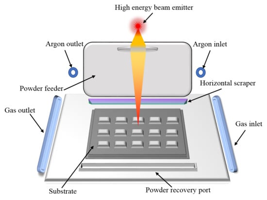
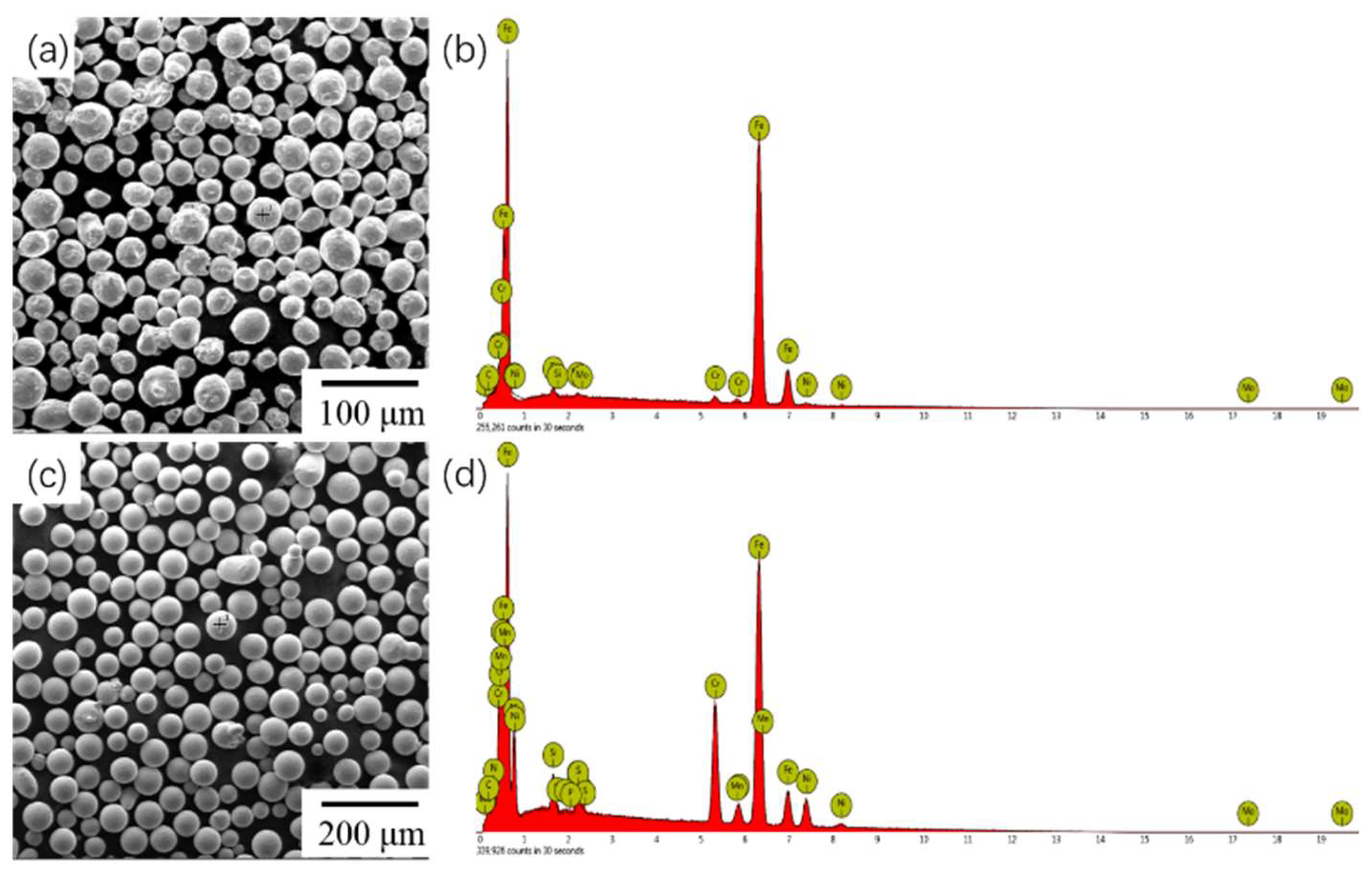
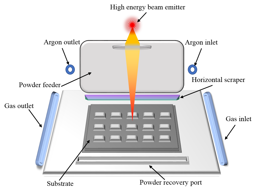
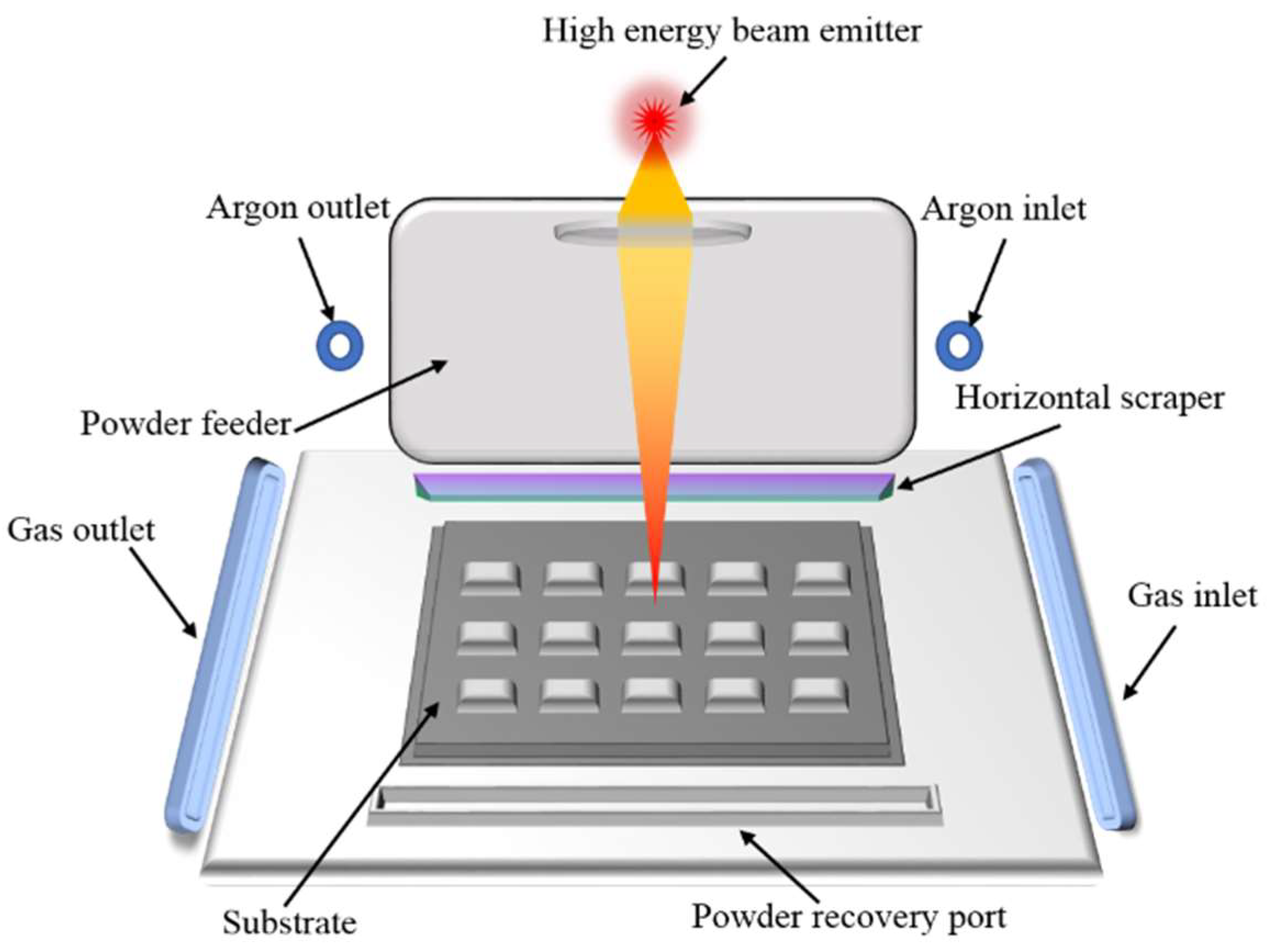
2.1. Materials and Experimental Setup

The experiment was carried out on the Renishaw AM400 (Renishaw plc, London, UK). The AM400 uses a continuous laser mode with a maximum power of 400 W and a 1075 nm Nd: YAG laser with a laser beam diameter of 70 μm. The working area (shown in Figure 1) can be machined to a maximum volume of 250 mm × 250 mm × 300 mm and provides a closed environment filled with argon as a shielding gas to maintain oxygen concentrations below 200 ppm. The experimental scanning strategy is based on the meander scan strategy, a schematic of which is shown in Figure 2; it can be seen that the angle between the Nth layer and the N+1th layer is 67°,where d is the point distance, δ is the hatch space, and Φ is the spot diameter.
There were two materials used in the experiment: one was the 316L stainless steel and the other was the chrome–nickel alloy steel. The 316L stainless steel had a particle diameter ranging from 5 μm to 41 μm and the average particle diameter was 17 μm. The chemical composition of the 316L stainless steel powder was Fe (Balance), Cr (16% to 18%), Ni (10% to 14%), Mo (2% to 3%), Mn (2% max), Si (1% max), N (0.1% max), O (0.1% max), P (0.045% max), C (0.03% max), S (0.03% max). The chrome–nickel alloy steel powder had an extremely high sphericity and a particle diameter ranging from 17 μm to 58 μm, and the average particle diameter was 31 μm. The chromium–nickel alloy steel included Fe (Balance), Cr (1% max), Mn (1% max), Ni (1% max), Mo (0.15% max), C (0.228% max), N (0.228% max). Electron microscopy (SEM) photographs and compositional contents are shown in Figure 3.

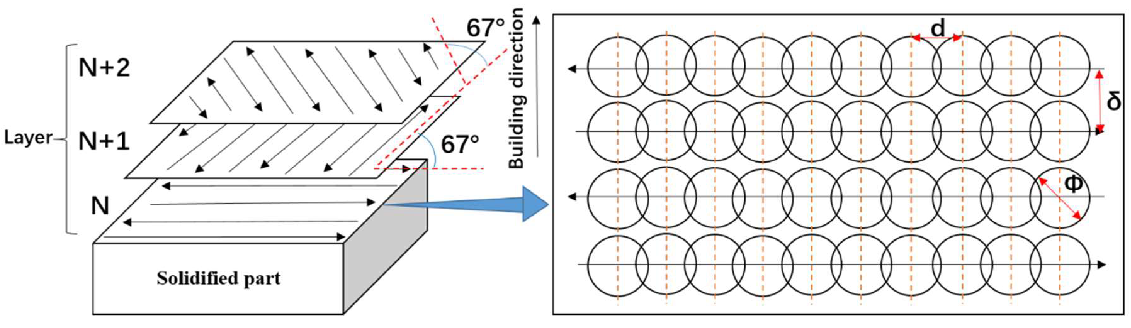
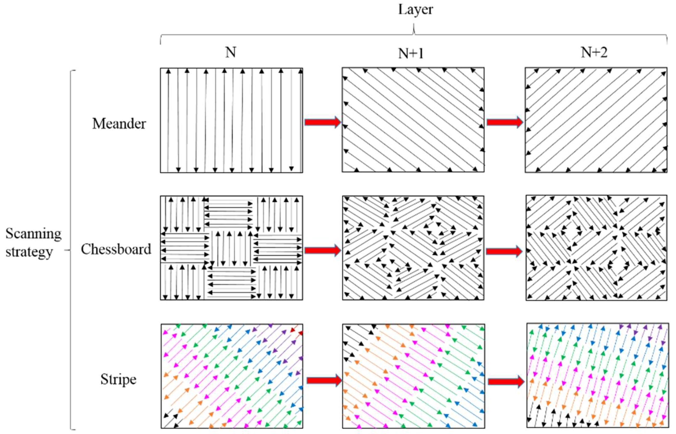
2.2. Forming Experiment

Firstly, 316L stainless steel powder was used for 50 μm layer thickness experiment, and the forming quality under processing parameters such as different angles, different scanning strategies, support addition, different boundary scanning schemes, boundary scanning times, different upper surface remelting schemes, and upper surface remelting times were compared. The processing parameters and the combination of exposure time, point distance, hatch space, and scanning strategy are shown in Table 1. The laser scanning surface can be divided into upper surface, inner filling surface, and outer boundary scanning surface (as shown in Figure 4a). In the forming experiment, the main body was the noumenon, and three scanning strategies—meander, stripe, and chessboard—were adopted, and the boundary scan was solidified once. The boundary solidification scan occurred after the noumenon scan. The specific parameters were as follows: Table 1 (No. 1–3). There were nine kinds of optimization processes, which were divided into three categories: support addition (Table 1, No. 4), optimal matching boundary remelting processes with different power boundaries (Table 1, No. 5–7), and optimal matching remelting times of surface layers with different power levels (Table 1, No. 8–12). A total of 12 groups of experiments were carried out on noumenon formed by different scanning strategies, supported noumenon 1, noumenon 1 with boundary optimization, and noumenon 1 with upper surface optimization. The scheme of the block-forming experiment is shown in Table 2. Each block was inclined by 15°, 30°, 45°, 60°, 75° (as shown in Figure 4). The bottom of all samples was 5 mm * 5 mm and the length of the inclined plane was 10 mm. The experiment was carried out in terms of the presence or absence of support, the number of boundary remelting times, and the number of remelting of the upper surface layer. According to the 316L forming experiment, the chrome–nickel alloy powder was studied in the vicinity of the limit forming angle with the layer thickness of 35 μm, and the overhanging structures of 20°, 25°, 30°, and 40° were formed. The forming parameter tables are shown in Table 3. The overhanging portion of the formed overhanging structure is determined by the formula (1) [12]:
a = h·cotθ
where a is the length of the overhanging portion, h is the layer thickness, and θ is the angle between the contour of the layer and the overhanging surface. In this experiment, the 316L stainless steel had a layer thickness of 50 μm and a spot diameter of 70 μm. The stable boundary forming can be obtained when the diameter of the spot is larger than the length of the overhanging portion. The forming limit inclination angle was 35.5° from the formula (1). Considering the formation of stainless steel, the thickness of the formed chrome–nickel alloy steel layer was 35 μm, and the limit forming angle was 26.6°.
Three scanning strategies, namely meander, chessboard, and stripe scanning, are shown in Figure 5. The angle between the layers was 67° counterclockwise. In the selective laser melting technology, in order to ensure the boundary quality during the melt-solidification forming, a boundary scan curing can be performed after each layer of scanning is completed. The boundary remelting is a boundary solidification operation after scanning the boundary. It is not a remelting operation according to the original boundary, but a solidification of the boundary inside the original boundary. Boundary counting includes boundary scan and boundary remelting. With the increase of counting times, boundary scanning and boundary remelting will be carried out separately (that is, boundary remelting will be carried out in the middle of two boundary scans). Different counting methods were used for forming the overhanging surface, as shown in Figure 6, and counting was performed multiple times to ensure the forming effect of the boundary.
The measurement of the surface roughness was carried out using laser scanning confocal microscopy (VK-X100, Osaka, Japan) to obtain surface roughness values, and the roughness of the final surface was measured three times and averaged as the surface roughness of the final surface. The optical microscope (OM) (DM4000M; Leica, Wetzlar, Germany) was used to measure the forming precision of the sample with a measuring accuracy of 1 μm. The measuring method was to fit the microprofile of the part to an ideal straight line to measure the accurate dimension value, and the calculated average value was the accurate dimension value of the part.

3. Results and Discussion

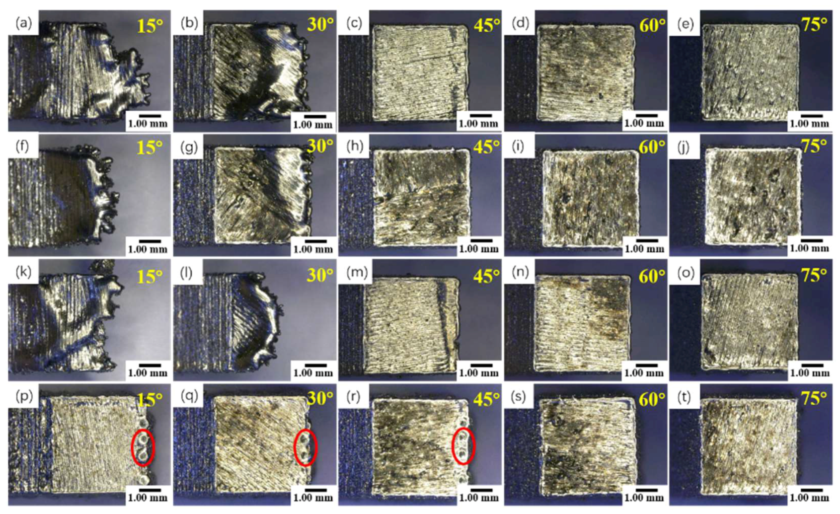
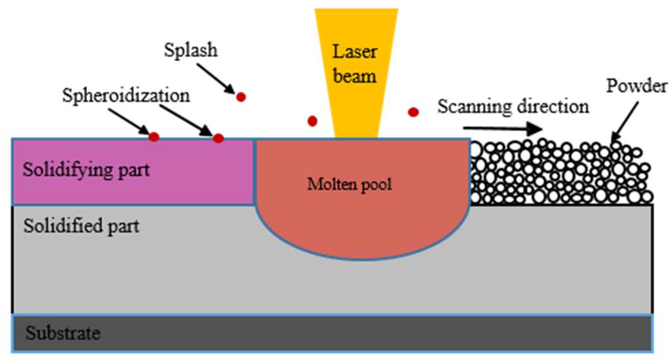
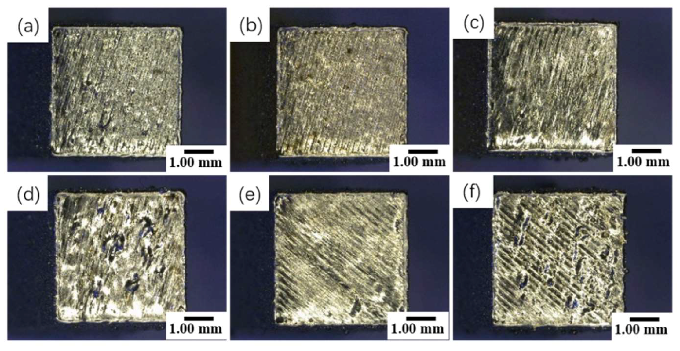
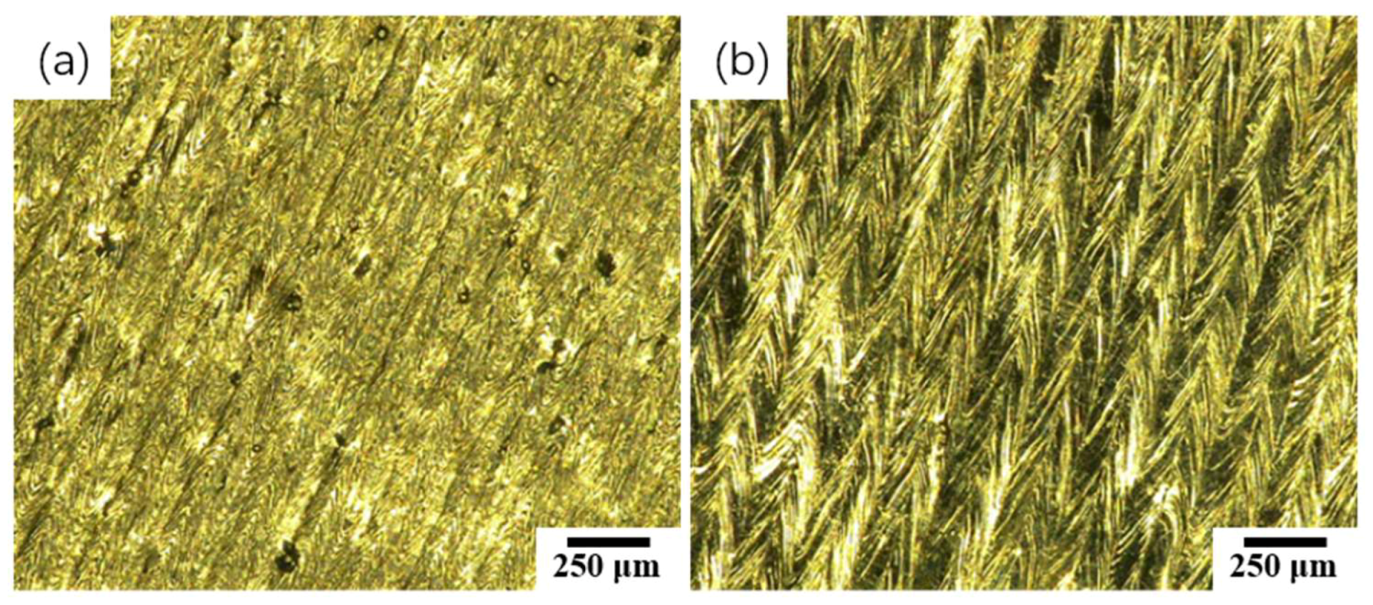
3.1. 316L Forming Surface Quality Analysis

The upper surface topography of different scanning strategies (a–o) and overhanging structures with additional support (p–t) is shown in Figure 7. Due to the lower forming angle of 15°–30°, other scanning strategies cannot be formed except for the additional support strategy. The chessboard scanning strategy can ensure the upper surface forming quality of 30°, and the missing of materials in the stripe strategy is the most serious.
As shown in Figure 8c, in the stripe scanning process, some scanning lines are not supported and rely entirely on the transverse bonding force of melted materials. In the case of insufficient bonding force, materials are prone to be missing, which results in the process defects of collapse. Due to the other scanning method, after lamination (as shown in Figure 8b), even if some areas are overhanging, the remaining areas can be supported by not only the transverse bonding force but also the materials of the bottom in the structure to ensure the lap joint effect, so the forming effect is excellent. The forming quality can be guaranteed by the additional support component from 15° to 30°. There are overhanging defect marks on the forming upper surface (red circle of Figure 7) because of the unreasonable additional support, and the defect can be eliminated by adjusting the position of the additional support.
The forming quality with the angle 45°–75° above the limit forming angle is excellent, and the meander scan strategy is better than the chessboard scan and stripe scan in the upper surface forming quality. Although the additional support can ensure good forming effect, the surface spheroidization is still serious. As shown in Figure 9, the spheroidizing defect happened by spatter. The irregular spheres spattered by excessive laser power during scanning forming solidify and are prone to forming the upper surface spheroidizing phenomenon.
Warpage and slag hanging easily happen when SLM is used to form suspension structures. The reason for these defects lies in the vast quantities of heat generated by the interaction between the radiated laser and the powder material in the forming process. The heat conductivity of metal powders is not as good as that of solidified metals, so heat easily accumulates to form larger melting pools, resulting in slag hanging and overburning defects. So it is necessary to control the energy density of the laser when forming the surface of the hanging structure.
The low energy density is used from the suspension scanning laser, and the forming effect will be improved. In addition, rapid heat dissipation can prompt liquid metal to solidify in time, thus avoiding suspension defects and improving the forming effect of the suspension structure. Therefore, the control of laser scanning process parameters of the overhanging surface is very important to the forming quality of the suspension structure. Since the underside overhanging surface is directly in contact with the powder, a smaller energy density should be used to prevent burn-through, thereby a better quality of the underside overhanging surface can be obtained.
The topography of the overhanging structure is shown in Figure 10 for different scanning strategies. The quality of the side surface corresponds to the upper surface forming effect; with the inclination angle increased, the forming quality becomes better than before. The forming quality is poor under the minimum forming angle, in which the chessboard scan is best and the stripe scan is the worst. The forming effects of various scanning strategies above the limit forming angle are favorable, and the best forming quality can be obtained, wherein the meander scan strategy is optimal. Different scanning strategies for forming a 30° overhanging structure are shown in Figure 10b,g,l, and the chessboard scan forming effect is relatively favorable, followed by the meander scan, and the stripe scan forming effect is the worst.

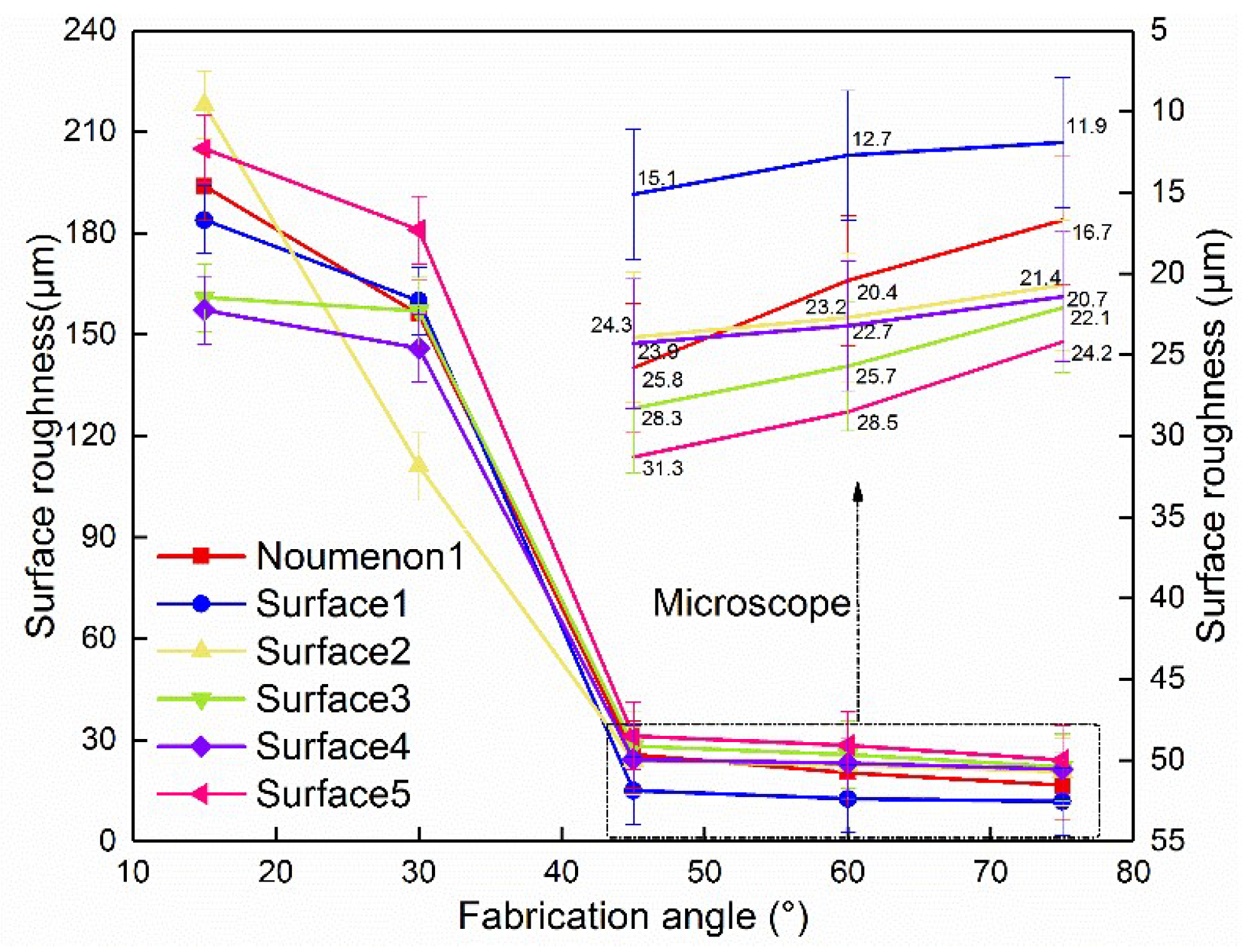
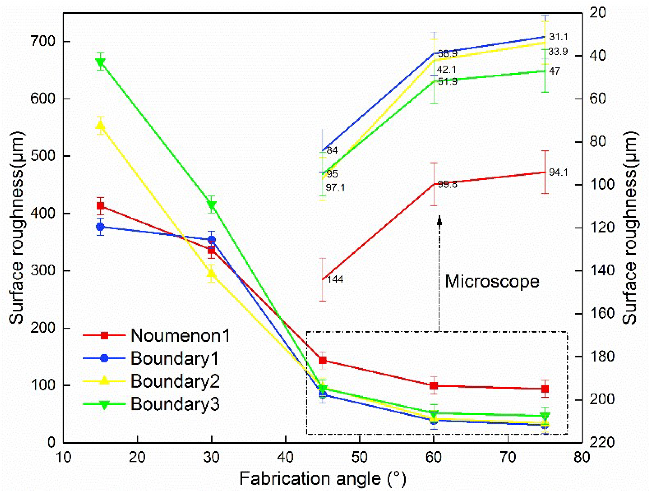
3.2. 316L Surface Roughness

The surface roughness of the upper overhanging surface formed by different optimization processes is shown in Figure 11. During the forming process with the fabrication angle from 15° to 75°, as the angle increases, the surface roughness decreases, and the surface forming quality is favorable. The forming quality and surface roughness is better when the forming angle of the overhanging surface is larger and the forming quality of the upper surface layer is also better. The values of upper surface roughness after optimization with the fabrication angle of 45°–75° are all below 30 μm in the experiment. With the increasing of the remelting power of the upper surface, the upper surface morphology deteriorates (Figure 12c–e), and the value of upper surface roughness increases. Due to the thickness of the forming layer being 50 μm, the higher laser power increases the splash phenomenon, resulting in an increase of surface spheroidization (Figure 12d), and the surface quality deteriorates. The number of laser scans also has an effect on the upper surface formation. The higher power scanning twice results in a poor surface topography, as shown in Figure 12f. The smaller power scanning twice has some improvement on the surface. As shown in Figure 13, the spheroidization phenomenon almost disappears with respect to the primary remelting surface. However, due to the instability of the process and the difference in the scanning directions, the surface is uneven, as shown in Figure 12e. The result shows that the best remelting technology is using 110 W power laser, and the upper surface roughness value can be as low as 11.9 μm.
The surface roughness of the forming underside overhanging surface with different scanning strategies is shown in Figure 14. The overhanging structure is formed below the limit forming angle, and the chessboard scanning strategy is best for forming. The meander scanning above the extreme forming angle is more favorable for forming. Due to the unique scanning method of meander scanning, partition scanning, the board has a poor lap joint effect between the overhanging area and the other area when forming the overhanging structure. When the overhanging structure is formed below the forming angle using meander scanning or stripe scanning, the single line directly acts on the powder, and the chessboard scan has corresponding support and can obtain the better forming effect. The number of boundary scanning has a great influence on the underside overhanging surface of the shaped structure. The underside surface roughness value of the suspension structure with twice scanning 75° is reduced from 94.1 μm to 31.1 μm. The number of boundary scanning can improve the forming quality of the overhanging structure. The multiple scanning of the boundary is similar to the remelting of the narrow boundary by the laser and is beneficial to improve the forming quality. Thus multiple boundary scanning is beneficial to consolidate the forming quality of the underside overhanging surface. The lower laser power also has a good effect on the improvement of the underside overhanging surface. The surface roughness value of the underside overhanging surface increases with the increase of the laser power, and the boundary scanning with the 110 W power laser has the best underside surface roughness quality.
The profile of the upper and underside overhanging surfaces of the overhanging structure is observed under the SEM. As shown in Figure 15, the defect of the sticky powdery phenomenon is more serious both in the upper and underside overhanging surfaces. Current research on the phenomenon of sticky powder shows that there is no better solution than using postprocessing to improve the quality of the overhanging surface. After sandblasting in the later process, it was found that the amount of powder adhering to the overhanging surface can be effectively reduced, and the forming quality of the overhanging surface greatly improved. The forming precision of the 45° suspension block formed in different directions of the x, y, and z (Figure 4) is shown in Table 4. The forming effect is good in this experiment, and the forming accuracy error (x1, y1, z1) is within 0.4 mm. The scanning with additional support has the best forming precision, and the remelting of boundary is beneficial to improve the forming precision. The effect of the meander scanning forming the overhang structure is better than the chessboard and the stripe scanning, and the forming precision is worse with the increasing of the remelting power.

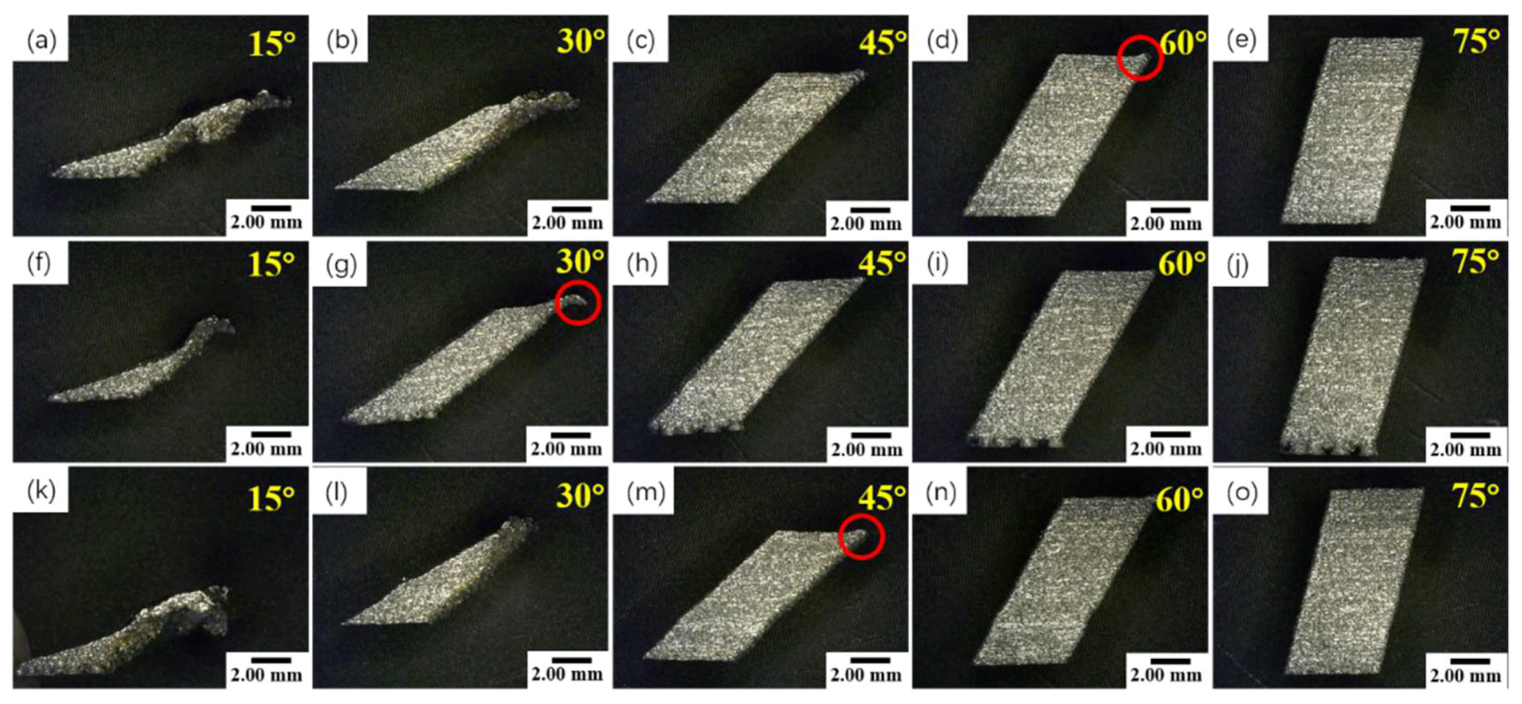
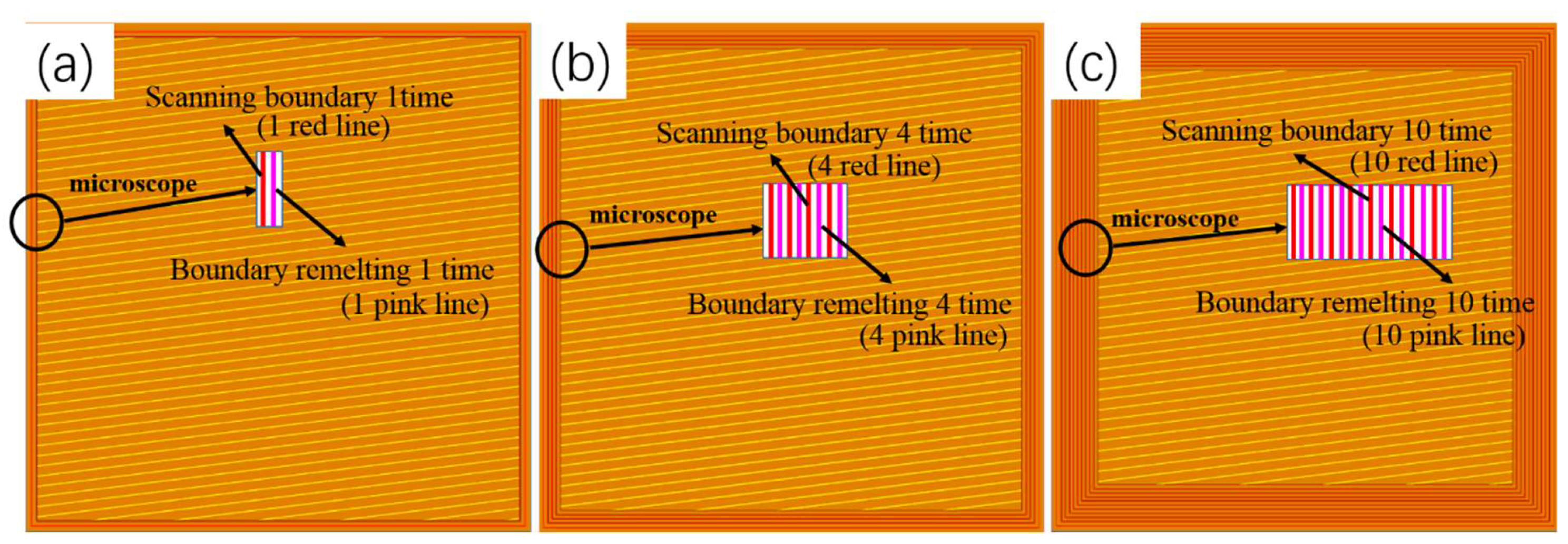
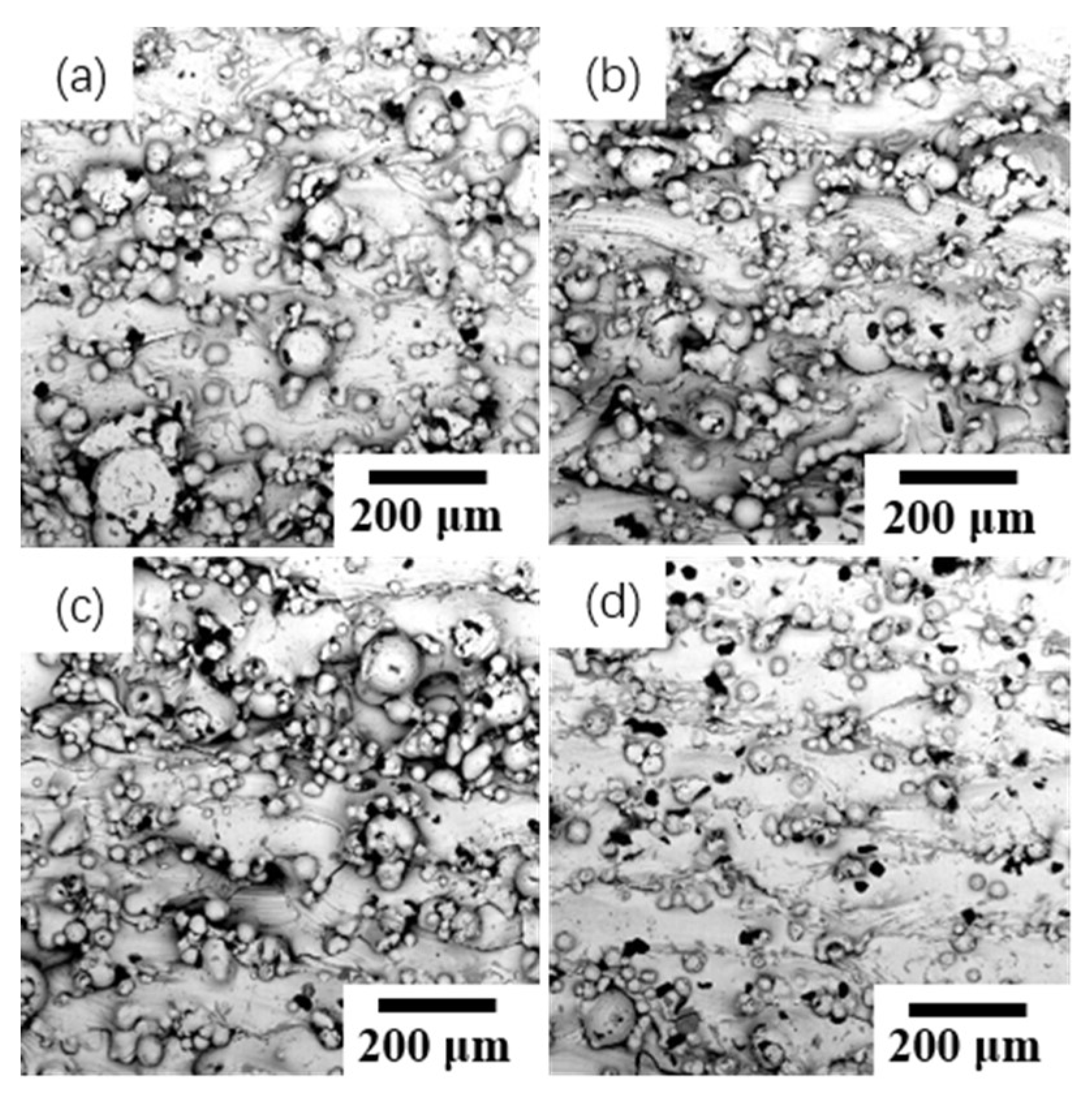
3.3. Chrome–Nickel Alloy Steel Forming Surface Quality Analysis

Considering the result of the 316L stainless steel powder forming experiment, the chrome–nickel alloy steel powder is used to form 20°, 25°, 30°, 40° overhanging structure with a layer thickness of 35 μm. The forming effect at different angles as shown in Figure 16. Compared with 316L stainless steel, the minimum forming angle (20°, 25°) can ensure good forming, and no slag, warp, and so forth in the forming experiment of chrome–nickel alloy steel powder. The overhanging structure below the limit forming angle can also achieve a good forming effect. The warping deformation is caused by joint action of the thermal stress, the tissue stress, and the residual stress existing in the rapid laser forming process. Due to the force exceeding the strength of the material, the plastic deformation happened. The overhanging structure has a large warpage deformation due to the lack of support [7], so that it is difficult to avoid the defect of overhanging in the overhang structure experiment without the support. The single layer with the overhanging portion shrinks when the scanning is completed, and the volume of the molten powder shrinks during the process of solidification, causing the overhang portion to warp upward [13]. Due to the difference of temperature between the top and bottom of the scanning layer and the uneven distribution of thermal conductivity, the upper portion of the forming layer shrinks faster than the bottom, and is prone to forming the defect of overhanging [14]. As shown in Figure 8, in the red circle is a warp phenomenon, and the warped portion is scattered around each of the suspension members. In contrast, the overhanging structure of the chrome–nickel alloy steel powder has almost no warpage, and it can be seen that the chrome–nickel alloy steel powder has better forming effect than the 316L stainless steel powder. It can be seen that the adhesion of chrome–nickel alloy is better than that of 316L stainless steel.

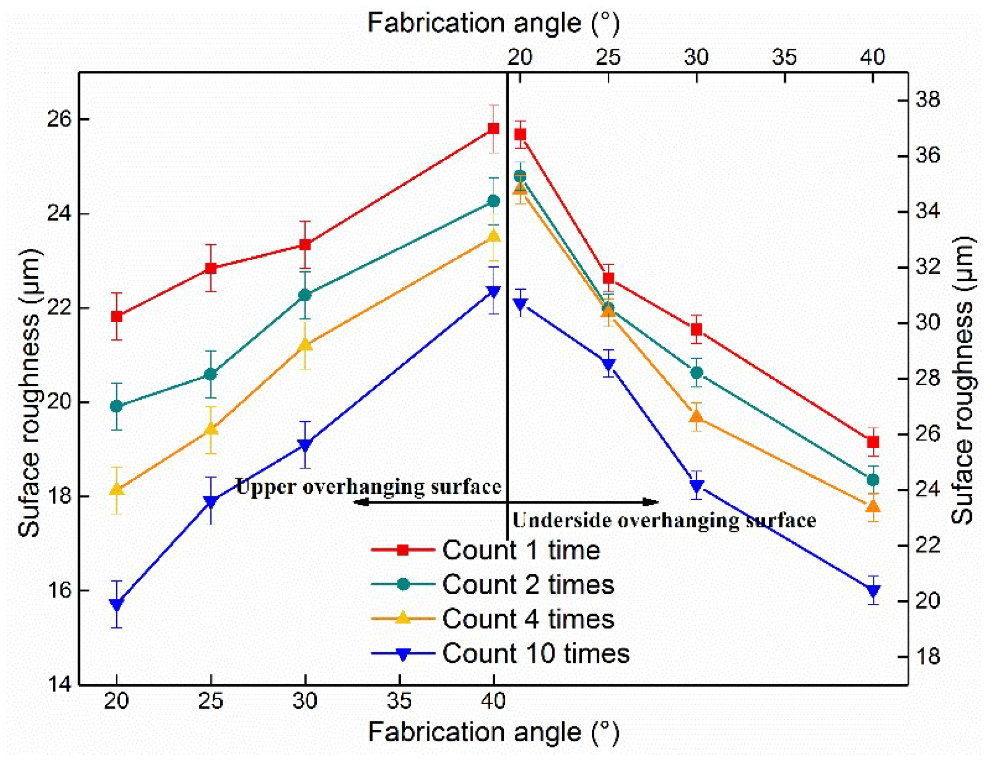
3.4. Chrome–Nickel Alloy Steel Surface Roughness

The trend curve of the influence of boundary counting strategy on overhanging surface roughness is shown in Figure 17. The different trends of the upper and underside overhanging surfaces are contrasted in the diagram. At the same time, it can be clearly found that with the increase of counting times, the surface roughness of both the upper and underside overhanging surfaces shows a downward trend. When the counting times are 10, the surface roughness value is the lowest and the forming effect is the best. The upper overhanging surface roughness value of the suspension surface on the 20° suspension structure is the lowest, which can reach 15.716 μm, and the underside surface roughness value of the suspension surface is the lowest, which is 30.716 μm.

4. Conclusions

In summary, the experimental optimization of forming overhanging structures of 316L stainless steel and chromium–nickel alloy steel was studied by selective laser melting. By using different scanning strategies, upper-surface-remelting processes, boundary-scanning powers, and boundary-counting strategies, the forming effects of the upper surface and the upper and underside overhang surface were analyzed, and the effects of the processing strategies on the surface roughness were also discussed. The conclusions are as follows:
1. The forming effect of chromium–nickel alloy is better than the 316L stainless steel below the limit forming angle in the overhanging structure.
2. Upper surface remelting can reduce the value of surface roughness, decrease the defect of surface spheroidization, and improve surface forming quality. Surface quality is better with the increase of the number of remelting, but increasing surface remelting power is not conducive to improving surface quality.
3. The optimization of boundary remelting is beneficial to the forming of suspension structure. Multiple boundary counting is beneficial to improve the forming quality of the suspension structure below the limit forming angle, and the lower scanning power is more beneficial to the forming of boundary.
4. By comparing different scanning strategies, it is found that the application of 316L stainless steel in the chessboard scanning strategy is beneficial to forming in a certain range below the ultimate forming angle, and the forming quality beyond a certain range is still not optimistic. The meander scanning strategy is suitable for forming suspension structures above the limit forming angle.

Author Contributions

Data curation, W.S. and P.W.; Formal analysis, W.S. and P.W.; Investigation, Y.L.; Methodology, P.W.; Resources, Y.L.; Supervision, Y.L.; Validation, G.H.; Visualization, G.H.; Writing—original draft, P.W.; Writing—review & editing, W.S., P.W., and Y.L.

Funding

This work was supported by grant 51505006 from the National Natural Science Foundation of China.

Conflicts of Interest

The authors declare no conflict of interest.

References

  1. Raj, B.; Mudali, U.K. Materials development and corrosion problems in nuclear fuel reprocessing plants. Prog. Nucl. Energy 2006, 48, 283–313. [Google Scholar] [CrossRef]
  2. Boyer, R.R. An overview on the use of titanium in the aerospace industry. Mater. Sci. Eng. 1996, 213, 103–114. [Google Scholar] [CrossRef]
  3. Gu, D.D.; Wang, Z.Y.; Shen, Y.F.; Li, Q.; Li, Y.F. In-situ TiC particle reinforced Ti–Al matrix composites: Powder preparation by mechanical alloying and Selective Laser Melting behavior. Appl. Surf. Sci. 2009, 255, 9230–9240. [Google Scholar] [CrossRef]
  4. Kothari, K.; Radhakrishnan, R.; Wereley, N.M. Advances in gamma titanium aluminides and their manufacturing techniques. Prog. Aerosp. Sci. 2012, 55, 1–16. [Google Scholar] [CrossRef]
  5. Chianeh, V.A.; Hosseini, H.R.M.; Nofar, M. Micro structural features and mechanical properties of Al–Al 3 Ti composite fabricated by in-situ powder metallurgy route. J. Alloys Compd. 2009, 473, 127–132. [Google Scholar] [CrossRef]
  6. Kruth, J.P.; Mercelis, P.; Vaerenbergh, J.V.; Froyen, L.; Rombouts, M. Binding mechanisms in selective laser sintering and selective laser melting. Rapid Prototyping J. 2005, 11, 26–36. [Google Scholar] [CrossRef]
  7. Van Vaerenbergh, J. Benchmarking of SLS/SLM processes. In Proceedings of the Ims Rapid Manufacturing Network Rapid Product Development Session Enabling Processes, Stuttgart, Germany, 20 October 2005. [Google Scholar]
  8. Yasa, E.; Craeghs, T.; Badrossamay, M.; Kruth, J.P. Rapid manufacturing research at the catholic university of leuven. In Proceedings of the US—TURKEY Workshop On Rapid Technologies, Istanbul, Turkey, 24–25 September 2009. [Google Scholar]
  9. Lott, P.; Schleifenbaum, H.; Meiners, W.; Wissenbach, K.; Hinke, C.; Bültmann, J. Design of an optical system for the in situ process monitoring of selective laser melting (slm). Physics Procedia. 2011, 12, 683–690. [Google Scholar] [CrossRef]
  10. Khan, M.; Sheikh, N.A.; Jaffery, S.H.I.; Ali, L.; Alam, K. Numerical simulation of meltpool instability in the selective laser melting (slm) process. Lasers Eng. 2014, 28, 319–336. [Google Scholar]
  11. Alkahari, M.R.; Furumoto, T.; Ueda, T.; Hosokawa, A. Melt pool and single track formation in selective laser sintering/selective laser melting. Adv. Mater. Res. 2014, 933, 196–201. [Google Scholar] [CrossRef]
  12. Yong-qiang, Y.; Jian-bin, L.; Di, W.; Zi-yi, L. A study of 316L stainless steel non-horizontal overhanging surface in selective laser melting. Mater. Sci. Eng. 2011, 19, 94–99. [Google Scholar]
  13. Jun, H.; Yi-ping, T.; Bing-heng, L.; Dian-liang, W. Research on supporting design rules for non-horizontal undersurface of parts in rapid prototyping by light curing. Chin. J. Mech. Eng. 2004, 40, 155–159. [Google Scholar]
  14. Tao, M. Research on several key problems in rapid prototyping technology of laser selective sintering. Ph.D. Thesis, Jiangsu University, Jiangsu, China, 2003. [Google Scholar]
Figure 1. The equipment workspace of Renishaw AM400.
Metals 09 00385 g001
Figure 2. The schematic of forming experiment piece.
Metals 09 00385 g002
Figure 3. Powder characteristics and composition content: (a) morphology of 316L stainless steel powder; (b) composition content of 316L power; (c) morphology of chrome–nickel alloy steel powder; (d) composition content of chrome–nickel alloy steel.
Metals 09 00385 g003
Figure 4. Schematic diagram and physical drawing of the 316L stainless steel: (a) 15°; (b) 30°; (c, f) 45°; (d) 60°; (e) 75°.
Metals 09 00385 g004
Figure 5. Schematic diagram of scanning strategy.
Metals 09 00385 g005
Figure 6. Boundary count (Corresponding Table 3, No. 1, 4, 5) (red line: scanning boundary; pink line: boundary remelting): (a) 1 time; (b) 4 times; (c) 10 times.
Metals 09 00385 g006
Figure 7. Different scanning strategies and support for adding surface features of the formed overhang structure (corresponding Table 2, No. 1–4): (ae) meander; (fj) chessboard; (ko) stripe; (pt) support.
Metals 09 00385 g007
Figure 8. Effect diagram of different scanning strategies after lamination: (a) meander; (b) chessboard; (c) stripe.
Metals 09 00385 g008
Figure 9. Surface spheroidization defect formation mechanism.
Metals 09 00385 g009
Figure 10. Side profile of shaped suspension structures with different scanning strategies (corresponding Table 2, No. 1–3): (ae) meander; (fj) chessboard; (ko) stripe.
Metals 09 00385 g010
Figure 11. Different optimization schemes to form the surface roughness of the overhanging structure (corresponding Table 2, No. 1, 8–12).
Metals 09 00385 g011
Figure 12. 75° upper surface topography (corresponding Table 2, No. 1, 8–12): (a) noumenon1; (b) surface1; (c) surface2; (d) surface3; (e) surface4; (f) surface5.
Metals 09 00385 g012
Figure 13. Remelted surface topography (corresponding Table 2, No. 8, 11): (a) 110 W power laser surface remelting once; (b) 110 W power laser surface remelting twice.
Metals 09 00385 g013
Figure 14. Different optimization schemes for forming overhanging surface roughness of overhanging structures (corresponding Table 2, No.1, 5–7).
Metals 09 00385 g014
Figure 15. Different optimization schemes for forming overhanging surface roughness of overhanging structures: (a–b) upper overhanging surface; (c–d) underside overhanging surface.
Metals 09 00385 g015
Figure 16. Side profile of the overhanging structure at different angles (corresponding Table 3, No. 1): (a) 20°; (b) 25°; (c) 30°; (d) 40°.
Metals 09 00385 g016
Figure 17. Boundary scanning strategy affects surface roughness trend (corresponding Table 3, No. 2–5).
Metals 09 00385 g017
Table 1. Block-forming test data sheet of 316L stainless steel.
NumberTest PlanLaser Power (W)Exposure Time
(μs)
Point Distance
(μm)
Hatch Space (μm)Scanning StrategyRemark
1Noumenon12008040110MeanderThe system scans the boundary once by default.
2Noumenon22008040110Chessboard
3Noumenon32008040110Stripe
4Support
5Boundary111010020100 Scan the boundary again according to the setting parameters.
6Boundary216010020100
7Boundary320010020100
8Upper surface11108040110MeanderScan once by setting parameters.
9Upper surface21608040110Meander
10Upper surface32008040110Meander
11Upper surface41108040110MeanderScan again by setting parameters.
12Upper surface51608040110Meander
Table 2. Block-forming scheme of 316L stainless steel.
NumberTest PlanNumberTest Plan
1Noumenon12Noumenon2
3Noumenon34Noumenon1 + Support
5Noumenon1 + Boundary16Noumenon1 + Boundary2
7Noumenon1 + Boundary38Noumenon1 + Upper surface1
9Noumenon1 + Upper surface210Noumenon1 + Upper surface3
11Noumenon1 + Upper surface412Noumenon1 + Upper surface5
Table 3. The parameters of chromium–nickel alloy steel block-forming experiment.
NumberTest PlanLaser Power
(W)
Exposure Time
(μs)
Point Distance
(μm)
Hatch Space (μm)Scanning StrategyRemark
1Noumenon11008040100Meander
2Boundary180804040 Count 1 time
3Boundary280804040 Count 2 times
4Boundary380804040 Count 4 times
5Boundary480804040 Count 10 times
Table 4. Block forming accuracy table.
GroupX (mm)x’ (mm)x1 (mm)y (mm)y’ (mm)y2 (mm)z (mm)z’ (mm)z3 (mm)
155.090.0955.080.087.077.150.08
255.150.1555.120.127.077.290.12
355.110.1155.090.097.077.180.11
455.040.0455.050.057.077.080.01
555.060.0655.070.077.077.130.06
655.140.1455.160.167.077.350.28
755.210.2155.220.227.077.430.36

