Article

Process Parameters Decision to Optimization of Cold Rolling-Beating Forming Process through Experiment and Modelling

School of Mechanical and Precision Instrument Engineering, Xi′an University of Technology, Xi’an 710048, China
*
Author to whom correspondence should be addressed.
Metals 2019, 9(4), 405; https://doi.org/10.3390/met9040405
Submission received: 8 March 2019 / Revised: 28 March 2019 / Accepted: 31 March 2019 / Published: 2 April 2019
(This article belongs to the Special Issue Numerical Modelling and Simulation of Metal Processing)

Abstract

:
The cold roll-beating forming (CRBF) process is a particular cold plastic bulk forming technology for metals that is adequate for shaping the external teeth of important parts. The process parameters of the CRBF process were studied in this work to improve the process performance. Of the CRBF process characteristics, the forming forces, tooth profile angle, surface roughness, and forming efficiency were selected as the target indices to describe the process performance. Single tooth experimental tests of ASTM 1045 steel were conducted with different roll-beating modes, spindle rotation speeds, and feed speeds. Using analysis of variance (ANOVA) and regression analysis, the influence of the process parameters in each index was investigated, and regression models of each index were established. Then, the linear weighted sum method and compound entropy weight method were used to determine the process parameters for multi-objective optimization. The results show that the impact capacity and optimum value range of the process parameters vary in different indices, and that, to achieve the comprehensive optimum effect of a small forming force, high product quality, and high forming efficiency, the optimal process parameter combination is the up-beating mode, a spindle rotation speed of 801 r/min, and a feed speed of 960 mm/min.

1. Introduction

As important mechanical products, gears, spline shafts, and other transmission parts are widely used in various mechanical products [1,2], the rapid development of major industries, such as automobile, aircraft, special engineering machinery, and wind and nuclear power equipment, has led to a huge demand for transmission parts with higher performance [3,4]. In the production of mechanical parts, objectives such as creating a lightweight design, establishing short process chains, and improving material and energy efficiency are difficult to meet using the current cutting methods to shape the external teeth of transmission parts [3,5,6]. Plastic forming, as a near-net shape forming technology, is a promising method to solve some of the problems in traditional cutting. As such, the new process and novel production equipment have received attention [7,8]. Among the varieties of plastic forming technologies, cold roll-beating forming (CRBF) is an incremental metal bulk forming technology for forming the external teeth of high-load transmission parts, and it has the advantages of environmental protection, flexibility, and lower cost. It has a wide range of application prospects in the automobile industry, the aerospace sector, and equipment manufacturing [9,10,11].
Some studies have been carried out on the CRBF process, and some research results have been published. On the basis of the kinematics of the CRBF process, Fengkui Cui et al. [12,13] analyzed and studied the forming process of involute spline cold roll-beating in which the workpiece was continuously indexed. In view of the forming error caused by the continuous indexing motion of workpiece, a design and modification method of the rolling wheel were put forward, and a technological scheme of roll wheel manufacturing was provided that improved the geometric accuracy of involute spline CRBF. Mingshun Yang et al. [14] established a simplified mathematical model for describing the residual height of the formed tooth bottom under the assumption of rigid plastic deformation, and they discussed the influence of process parameters on the residual height of the tooth bottom. These studies illustrate the basic kinematic characteristics of the CRBF process. On the basis of these studies, there have been some numerical simulation and experimental studies dedicated to the metal deformation characteristics and mechanism of the CRBF process. Fengkui Cui [15] and Xinqin Gao [16] established a simplified finite element model of the CRBF process and simulated the material behavior and changes in the principal stress, hydrostatic pressure, and principal strain of the deforming area. Then, the metal deformation characteristics of the CRBF process were given. On the basis of the deformation characteristics, a constitutive model of the material for the CRBF process was further studied [17,18,19]. The results of these studies provide guidance for simulating the CRBF process and explaining the forming mechanism. Through the simulation of a complete tooth groove CRBF process, Xiaoming Liang et al. [20] analyzed changes in the radial and tangential forming force throughout the whole forming process and discussed the influence of the roll-beating mode on forming forces. Fengkui Cui et al. [21] linked the plastic deformation of metal to the surface residual stress that occurs during the CRBF process by observing the grains changing in the spline tooth profile section, and they explained the residual stress generation in terms of the forming mechanism. Zhiqi Liu et al. [11] performed an experimental study on the CRBF mechanism from the microcosmic point of view. The depth of the microhardness layer and the model of grain evolution during the CRBF process were established. Fengkui Cui et al. [10,22,23] measured the residual stress, hardness, and roughness of a spline surface fabricated by CRBF, and a series of empirical expressions were obtained to describe the effects of the roll-beating speed and feed rate on these indices.
On the basis of clear characteristics and the forming mechanism of CRBF, there is a need for further quantitative discussion about the effect of process parameters on the CRBF process to promote the practical application of CRBF. In particular, to improve the process performance of CRBF, it is necessary to clarify the influence of process parameters on the forming force, forming quality, and forming efficiency. In view of this situation, ASTM 1045 steel was tested by a CRBF experiment on the outer teeth. The empirical formulas of the indices of the forming force, product quality, and forming efficiency under different process parameters were established according to the experimental results. The aim of this study is to determine the influence of different process parameters on CRBF and provide a method to realize the comprehensive optimization of the forming force, forming quality, and forming efficiency by judiciously selecting the appropriate process parameters.

2. Materials and Methods

2.1. Description of CRB Process

CRBF is a special intermittent free cold forging process. It is different from the quasi-static forming process of die forging, drawing, rolling, etc. During the CRBF process, the metal is subjected to intermittent impacts at a certain frequency, and the deformation produced by each impact is small. The deformation zone continuously migrates through the feed of the workpiece, and the amount of deformation gradually accumulates to accomplish the final forming purpose. For different types of parts, the process of forming the external tooth profile in CRBF can be described by the single tooth groove forming process. A schematic diagram is presented in Figure 1. The roller is assembled eccentrically on the spindle, and the geometric profile of the roller is designed according to the profile of the target tooth. The spindle rotation drives the roller to roll-beat the workpiece, and the roller can rotate around the roller shaft as it beats and rolls the workpiece. During the forming process, the workpiece is fed continuously to accumulate the plastic deformation caused by each roll-beating of the roller. Finally, a tooth groove consistent with the profile of the target tooth is formed on the workpiece. When the feed direction of the workpiece is clear, we can change the rotation direction of the spindle to choose the mode of the CRBF process. In order to express this clearly in a way similar to the milling process, CRBF can be defined by a coordinate system in which the y-axis is the feed direction of the workpiece and the z-axis is perpendicular to the workpiece to be processed. As such, when the angular velocity direction of the spindle rotation is consistent with the x-axis, it is an up-beating mode; when it is inconsistent, it is a down-beating mode. Through the above description of the CRBF process, it can be understood that the main processing parameters are spindle rotation speed, feed speed, and roll-beating mode.

2.2. Material Characterization

The material of the workpieces was ASTM 1045 steel for the CRBF experiment because it has good mechanical properties and manufacturability, and it is widely used to manufacture functional parts. The main chemical composition of the material is shown in Table 1.
The main deformation of materials during the forming process is compression deformation. After normalization, a compression test was carried out by a 100-kN mechanical testing machine (MTS Inc., Eden Prairie, MN, USA). The size of the sample was Φ6 mm × 10 mm, and the down-pressure velocity was 0.5 mm/min. Figure 2 illustrates the experimental result.
For the CRBF experiment, the material was made into workpieces by wire-electrode cutting and milling. The length along the feed direction of the workpiece was 45 mm. The surface hardness and roughness of the workpieces were HV 180–220 and Ra 0.8–1.6, respectively.

2.3. Experimental Setup

According to the principle of the external tooth groove CRBF, a CRBF device was designed and realized by a horizontal milling machine to carry out the forming experiment, as shown in Figure 3. In this CRBF device, the roller is eccentrically mounted on the spindle through a roller shaft and two bearings (INA NKXR20Z, INA Inc., Nuremberg, Germany), and the axial clearance is adjusted by two sets of gaskets. The radius of the trajectory of the roller edge is 74 mm, and the roller is made of 20CrMnTi. After quenching and tempering treatment, the surface of the roller is conditioned and Rockwell hardness number reaches 58–64 HRC. The dimensions and tooth detail of the roller are shown in Figure 4.
The spindle rotation speed, feed speed, and roll-beating mode were chosen as the research factors. The spindle rotation speeds are 475 r/min, 950 r/min, and 1500 r/min. The feed speeds of the workpiece are 30 mm/min, 60 mm/min, 120 mm/min, 240 mm/min, 480 mm/min, and 960 mm/min. The different roll-beating modes of the CRBF process were realized by changing the rotation direction of the spindle. The experiments were carried out with all combinations of all process parameters at all levels. The experimental implementation scheme is shown in Table 3. The roll-beating depth was set at 2.5 mm, and the workpiece was coated with lubricating oil.
During the forming process, a piezoelectric three-direction force sensor PCB261A03 (PCB Inc., Buffalo, NY, USA) was used to obtain forming force data. After removing oil from the surface of the experimental tooth grooves with a metal cleaning agent, the three-dimensional macroscopic geometrical data of the surface geometry of the tooth grooves were measured and obtained by the super 3-D microscope system VHX-5000 (Keyence Inc., Osaka, Japan). The measuring accuracy of this instrument is 0.01 mm. The surface roughness of the tooth wall was measured by laser confocal microscopy using the DCM 3D (Leica Inc., Wetzlar, Germany).

3. Results

For metal bulk forming technology, forming forces, forming quality, and forming efficiency are the important objectives that we are interested in optimizing.
In the coordinate system described in Figure 1, the forming force in the x-direction was low during the forming process because of the geometric symmetry of the tooth shape of the roller. The forming force in the z-direction Fz is the main forming force in the CRBF process, and the forming force in the y-direction Fy determines the main shaft torque load and the workpiece feed system load of the forming equipment. Fz and Fy directly affect the design of the forming equipment and the implementation of the forming process.
Figure 5 shows Fz and Fy measured in the up-beating and down-beating modes for a spindle rotation speed of 475 r/min and a feed speed of 240 mm/min. For the same forming equipment and workpiece, the total time of the CRBF process is mainly related to the feed speed. Figure 5 shows that the actual roll-beating lasts nearly 16.5 s when the feed speed is 240 mm/min and that the forming forces of CRBF form a pronounced sharp pulse. This is consistent with the characteristics of intermittent impact loading in the CRBF process. In either mode, the Fz peak of each roll-beating gradually increases in the early stage of the forming process; then, it reaches the maximum and remains stable, after which it decreases gradually until the end of the forming process. Therefore, Fzam—the average value of the Fz peak of each roll-beating in the stability region—is used to characterize Fz. The Fy peak of each roll-beating during the CRBF process also has increasing, stable, and decreasing regions. However, the Fy peak of each roll-beating in the stable region is not the maximum of the whole forming process, differing from the pattern for Fz and varying for different roll-beating modes: In the up-beating mode, the maximum Fy is obtained between the increasing and stable regions, and the maximum Fy in the down-beating mode occurs before the end of the stable region. For practical applications, the maximum Fy of the whole forming process is worth more than the average value of the Fy peak of each roll-beating in the stable region. As such, to express the maximum Fy of the whole forming process, Fymax is used to characterize Fy in the CRBF process.
For product quality attributes, this paper mainly considers geometric accuracy, surface roughness, and hardening. The geometry accuracy of the single tooth profile is usually described by profile error and lead error. The lead error is primarily determined by the feeding straightness of the feed system of the forming equipment and the axial positioning accuracy of the spindle rotation. The lead error is not sensitive to the process parameters analyzed in this paper. There is an obvious tooth profile error in the tooth groove formed by CRBF because, in the real forming process, the material has elastic recovery, which produces profile errors. These profile errors mainly appear as angle errors in the tooth profile, as shown in Figure 6. When the roller roll-beats the workpiece, the metal extends along the tooth profile. After the roller leaves the workpiece, the metal flowing along the tooth profile has elastic recovery, which ultimately makes the angle of the tooth groove wall smaller than the tooth profile angle of the roller. The above discrepancy in the tooth angle is defined as the angle error of the tooth profile and is represented by β. For a different roll-beating mode, roll-beating speed, and feed speed, the stress field and hardening of metals are different, and this variation affects the elastic recovery. As such, β is obviously affected by the process parameters. Therefore, β is used to characterize the geometry accuracy in this paper.
Transmission parts mainly transfer power through tooth wall meshing. Reducing the surface roughness of the tooth wall directly improves the service life and transfer efficiency of the parts and reduces the working vibration. Therefore, the surface roughness is an important standard of surface quality. To facilitate measurement, each groove formed in the experiment was divided into two parts by the middle of the tooth bottom using wire-electrode cutting. The length of the specimen was 10 mm along the tooth’s lead direction, as shown in Figure 7. It can be seen that the desired surface finish of the tooth wall can be achieved by grinding.
From the measurement of the surface roughness of the tooth wall, it was observed that the micro-morphology of the tooth wall formed by CRBF is an irregular fish-scale pattern, as shown in Figure 8. This phenomenon is caused by the multiple rolling of the surface of the workpiece and the rotation of the roller in the roll-beating process. Therefore, surface roughness Sa of the tooth wall is used to characterize the surface quality.
The metallographic structure of the metal after CRBF is shown in Figure 9. As a result of the strong plastic deformation of the metal during the forming process, the grain was refined and highly fibrous on the tooth wall and tooth bottom. Because of the impact loading of CRBF, the grain refinement and fibrosis are mainly concentrated in the surface layer of the metal. Comparing the metallographic structure of the tooth top, tooth wall, and tooth bottom, it can be found that the grain refinement degree of the tooth bottom near the tooth wall is the highest, and the grain refinement degree is the weakest at the tooth top.
The hardness of each part was measured. The hardness at the position of the tooth top, tooth wall, and tooth bottom near the tooth wall is 256, 292, and 310 HV, respectively. The hardness of the internal metal, which does not change in structure, is 210 HV. This is consistent with the change in grain refinement. The hardness of the tooth wall resulting from the use of different process parameters was measured. The results show that the hardening rate is between 135% and 145%, and the hardening degree is not very sensitive to the change in process parameters. This is because the change in processing parameters has little effect on the metal deformation after final forming. Therefore, workpiece hardening is not considered as an index of forming quality in this study.
For the forming efficiency, the feed speed is directly used to characterize the forming efficiency. The research objectives and their corresponding indices are shown in Table 2.
The experimental results of the above indices and corresponding process parameters are listed in Table 3, in which the results for β and Sa are the average of the two sides of the tooth wall. In addition, in order to facilitate mathematical representation and analysis, the variable m is used to denote the roll-beating mode: m = 1 represents up-beating and m = −1 represents down-beating.

4. Discussion

3.1. Significance Analysis of Process Parameters to Objectives

ANOVA was used to test the significance of each process parameter, and the results are shown in Table 4. The probability of F(0.05) > F is represented by the P value of the right-sided test. When the F value of the objective is greater than F(0.05) and the P value is less than 0.05, the factor has a significant effect on the objective [24,25].
The results of ANOVA show that for the ranges of the tested levels, the three process parameters have a significant influence on Fzam, for which the most important factor is feed speed, the second most important is the roll-beating mode, and the least important is the spindle rotation speed. The interaction item m × w is significant for Fzam, and m × f is considered statistically non-significant. The F value of w × f is larger than F(0.05), but the P value is bigger than 0.05. These values indicate that, although the influence of w × f on Fzam is very weak, it still has some impact.
All the tested sources of variation in Fymax are significant, and the order of importance of those sources is w > m > f > m × f > m × w > w × f.
Each process parameter has a significant influence on β, and m is the most important factor. The parameters w and f almost have the same effect on β. Of the interactive terms, m × w and m × f are significant. P > 0.05, the w × f interaction is considered statistically non-significant, but its F value is bigger than F(0.05), so its impact cannot be ignored.
For Sa, m and the interaction terms containing m are not significant. So, from a statistical view, it can be asserted that the change in roll-beating mode does not affect the roughness of the tooth wall. All the other sources are significant, and w is the most important.

3.2. Regression Models

Because m is not a continuous variable—i.e., it only takes values of 1 or −1—a piecewise function, denoted by T(w, f), that consists of two polynomial models is used to characterize the response of Fzam, Fymax, and β to the influences of the different parameters. Meanwhile, given that m is irrelevant to Sa, T(w, f) is directly used to express Sa. The functional form of T(w, f) is a polynomial model which is widely used in regression analysis and empirical modeling. The function is shown in Equation (1). In order to ensure regression accuracy, the degrees of freedom of w and f in the function T(w, f) are 2 and 3, respectively, and the interaction between w and f is accounted for.
T ( w , f ) = a 00 + a 10 w + a 01 f + a 20 w 2 + a 11 w f + a 02 f 2 + a 21 w 2 f + a 12 w f 2 + a 03 f 3
Table 5 gives the final regression model of each index. The applicable range of these regression models is within the range of the experimental parameters. The term R2 denotes the prediction capability of the regression equations. Generally, an R2 value greater than 0.9 indicates that the regression equation is acceptable for fitting the experimental data, and an R2 value greater than 0.95 indicates that all predicted values are reliable and quite close to the actual values. Apart from the R2 value of β’s regression model in the down-beating mode being slightly less than 0.95, the R2 values of all the other regression models are higher than 0.95. Furthermore, the P values of all regression models are less than 10−4, as shown in Table 4.
From the established regression models, the predicted values of the indices resulting from the process parameters in Table 3 were obtained. Then, we plotted these points to the coordinates that define the experimental values compared with the predicted values, as seen in Figure 10. The distribution of these points is not related to the form and coefficient of the regression equation but only to the fitting error. Figure 10 shows that the points are close to the straight line of y = x, and the error of the predicted values versus experimental values is distributed uniformly. These results indicate that the regression models have high fitting ability.
As such, according to the results of the above analysis, it is proved that the established regression models can effectively and reliably describe the influence of the tested process parameters on Fzam, Fymax, β, and Sa.

3.3. Influence of Process Parameters on Each Index

In accordance with the regression equations listed in Table 5, Figure 11, Figure 12, Figure 13 and Figure 14 illustrate the relation surface between each index and process parameter.
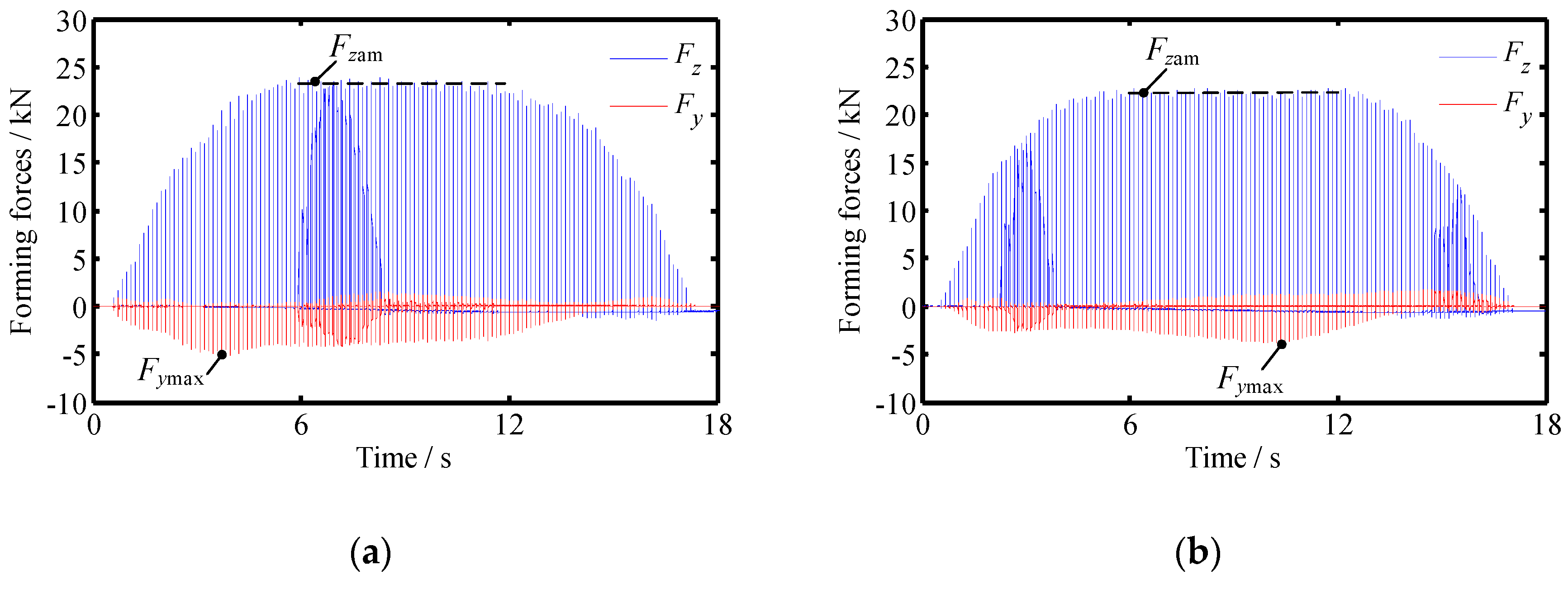
Figure 11 shows that in the different roll-beating modes, the change rules of Fzam with w and f are consistent, but the change in Fzam in the up-beating mode is larger. The value of f has a great influence on Fzam, where lower f means smaller Fzam. The degree of this effect is greater when f is less than 400 mm/min, below which Fzam decreases rapidly with decreasing f. The effect of w on Fzam varies in different f regions. When f is in the lower range, Fzam increases first and then decreases with the increase in w. At higher f values, Fzam decreases first and then increases when w increases. However, the range of Fzam changes is limited by only changing w. Therefore, the down-beating mode and low f are enough to significantly reduce Fzam.
As shown in Figure 12, the change trend of Fymax resulting from f and w varies for the different roll-beating modes, and the change range of Fymax in the up-beating mode is larger. For up-beating, with an increase in w, Fymax decreases first and then increases. Compared with w, f has a greater influence on Fymax. Increasing f leads to an obvious increase in Fymax. When f is small and w is near 900 r/min, Fymax is the smallest. In the down-beating mode, Fymax is more affected by w than f. Fymax and w are proportional to each other. In response to increasing f, Fymax increases rapidly and then decreases. As such, the down-beating mode, low w, and small f or f close to 780 mm/min are advantageous for reducing Fymax.
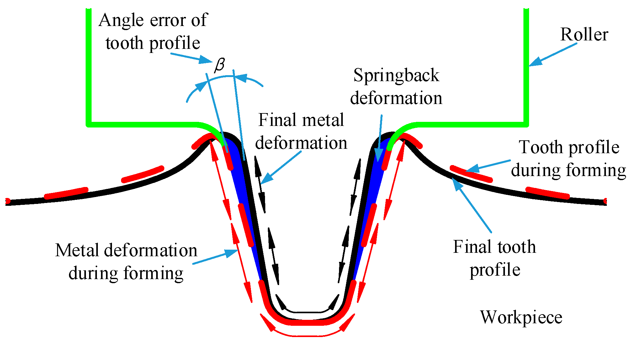
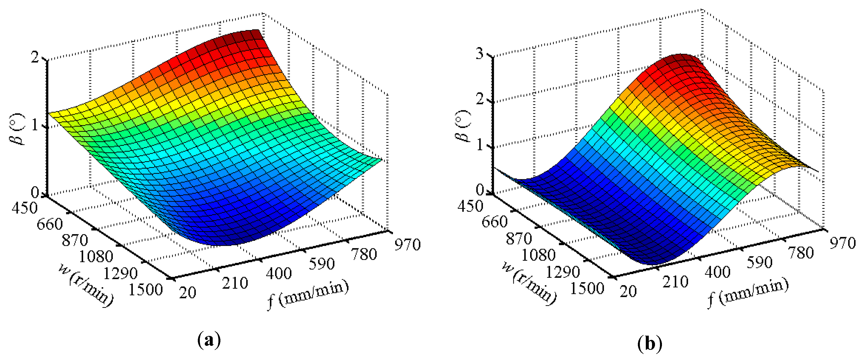
The whole change range of β is smaller in the up-beating mode. β decreases with the increase in w. In the low-w region, increasing f causes β to increase. In the high-w region, β decreases first and then increases when f grows, and the minimum β value is obtained around f = 450 mm/min. In the down-beating mode, β is weakly affected by w and decreases slightly with an increase in w. β is strongly influenced by f. As a result of increasing f, β decreases first and reaches the minimum; when f is near 240 mm/min, β increases and reaches the maximum near f = 840 mm/min. Figure 13 shows that in different roll-beating modes, setting w to 1280–1500 r/min and setting f to 30–590 mm/min allows β to be controlled at its lower level.
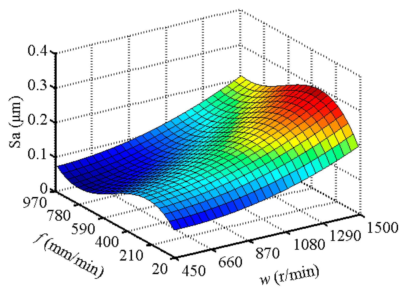
As shown in Figure 14, Sa increases when w increases. With increasing f, Sa increases rapidly first and then decreases gradually. Sa is the maximum at w = 1500 r/min and f = 350 mm/min. When w is within 450–870 r/min and f is within 600–960 mm/min, Sa is controlled under 0.1 μm.
In addition, for the single tooth forming process, a higher f value means higher forming efficiency.

3.4. Optimize

From the above analysis, it can be seen that the influence of each process parameter on the forming force, forming quality, and forming efficiency indices has its own characteristics. There are some contradictions between the ranges of the process parameters, and these conflicts result in each index having its own optimal value at the same time; in order to determine the process parameters that allow each index to achieve comprehensive optimization, the linear weighted sum method was used to establish the comprehensive evaluation function E for Fzam, Fymax, β, Sa, and forming efficiency, as shown in Equation (2).
E = i = 1 n C i e i j
In Equation (2), i denotes the ordinal number of the index (in this case, i = 1, 2, ..., 5); j is the number of the process parameter combination; eij represents the evaluation value of the ith index obtained under the jth process parameter combination; C is the weight coefficient, and the sum of the weight coefficients is 1. The function E allows corresponding weight coefficients to be assigned to each index according to the importance of each index, and it includes the linear combination of the multiple indices. It reduces the multi-objective optimization problem to the numerical optimization of the function E, which realizes the comprehensive optimization of the multiple objectives.
To solve the above, the first step is to get the evaluation value of each index so that they have the same order of magnitude. The Min-Max normalization function is used to convert the index data into the evaluation value. So, all the evaluation values of each objective range from 0 to 1. This Min-Max function takes two forms, as shown by Equations (3) and (4), in which O represents the data of each index. In this case, Fzam, Fymax, β, and Sa are normalized by Equation (3), and f is normalized by Equation (4).
e i j = max O i j O i j max O i j min O i j
e i j = O i j min O i j max O i j min O i j
In the range of process parameters, m = [−1, 1], w ∈ [475, 1500], f ∈ [30, 960], and the maximum and minimum values of each index are solved. The results are shown in Table 6.
The entropy weight method was used to determine the weight coefficients, as it has strong objectivity and is widely applicable to practical engineering optimal problems [26]. This method uses the evaluation data of a sample to calculate the entropy weight coefficient of each index as the weight coefficient of each index. In order to calculate the entropy weight coefficient, it is first and foremost necessary to determine a large enough sample of evaluation values. Given the range of the process parameters, with the interval steps of w and f set to 5, there are 77,044 combinations of the different process parameters. Then, the evaluation values for each index under each group of process parameters are calculated by the regression model in Section 3.2, Equations (3)–(4), and Table 6. As such, we get a 5 × 77,044 evaluation matrix as the sample data. Then, the entropy weight coefficient of each index is obtained by Equations (5) and (6), in which Hi represents the entropy value of the ith index, and ci is the entropy weight coefficient for the ith index. During the calculation, it is important to note that when f is 30, calculating H5 is meaningless. To avoid this, the value of 30 for f is replaced by 30.00001 in these calculations.
H i = j = 1 k e i j j = 1 k e i j ln e i j j = 1 k e i j ln k
c i = 1 H i n i = 1 n H i
However, the weight coefficient obtained by this method has a lack of horizontal comparison among the objectives. Accordingly, to reflect the importance of the different objectives, an additional subjective weight coefficient λ is added to the entropy weight coefficient to get a composite weight coefficient, which is the C in Equation (2). The composite weight coefficient can be calculated by Equation (7). The subjective weight coefficient is given according to the importance of each objective. For the CRBF process, the first considered object is the forming quality, followed by the forming force and forming efficiency. Consequently, the subjective weight coefficients of β and Sa in the evaluation of tooth profile angle error and tooth wall roughness are large. Among them, considering that the tooth wall roughness is maintained at a certain level under the different process parameters, the subjective weight coefficient of Sa is smaller than that of β. For the indices used to evaluate the forming force, compared with Fzam, Fymax is more important since it directly reflects the torque required of the spindle and the load of the feed system during the forming process. A smaller Fymax implies lower energy consumption. Therefore, the subjective weight coefficient of Fymax is slightly higher than that of Fzam. The forming efficiency and Fzam are a set of contradictory indices for CRBF. High efficiency means a large feed speed. However, with a large feed speed, Fzam is larger, as shown in Figure 11. A larger Fzam means that the forming equipment is subjected to a greater load, which speeds up the wear of the equipment parts and increases the cost of the forming process. As such, it is appropriate to assign Fzam and f the same subjective weight coefficients. The results of the weight coefficient calculations are listed in Table 7.
C i = λ i c i i = 1 n λ i c i ; i = 1 n λ i = 1
From Equations (2)–(4), the regression model of the indices, Table 6, and Table 7, the extended expression of the comprehensive evaluation function E is obtained, as shown in Equation (8).
E = { 0.5397 + 7.351 × 10 5 w 1.103 × 10 3 f 7.303 × 10 8 w 2 + 5.934 × 10 7 w f + 2.207 × 10 6 f 2 2.835 × 10 10 w 2 f 6.132 × 10 11 w f 2 1.285 × 10 9 f 3 , m = 1 0.6527 6.206 × 10 5 w 7.234 × 10 5 f 4.367 × 10 8 w 2 + 2.757 × 10 7 w f 2.002 × 10 7 f 2 2.283 × 10 10 w 2 f + 2.372 × 10 10 w f 2 + 1.1175 × 10 10 f 3 , m = 1
For the process parameter ranges, m = [−1, 1], w ∈ [475, 1500], and f ∈ [30, 960], and the surface graph of the comprehensive evaluation function E is obtained and shown in Figure 15. The coordinates of each point on the surface represent a process parameter combination and the evaluation values resulting from this process parameter combination. A higher evaluation value corresponds to a more reasonable combination of process parameters in order to achieve the comprehensive process effect of a small forming force, high forming quality, and high forming efficiency. It can be seen that in the up-beating and down-beating modes, the evaluation value of the process parameter combination is higher in the ranges of w ∈ [475, 1200] and f ∈ [600, 960], respectively. In the case of w and f, with a minimum interval of 1, the vertex coordinates of the comprehensive evaluation function surface at m = −1 and m = 1 are (850, 882, 0.6354) and (801, 960, 0.6664), respectively. Subsequently, it is concluded that for CRBF, the optimum process parameters according to the comprehensive consideration of forming forces, forming quality, and forming efficiency are the following: Up-beating mode, a spindle rotation speed of 801 r/min, and a feed speed of 960 mm/min.
With the optimal process parameters, a confirmation experiment was repeated three times, and the average values of Fzam, Fymax, β, and Sa from the experiments are shown in Table 8. A comparison of predicted and experimental results reveals that the experimental results are close to the optimal solution obtained from the predicted model. The percentage errors between the prediction results and the confirmation experimental results are less than 7%.
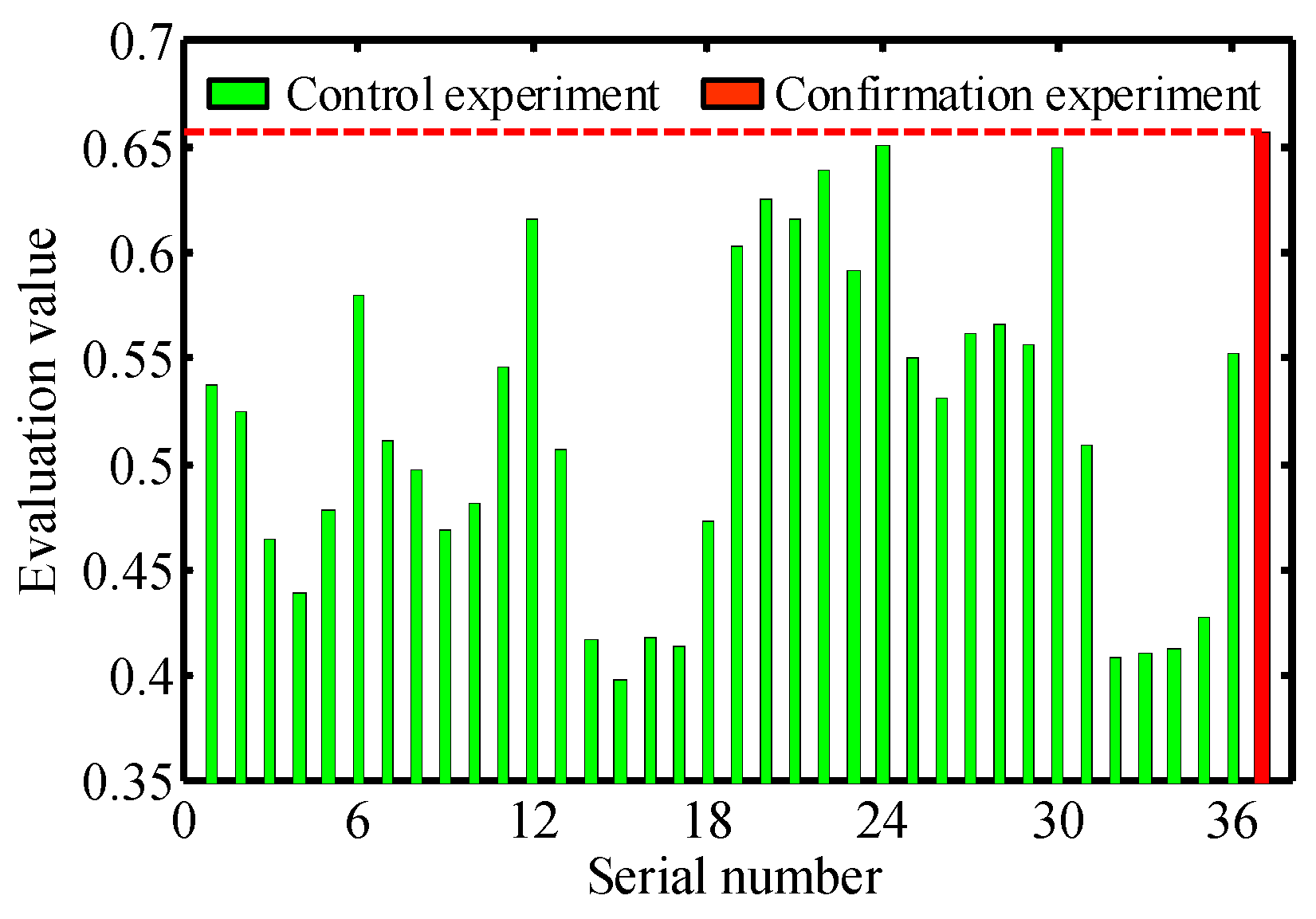
Next, taking the experiments in Table 3 as control experiments and using the measured data of each index, the comprehensive evaluation value of each experiment was obtained by Equations (2)–(4). Comparing the comprehensive evaluation values from the confirmation experiment and the control experiments, it can be seen that the control experimental results are not higher than the confirmation experimental evaluation values, as shown in Figure 16. Therefore, it can be asserted that the regression models for Fzam, Fymax, β, and Sa are correct, and the method of process parameter selection for multi-objective optimization of the CRBF process in this paper is feasible.

5. Conclusions

In this paper, the influences of several process parameters on the CRBF process were studied by forming an external tooth with ASTM 1045 material. The purpose was to derive a method for selecting process parameters that result in a balance between the forming forces, product quality, and forming efficiency. The following conclusions can be drawn:
(1)
The feed speed plays a leading role in the peak value of the main forming force during the CRBF process, and the roll-beating mode has the second most important impact; the impact of the spindle rotation speed is minimal. For the forming force in the feed direction, the most influential parameter is the spindle rotation speed, followed by the roll-beating mode and feed speed. The down-beating mode, low feed speed, and low spindle rotation speed are conducive to reducing forming forces.
(2)
The influence of the CRBF process on the geometric accuracy of the tooth profile primarily manifests in the tooth profile angle error. The most influential parameter is the roll-beating mode, followed by the spindle rotation speed and feed speed. A high spindle rotation speed and low feed speed bring the profile of the formed tooth groove closer to the tooth profile of the roller.
(3)
The surface roughness of the tooth wall obtained by CRBF can be similar to that of a ground tooth wall. The most important impact parameter is the spindle rotation speed, followed by the feed speed. A low spindle rotation speed and high feed speed are good for reducing the surface roughness of the tooth wall.
(4)
The regression models of different indices were established and showed that the judicious selection of process parameters is an important issue in CRBF. The linear weighted sum method and the compound entropy weight method were used to determine the process parameters that result in a good balance between the forming forces, product quality, and forming efficiency. The results show that to get the comprehensive optimum effect of a small forming force, high product quality, and high forming efficiency, one should set the roll-beating mode, spindle rotation speed, and feed speed to up-beating, 801 r/min, and 960 mm/min, respectively. In addition, given a multi-objective optimization problem, the prediction model of the forming forces, tooth angle error, and surface roughness of the tooth wall for CRBF and the process parameter selection method can be used reliably in similar experiments and theoretical studies.

Author Contributions

Conceptualization, L.L. and Y.L.; data curation, L.L. and T.T.; funding acquisition, L.L. and Y.L.; investigation, L.L.; methodology, M.Y.; project administration, Y.L.; writing—original draft, L.L.; writing—review & editing, M.Y.

Funding

This research was funded by National Natural Science Foundation of China (Grant No. 51475366, 51805433), Natural Science Basic Research Plan in Shaanxi Province of China (Grant No. 2016JM5074), and Ph.D. Innovation fund projects of Xi’an University of Technology (Grant No. 310-252071601).

Acknowledgments

The authors are grateful to National Natural Science Foundation of China, Natural Science Basic Research Plan in Shaanxi Province of China, and Ph.D. Innovation fund projects of Xi’an University of Technology, which enabled the research to be carried out successfully.

Conflicts of Interest

The authors declare no conflict of interest.

References

  1. Gröbel, D.; Schulte, R.; Hildenbrand, P.; Lechner, M.; Engel, U.; Sieczkarek, P.; Wernicke, S.; Gies, S.; Tekkaya, A.E.; Behrens, B.A.; et al. Manufacturing of functional elements by sheet-bulk metal forming processes. Prod. Eng. 2016, 10, 63–80. [Google Scholar] [CrossRef]
  2. Karpuschewski, B.; Beutner, M.; Köchig, M.; Wengler, M. Cemented carbide tools in high speed gear hobbing applications. CIRP Ann. 2017, 66, 117–120. [Google Scholar] [CrossRef]
  3. Tekkaya, A.E.; Allwood, J.M.; Bariani, P.F.; Bruschi, S.; Cao, J.; Gramlich, S.; Groche, P.; Hirt, G.; Ishikawa, T.; Löbbe, C.; et al. Metal forming beyond shaping: Predicting and setting product properties. CIRP Ann. Manuf. Technol. 2015, 64, 629–653. [Google Scholar] [CrossRef]
  4. Tekkaya, A.E.; Khalifa, N.B.; Grzancic, G.; Hölker, R. Forming of lightweight metal components: Need for new technologies. Procedia Eng. 2014, 81, 28–37. [Google Scholar] [CrossRef]
  5. Jeswiet, J.; Geiger, M.; Engel, U.; Kleiner, M.; Schikorra, M.; Duflou, J.; Neugebauer, R.; Bariani, P.; Bruschi, S. Metal forming progress since 2000. CIRP J. Manuf. Sci. Technol. 2008, 1, 2–17. [Google Scholar] [CrossRef]
  6. Pusavec, F.; Kramar, D.; Krajnik, P.; Kopac, J. Transitioning to sustainable production—Part II: Evaluation of sustainable machining technologies. J. Clean. Prod. 2010, 18, 1211–1221. [Google Scholar] [CrossRef]
  7. Groche, P.; Fritsche, D.; Tekkaya, E.A.; Allwood, J.M.; Hirt, G.; Neugebauer, R. Incremental bulk metal forming. CIRP Ann. Manuf. Technol. 2007, 56, 635–656. [Google Scholar] [CrossRef]
  8. Yang, D.Y.; Bambach, M.; Cao, J.; Duflou, J.R.; Groche, P.; Kuboki, T.; Sterzing, A.; Tekkaya, A.E.; Lee, C.W. Flexibility in metal forming. CIRP Ann. 2018, 67, 743–765. [Google Scholar] [CrossRef]
  9. K, L. Modern metal forming technology for industrial production. J. Mater. Process. Technol. 1997, 71, 2–13. [Google Scholar] [CrossRef]
  10. Cui, F.; Su, Y.; Xu, S.; Liu, F.; Yao, G. Optimization of the physical and mechanical properties of a spline surface fabricated by high-speed cold roll beating based on taguchi theory. Math. Probl. Eng. 2018, 2018, 1–12. [Google Scholar] [CrossRef]
  11. Niu, T.; Li, Y.-T.; Liu, Z.-Q.; Qi, H.-P. Forming mechanism of high-speed cold roll beating of spline tooth. Adv. Mater. Sci. Eng. 2018, 2018, 1–6. [Google Scholar] [CrossRef]
  12. CUI, F.; Li, Y.; Zhou, Y.; Yang, J.; Zhou, Z.; Li, C. Cad system of roller for involute spline and simulation of grinding process. Chin. J. Mech. Eng. 2005, 41, 210–215. [Google Scholar] [CrossRef]
  13. Cui, F.; Li, Y.; Zhou, Y.; Zhou, Z.; Zhang, F. Technologic research on rolling involute spline axis. Trans. Chin. Soc. Agric. Mach. 2006, 37, 189–192. [Google Scholar] [CrossRef]
  14. Yang, M.; Li, Y.; Dong, H.; Li, Y. Scale-like texture defect of slab metal cold roll-beating. Mater. Res. Innov. 2015, 19, S5–911. [Google Scholar] [CrossRef]
  15. Cui, F.; Wang, X.; Zhang, F.; Xu, H. Metal flowing of involute spline cold roll-beating forming. Chin. J. Mech. Eng. 2013, 26, 1056–1062. [Google Scholar] [CrossRef]
  16. Gao, X.; Yang, M.; Wei, F.; Li, Y.; Yuan, Q.; Cui, F. Analysis of material behaviour in slab cold roll-beating forming operations. J. Balkan Tribol. Assoc. 2016, 22, 637–651. [Google Scholar]
  17. Cui, F.K.; Xie, K.G.; Xie, Y.F.; Hou, L.M.; Dong, X.D.; Li, Y. Constitutive model of cold roll-beating forming of 40cr. Mater. Res. Innov. 2015, 19, S8–284. [Google Scholar] [CrossRef]
  18. Li, Y.; Li, Y.; Yang, M.; Yuan, Q.; Cui, F. Analyzing the thermal mechanical coupling of 40cr cold roll-beating forming process based on the johnson-cook dynamic constitutive equation. Int. J. Heat Technol. 2015, 33, 51–58. [Google Scholar] [CrossRef]
  19. Kui, C.F.; Fei, L.Y.; Xue, X.J.; Peng, H.K.; Ge, X.K.; Yu, W.; Yan, L. The dynamic characteristics and constitutive model of 1020 steel. Emerg. Mater. Res. 2017, 6, 124–131. [Google Scholar] [CrossRef]
  20. Liang, X.; Li, Y.; Cui, L.; Yang, M.; Xiao, J.; Cui, F. The effect of different roll-beating methodson deformation forces of rack cold roll-beating. Rev. Facult. Ingenieria 2016, 31, 164–174. [Google Scholar] [CrossRef]
  21. Cui, F.; Su, Y.; Xie, K.; Xiaoqiang, W.; Ruan, X.; Liu, F. Analysis of metal flow behavior and residual stress formation of complex functional profiles under high-speed cold roll-beating. Adv. Mater. Sci. Eng. 2018, 2018, 1–10. [Google Scholar] [CrossRef]
  22. Ding, Z.H.; Cui, F.K.; Liu, Y.B.; Li, Y.; Xie, K.G. A model of surface residual stress distribution of cold rolling spline. Math. Probl. Eng. 2017, 2017, 1–21. [Google Scholar] [CrossRef]
  23. Cui, F.K.; Liu, F.; Su, Y.X.; Ruan, X.L.; Xu, S.K.; Liu, L.B. Surface performance multiobjective decision of a cold roll-beating spline with the entropy weight ideal point method. Math. Probl. Eng. 2018, 2018, 1–7. [Google Scholar] [CrossRef]
  24. Asiltürk, İ.; Neşeli, S.; İnce, M.A. Optimisation of parameters affecting surface roughness of co28cr6mo medical material during cnc lathe machining by using the taguchi and rsm methods. Measurement 2016, 78, 120–128. [Google Scholar] [CrossRef]
  25. Colmenero, A.N.; Orozco, M.S.; Macías, E.J.; Fernández, J.B.; Muro, J.C.S.-D.; Fals, H.C.; Roca, A.S. Optimization of friction stir spot welding process parameters for al-cu dissimilar joints using the energy of the vibration signals. Int. J. Adv. Manuf. Technol. 2018. [Google Scholar] [CrossRef]
  26. Cui, F.; Su, Y.; Wang, X.; Yu, X.; Ruan, X.; Liu, L. Surface work-hardening optimization of cold roll-beating splines based on an improved double-response surface-satisfaction function method. Adv. Mech. Eng. 2018, 10, 1–8. [Google Scholar] [CrossRef]
Figure 1. Schematic of the cold roll-beating (CRB) principle of an external tooth groove.
Metals 09 00405 g001
Figure 2. Stress-strain curve of ASTM 1045 steel.
Metals 09 00405 g002
Figure 3. CRBF experimental equipment.
Metals 09 00405 g003
Figure 4. Dimensions and tooth detail of the roller (dimensions in mm).
Metals 09 00405 g004
Figure 5. Forming forces of the CRBF forming process: (a) Up-beating; (b) down-beating.
Metals 09 00405 g005
Figure 6. Schematic of profile error generation.
Metals 09 00405 g006
Figure 7. Experimental forming of parts and specimens.
Metals 09 00405 g007
Figure 8. Surface morphology of tooth wall.
Metals 09 00405 g008
Figure 9. Metallographic structure of different parts of formed tooth groove: (a) Tooth top; (b) tooth wall; (c) tooth bottom.
Metals 09 00405 g009
Figure 10. Correlation of predicted values versus experimental values: (a) Fzam; (b) Fymax; (c) β; and (d) Sa.
Metals 09 00405 g010
Figure 11. Surface graphs of Fzam regression model: (a) Up-beating (m = 1); (b) Down-beating (m = −1).
Metals 09 00405 g011
Figure 12. Surface graphs of Fymax regression model: (a) Up-beating (m = 1); (b) Down-beating (m = −1).
Metals 09 00405 g012
Figure 13. Surface graphs of β regression model: (a) Up-beating (m = 1); (b) Down-beating (m = −1).
Metals 09 00405 g013
Figure 14. Surface graphs of Sa regression model.
Metals 09 00405 g014
Figure 15. Surface graphs of comprehensive evaluation function: (a) Up-beating (m = 1); (b) down-beating (m = −1).
Metals 09 00405 g015
Figure 16. Comprehensive evaluation value of control experiments and confirmation experiment.
Metals 09 00405 g016
Table 1. Chemical composition of ASTM 1045 steel (mass fraction, %).
ElementCSiPSCrMn
wt.%0.460.320.0350.040.220.62
Table 2. Research objectives and their corresponding indices.
ObjectForming ForcesForming QualityForming Efficiency
FzFyGeometry AccuracySurface Roughness
CharacteristicThe form of sharp pulseObvious tooth angle errorIrregular fish-scale patternPositive correlation with feed speed
IndexFzamFymaxβSaf
Table 3. CRBF experimental results.
Serial NumberRoll-Beating Mode, mSpindle Rotation Speed, w (r/min)Feed Speed, f (mm/min)Fzam (N)Fymax (N)β (°)Sa (μm)
114753017,05134571.180.079
214756018,54039961.070.087
3147512020,75245281.200.124
4147524023,17551251.360.135
5147548027,65656251.510.099
6147596031,51561541.650.085
719503018,39135341.070.108
819506020,74740870.920.113
9195012022,02845290.820.155
10195024025,92850220.550.165
11195048027,43655950.610.138
12195096031,70262881.090.109
13115003018,36136890.620.165
14115006020,04845090.590.242
151150012022,49453300.460.253
161150024024,21956590.320.265
171150048027,78166320.420.280
181150096033,17974151.030.232
19−14753016,59229580.770.075
20−14756019,39231730.260.090
21−147512020,93335260.160.110
22−147524023,18536260.080.112
23−147548026,70735901.120.088
24−147596030,20435611.810.073
25−19503017,63639140.800.093
26−19506019,20142840.480.140
27−195012021,47043610.120.147
28−195024023,50144610.090.166
29−195048026,19444190.600.174
30−195096029,73743211.330.117
31−115003016,22244070.550.172
32−115006018,80749840.500.261
33−1150012021,21053490.340.266
34−1150024022,93657840.190.296
35−1150048026,57757220.480.296
36−1150096030,28855761.220.200
Table 4. Significance analysis of process parameters to objectives.
SourceF(0.05)FzamFymaxβSa
FPFPFPFP
m4.13960.18<10−4410.64<10−436.32<10−40.340.5746
w3.2958.330.0074453.89<10−427.17<10−4482.2<10−4
f2.545817.55<10−4253.6<10−427.43<10−433.7<10−4
m × w3.2958.76<10−494.49<10−411.570.00252.420.1390
m × f2.5452.280.124998.27<10−46.470.00621.230.3621
w × f2.2552.380.09436.000.00452.280.10554.210.0164
Table 5. Regression models and validation results.
Regression ModelR2P
m = 1m = −1
F z am = { 11060 + 11.82 w + 58.81 f 0.00506 w 2 0.02087 w f 0.07666 f 2 + 7.724 × 10 6 w 2 f + 5.563 × 10 6 w f 2 + 4.027 × 10 5 f 3 , m = 1 14440 + 4.462 w + 50.55 f 0.002426 w 2 0.009655 w f 0.07253 f 2 + 5.319 × 10 6 w 2 f 4.689 × 10 7 w f 2 + 4.076 × 10 5 f 3 , m = 1 0.99260.9886<10−4
F y max = { 3600 1.13 w + 13.02 f + 0.0007435 w 2 0.00103 w f 0.02282 f 2 + 1.377 × 10 6 w 2 f 7.974 × 10 7 w f 2 + 1.357 × 10 5 f 3 , m = 1 1711 + 2.599 w + 7.194 f 0.0005536 w 2 0.000828 w f 0.01656 f 2 + 1.659 × 10 6 w 2 f 2.078 × 10 6 w f 2 + 1.139 × 10 5 f 3 , m = 1 0.98180.9849<10−4
β = { 1.418 0.0004332 w + 0.001788 f + 2.494 × 10 9 w 2 5.875 × 10 9 w f + 2.469 × 10 6 f 2 + 1.634 × 10 9 w 2 f + 2.569 × 10 9 w f 2 2.609 × 10 9 f 3 , m = 1 0.5644 + 0.0005123 w 0.005542 f 1.711 × 10 7 w 2 3.932 × 10 6 w f + 2.249 × 10 5 f 2 + 1.259 × 10 9 w 2 f + 6.398 × 10 10 w f 2 1.479 × 10 8 f 3 , m = 1 0.95670.9480<10−4
Sa = 0.09151 0.0001148 w + 0.0004310 f + 1.124 × 10 7 w 2 + 3.031 × 10 7 w f 1.407 × 10 6 f 2 + 4.014 × 10 13 w 2 f 2.876 × 10 10 w f 2 + 1.003 × 10 9 f 3 0.9563<10−4
Table 6. The maxOij and minOij values of each index.
IndeximaxOijminOij
Fzam133,16316,987
Fymax274412968
β32.10130.0282
Sa40.30070.0476
f596030
Table 7. The weight coefficients of objectives.
Objective Number, iEntropy Weight Coefficient, ciSubjective Weight Coefficient, λiComposite Weight Coefficient, Ci
10.17860.150.1413
20.12400.1750.1145
30.15780.2750.2289
40.16720.250.2205
50.37240.150.2947
Table 8. Optimal solution and confirmation experiment results.
ItemFzam (kN)Fymax (kN)β (°)Sa (μm)f (mm/min)Evaluation
Optimal solution29,70040101.4110.097149600.6664
Experimental29,81441081.510.0919600.6568
Percentage error0.552.446.996.3201.42

