Article

Strategy to Enhance Magnetic Properties of Fe78Si9B13 Amorphous Powder Cores in the Industrial Condition

1
Department of Materials Science and Engineering, School of Materials Science and Energy Engineering, Foshan University, Foshan 528000, China
2
Product R&D Center, China Amorphous Technology Co., Ltd., Foshan 528241, China
*
Author to whom correspondence should be addressed.
Metals 2019, 9(3), 381; https://doi.org/10.3390/met9030381
Submission received: 3 February 2019 / Revised: 22 March 2019 / Accepted: 23 March 2019 / Published: 26 March 2019
(This article belongs to the Special Issue Metals Powders: Synthesis and Processing)

Abstract

:
In this study, the soft magnetic properties of Fe78Si9B13 amorphous magnetic powder cores (AMPCs) were enhanced by coordinately adjusting the technological parameters, including the particle size distribution, molding pressure, and coating agent content, in the industrial condition. The results show that the optimized comprehensive soft magnetic properties of the Fe78Si9B13 AMPCs could be obtained under the following process conditions: (1) the distribution of particle size is 20 wt.% for 140–170 mesh, 70 wt.% for 170–270 mesh, and 10 wt.% for 270–400 mesh; (2) the molding pressure is in the range of 2.35–2.45 GPa; and (3) the additive amount of sodium silicate is 1.5 wt.%. After the collaborative optimization, the AMPCs’ compact density, ρ, the effective permeability, μe, and the residual effective permeability at the applied magnetizing field of 7.96 kA/m, μe@7.96 kA/m, increased from 5.61 g/cm3 to 5.86 g/cm3, from 58.13 to 77.01, and from 40.36 to 49.57, respectively. The attenuation ratio of the effective permeability, when in the frequency band of 20–100 kHz, was less than 0.85%. The core loss at the 50 kHz for the maximum magnetic flux density of 0.1 T reduced from 380.85 mW/cm3 to 335.23 mW/cm3. This work will encourage the further application of Fe-based AMPCs in the fields of electronics and telecommunication.

1. Introduction

Magnetic powder cores (MPCs), consisting of ferromagnetic powders and electrical insulating materials formed by compacting [1], have been widely used in a range of electrical components, such as choking coils [2], inductors [3], transformers [3,4], filters [5], and so on [6]. Further developments to electronic devices are aimed at achieving a high frequency, miniaturization, and high application power. Following this trend, the supply of high effective permeability with a stabilized frequency characteristic, low core loss at a high frequency, and excellent direct current (DC) superposition performance by the MPCs, have become key issues.
Fe-based amorphous magnetic powder cores (AMPCs) with excellent soft magnetic properties, including high magnetic saturation, ultra-low core loss, and good DC-bias performance, have attracted lots of attention from different researchers [7,8,9]. Comparing to the traditional Sendust (FeSiAl) MPCs, the Fe-based AMPCs (such as Fe78Si9B13) have a better DC superposition performance and a lower core loss [8,9]. To further improve the comprehensive soft magnetic properties of the Fe-based AMPCs, three main different aspects of works have been carried out as follows.
(1) The alloy composition design. Liu et al. [10] investigated the influence of Si addition on the glass forming ability for the Fe77P6B14−xSixNb2Cr1 (x = 0–4) alloys. They pointed out that the Fe77P6B10Si4Nb2Cr1 AMPCs exhibited excellent magnetic properties, including high effective permeability of 82, low core loss of 308 mW/cm3 at 100 kHz under the maximum magnetic flux density (Bm) of 0.05 T, and superior DC-bias permeability of 62% at a bias field of 7.96 kA/m. Guo et al. [11] studied the magnetic properties of the (Fe0.76Si0.09B0.1P0.05)99Nb1 AMPCs. It was shown that the AMPCs possessed an effective permeability of 56, and a DC-bias permeability of 85% at an applied field of 7.96 kA/m. Li et al. [12] indicated that the Fe76Si9B10P5 AMPCs exhibited an effective permeability of 70, and a core loss of 1210 mW/cm3 at 100 kHz for Bm = 0.1 T.
(2) The insulation material selection. It is necessary to improve the electrical resistivity of ferromagnetic powders by coating a suitable electrically insulating material for high-frequency applications of the MPCs [13]. Generally, the organic materials [14,15] of epoxy resin and phenol-formaldehyde resin, and the inorganic materials, such as metal oxides [16,17] (e.g., SiO2, MgO, and Al2O3) and phosphates [18] (e.g., FePO4, and Zn3 (PO4)2), were employed as the surface insulation coatings for the MPCs. Recently, to further improve the comprehensive soft magnetic properties of the MPCs, the surface-oxidized layer consisted of Fe2O3 and Fe3O4 [3,13] and the ferromagnetic materials with high resistivity (e.g., ferrites nanoparticles [12,19,20] and permalloy particles [21]) were proposed.
(3) Processing optimization. Yagi et al. [22] put forward the hot-pressing technique to enhance the comprehensive magnetic properties of the Fe-based AMPCs. Zheng et al. [23] evaluated the comprehensive magnetic properties of the Fe-based AMPCs with various orientations of the powder-flakes. It was shown that the powders parallel to the external magnetic field were beneficial for achieving the optimum magnetic performances of the AMPCs. Li et al. presented that the pre-annealing treatment for the powders [24], longitudinal [25] and transverse [26] magnetic field annealing can improve the effective permeability and reduce the core loss for the Fe-based AMPCs. Moreover, the influence of particle size, coating agent content on the AMPCs’ magnetic properties was also separately investigated [12,27].
The literature above proved that the MPCs’ comprehensive soft magnetic properties strongly depend on the fabrication processing parameters of the powder cores. Moreover, it is well-known that the effective permeability, the frequency characteristic, the core loss at high frequency, and the DC-bias property, are the MPCs’ four key performance indexes that interact with each other, and respectively correspond to miniaturization, frequency band, rated power, and energy efficiency of the electronic devices. Consequently, the four performance indexes must be integrated and coordinated. In this paper, the soft magnetic properties of Fe78Si9B13 AMPCs were optimized by coordinately adjusting the technological parameters, including the particle size distribution, molding pressure, and coating agent content, in the industrial condition. A package of optimized fabricating parameters for the Fe78Si9B13 AMPCs will be presented.

2. Experiments

The commercial ball-milling-crushed Fe78Si9B13 amorphous powders (China Amorphous Technology CO., LTD, Foshan, China) were sieved into three groups with different particle size ranges, and respectively named as P1, P2 and P3 powders for particle size distributions of 140–170 mesh (90–110 μm), 170–270 mesh (53–90 μm) and 270–400 mesh (38–53 μm). The sodium silicate and the talcum powder were employed as the coating and lubricating agents, respectively.
During a typical fabrication procedure of the AMPCs, the Fe78Si9B13 powders, consisting of 20 wt.% P1, 60 wt.% P2, and 20 wt.% P3, were first uniformly mixed with 2 wt.% of sodium silicate and 0.6 wt.% of talcum powder. The sodium silicate was sufficiently dissolved with the help of ethyl alcohol (4 wt.%) as the co-solvents. And then, the mixture was molded into green compacts with the dimensions of 26.9 mm in outer diameter, 14.8 mm in inner diameter and 11.2 mm in thickness (Φ26.9 mm × Φ14.8 mm × 11.2 mm) by cold pressing under a pressure of 2.05 GPa. Finally, the compacted cores were orderly dried at 393 K for 120 min, impregnated in dilute sodium silicate under vacuum condition, and annealed at 730 K for 30 min. In this work, three groups of powder core samples were prepared under various particle size distributions, compaction pressures, and coating agent contents. The particle size distribution of the Fe78Si9B13 powders was tested by a laser particle size analyzer (LPSA, BT-9300ST, Bettersize Instruments Ltd., Dandong, China). The microstructures and phase structures of the MPCs were examined by a scanning electron microscope (SEM, Phenom ProX, Phenom-World BV, Eindhoven, The Netherlands) and X-ray diffraction (XRD, Rigaku MiniFlex600X, Rigaku Corporation, Tokyo, Japan) with Cu Kα radiation, respectively. The MPCs’ effective permeability, μe, the frequency characteristic (μe-f) when the frequency was the range of 20–100 kHz, within a constant voltage of 0.3 V, and the DC-bias performance were measured by an LCR meter (Wayne Kerr 3260B, Wayne Kerr Electronics, West Sussex, UK). The core losses were measured by a core loss measuring instrument (MATS-2010M, Linkjoin, Loudi, China) at 50 kHz and 100 kHz with a maximum magnetic flux density of 0.1 T, respectively. Among these, the cores were winded in turns of 30 with copper wires of Φ0.6 mm.

3. Results and Discussions

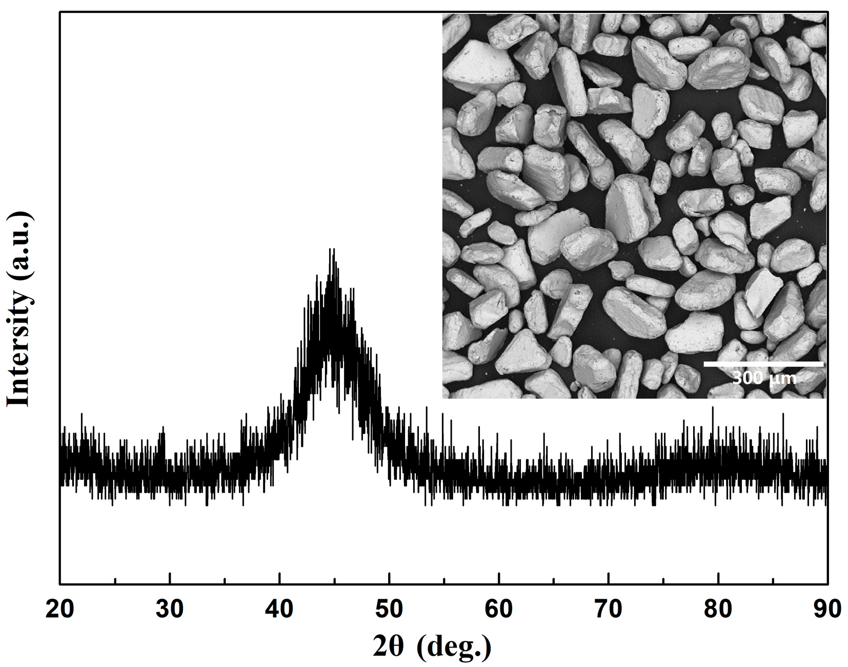
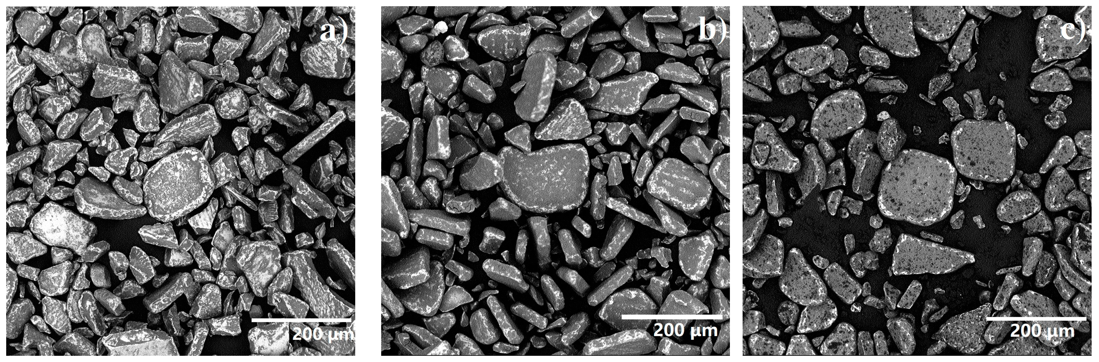
3.1. Microstructure of Amorphous Powders

Figure 1 displays the representative XRD pattern of the ball-milling-crushed Fe78Si9B13 amorphous powders. A broad diffuse peak at around 2θ = 45°, without any distinct diffraction peaks, could only be seen for the powders, which validated the formation of an amorphous structure. The inset of Figure 1 shows the morphology of the ball-milling-crushed Fe78Si9B13 amorphous powders with the particle size ranging up to 125 μm. The powders were in the shape of a polygon with smooth edges, which was beneficial to the uniform insulation coating, thereby reducing the eddy current loss between the powders.

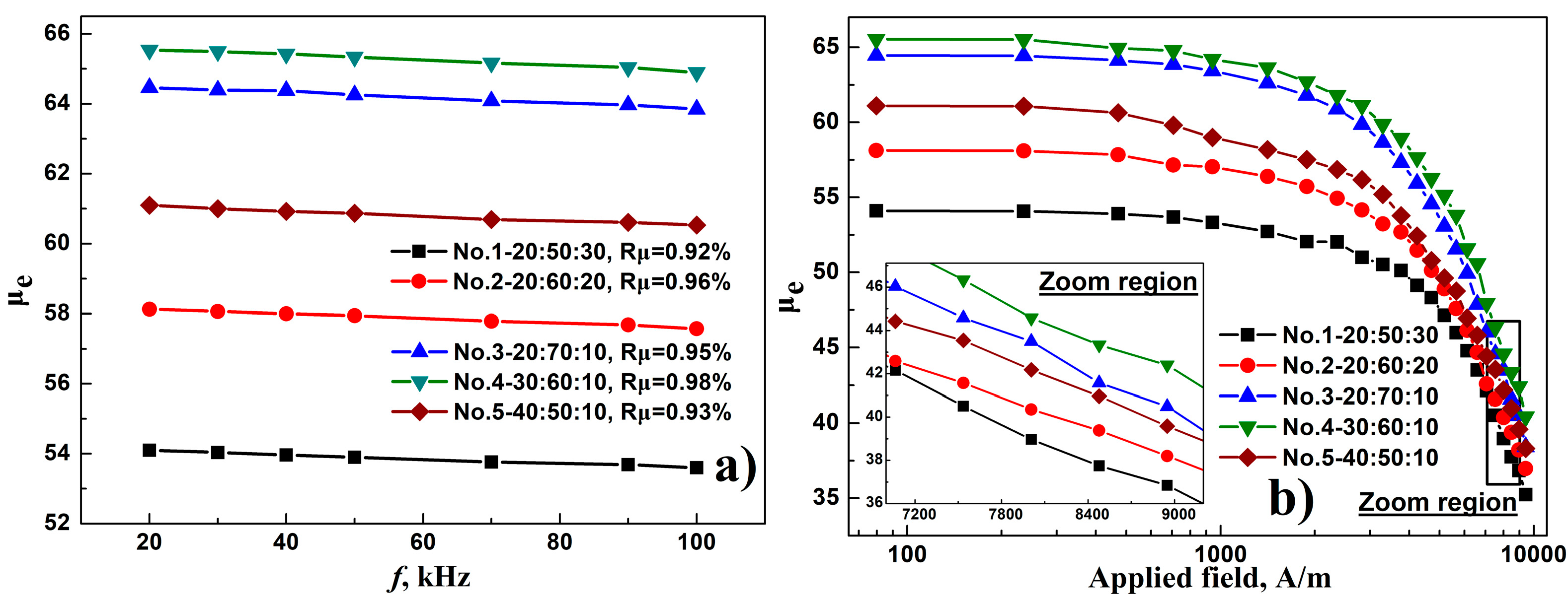
3.2. Particle Size Distribution

Table 1 lists the characterization of particle size distribution, green compact density, ρ, effective permeability, μe, and core loss, Pc, for the AMPCs with different matching ratios (mass percent) of P1/P2/P3%. In this table, D10, D25, D50, D75, and D90 represent the specific particle size at which the cumulative frequency showed 10%, 25%, 50%, 75%, and 90%, respectively. The green compact density of the AMPCs was analyzed by the principle of Archimedes. Figure 2 displays the morphology of the AMPCs with different matching ratios. Figure 3 displays the matching ratio dependence of the frequency characteristic and DC-bias performance. We observed the following points. (1) The attenuation rate of μe, Rμ, in the frequency band of 20–100 kHz for the AMPCs was 0.92–0.98%. It was indicated that the AMPCs with different matching ratios, given in Table 1, exhibited good constant magnetic properties with the frequency. (2) The circumferential crack was observed at the outer surface of the AMPCs when the mass ratio of the P1 powders was greater than 30 wt.%. This could be due to the increasing number of large pores induced by the increase of the coarse particles (P1 powders with the particle size distribution of 140–170 mesh), which was detrimental to the formability enhancement of the AMPCs [28]. (3) The AMPCs’ green compact density, ρ, the effective permeability, μe, and the residual effective permeability at the applied magnetizing field of 7.96 kA/m, μe@7.96 kA/m, increased first and then decreased with the increasing size of D50, and exhibited a maximum ρ of 5.66 g/cm3 and a maximum μe of 65.54, as the mass ratios of the P1%/P2%/P3% powders were 20:70:10 and 30:60:10, respectively. The AMPCs’ μe can be calculated using the following equation:
μ e = L s l e μ 0 N 2 A e ,
where Ls, Ae and le are the inductance, the cross-section area, and the mean flux density path length of the ring sample cores, respectively. N is the total number of coil turns and μ0 is the free space permeability.
It was seen that the magnitude of the μe strongly depended on the number and size of pores in the AMPCs according to the le in Equation (1). For the AMPCs of numbers 3, 2, and 1, as the mass ratio of fine powders (P3) increased from 10 wt.% to 30 wt.%, the interface between the magnetic particles and the specific surface area of the powders subsequently increased, followed by an increasing number of the pores. Thus, the μe and ρ gradually decrease from 64.54 to 53.10, and from 5.66 g/cm3 to 5.55 g/cm3. For the AMPCs of numbers 3, 4, and 5, the ratio of the coarse powders (P1) increased from 20 wt.% to 40 wt.%, which would lead to the increasing number of large pores in the AMPCs [28]. Accordingly, the ρ gradually decreased from 5.66 g/cm3 to 5.52 g/cm3. The μe, however, increased first and then decreased. A small increment of 1.08 for μe was observed as the mass ratio of P1%/P2%/P3% changed from 20:70:10 to 30:60:10, which could be attributed to the increase of the average particle size for AMPCs [29].
(4) It is known that the eddy current loss is dominant for the core loss in the high-frequency range. The eddy current loss is inversely proportional to the electrical resistivity but proportional to the square of particle size [30]. It was seen that the Pc gradually increased from 315.2 mW/cm3 to 409.7 mW/cm3, at 50 kHz for Bm = 0.1 T, as the size of D50 increased from 66.5 μm to 90.2 μm. Moreover, it was also shown that a small increment of 24.31 mW/cm3 for the Pc was observed as the ratio of the P3 powders decreased from 30 wt.% to 10 wt.%, with a constant ratio of 20 wt.% for the P1 powder. Based on the discussion above, the matching ratio of 20:70:10 for P1%/P2%/P3% was adopted as a reasonable process parameter for the subsequent fabrication of the AMPCs, because of its higher μe, relatively lower Pc, and being easier to shape, compared with the other matching ratios.

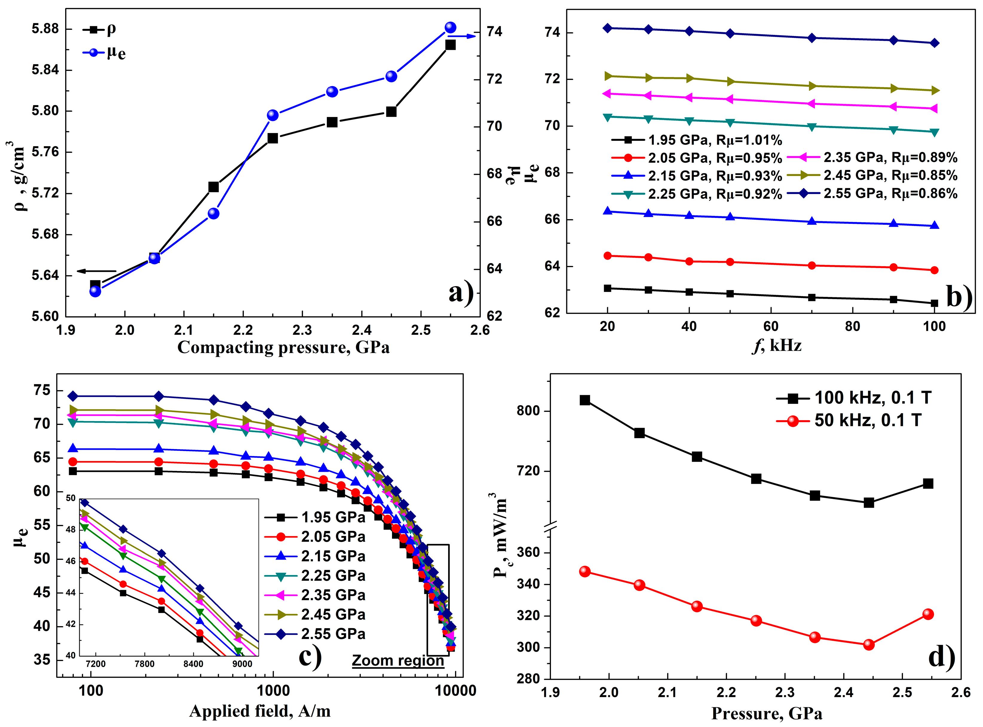
3.3. Molding Pressure

Figure 4 shows the SEM micrographs of AMPCs’ cross-sections under three different molding pressures of 1.95 GPa, 2.15 GPa, and 2.35 GPa, wherein the matching ratio of P1%/P2%/P3% for the AMPCs was 20:70:10. Figure 5 displays the dependence of the molding pressure on the compact density, the effective permeability, the frequency characteristic, the DC-bias performance, and the core loss for the AMPCs. It was observed that the microstructure of the AMPCs’ cross-section consisted of coated powders and pores. The pores showed a three-dimensional network. With the increase of the molding pressure, the pore volume and its ratio gradually reduced. Accordingly, the AMPCs’ green compact density, ρ, the effective permeability, μe, and the residual effective permeability at an applied field of 7.96 kA/m, μe@7.96 kA/m, increased from 5.63 g/cm3 to 5.86 g/cm3, from 62.37 to 73.91, and from 42.95 to 46.53, as the molding pressure increased from 1.95 GPa to 2.55 GPa, respectively. The MPCs’ Pc decreased first and then increased with the increasing molding pressure, and exhibited a minimum value of 301.92 mW/cm3 (at 50 kHz for Bm = 0.1 T) at a molding pressure of 2.45 GPa. The attenuation ratio of μe in the frequency band of 20–100 kHz, Rμ, slowly went down from 1.02% to 0.85% with the increasing molding pressure. This was beneficial to the frequency characteristic improvement of the AMPCs.
Moreover, it was seen from Figure 5a,d that both the μe and Pc rapidly increased as the molding pressure surpassed 2.45 GPa. This could be contributed to the damage of the coated insulation material and the increasing residual stress caused by greater molding pressure. When the molding pressure was lower than 2.45 GPa, the increasing process of μe could be divided into two different stages: The initial fast increasing stage (1.95–2.25 GPa), and the subsequent stably increasing stage (2.25–2.45 GPa). It was also seen from Figure 5d that a small increment of 4.70 mW/cm3 for the core loss was observed as the molding pressure decreased from 2.45 GPa to 2.35 GPa. Thus, it was concluded that the molding pressure range of 2.35–2.45 GPa was reasonable for the AMPCs’ fabrication.

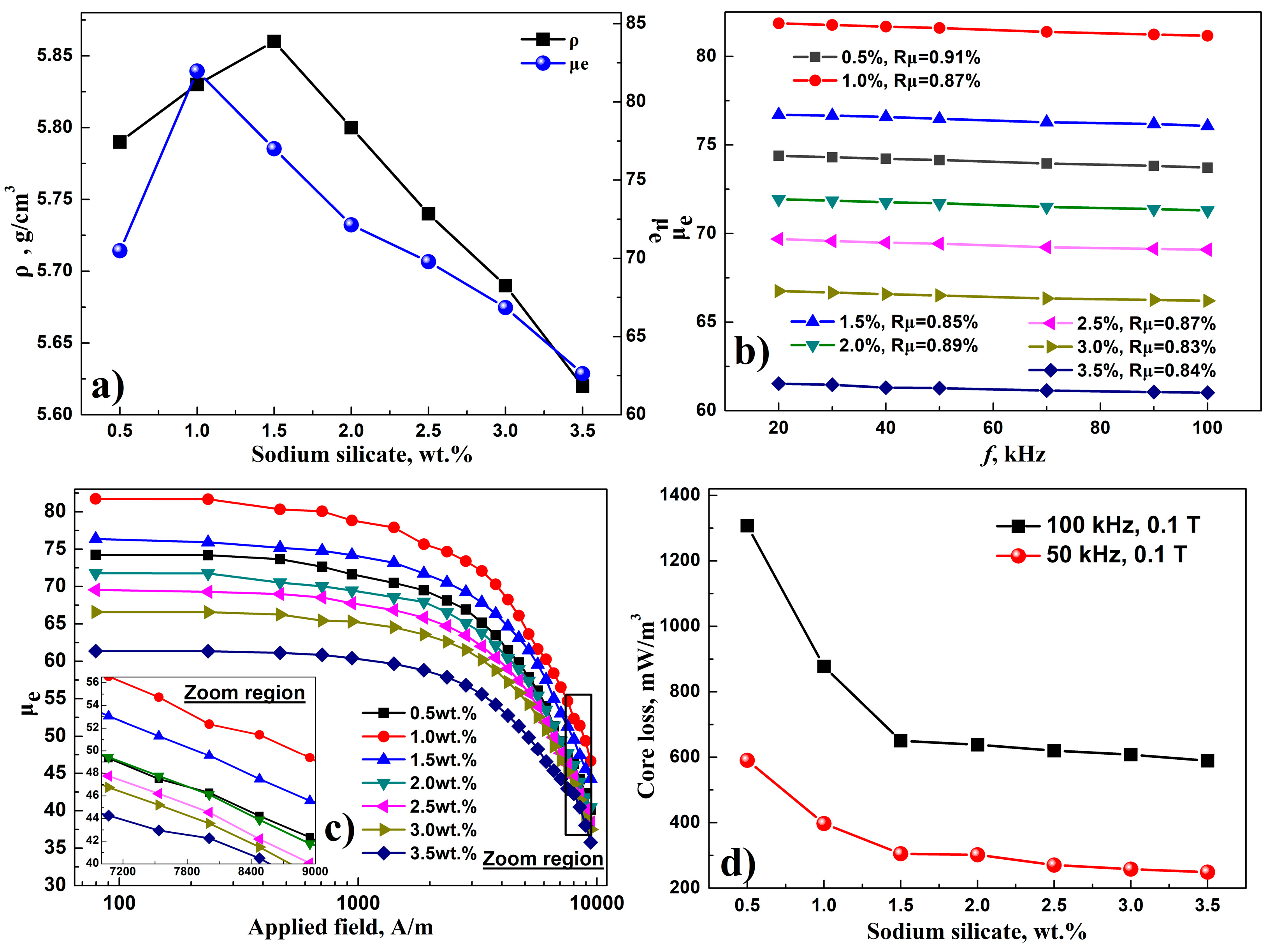
3.4. Insulating Material Content

Figure 6 shows the SEM micrographs of the coated magnetic powders with three different coating agent (sodium silicate) contents of 0.5 wt.%, 1.0 wt.% and 2.0 wt.%. Figure 7 displays the dependence of the sodium silicate content on the compact density, the effective permeability, the frequency characteristic, the DC-bias performance, and the core loss for the AMPCs with a P1%/P2%/P3% ratio of 20:70:10 and a molding pressure of 2.45 GPa. It was seen that the increase of the coating agent content was beneficial to obtaining an even electro-insulating layer on the surface of the magnetic powders. The attenuation ratio of μe, Rμ, in the frequency band of 20–100 kHz was in the range of 0.83%–0.91%. That meant that the AMPCs with different sodium silicate contents all exhibited good frequency stabilities of effective permeability. The AMPCs’ core loss, Pc, as shown in the Figure 7d, gradually decreased from 590.54 mW/cm3 to 248.93 mW/cm3, at 50 kHz for Bm = 0.1 T, with an increasing content of sodium silicate from 0.5 wt.% to 3.5 wt.%, due to the improving insulation effect for the AMPCs.
As seen from Figure 7a–c, the AMPCs’ ρ, μe, and μe@7.96 kA/m initially increased, but was followed by a decline with the increasing content of sodium silicate. Within the content range of 0.5 wt.%–1.5 wt.%, the ρ increased with the increase of the sodium silicate content. This was due to the lubrication film on the particle surface, generated by the coating agent, which can enhance the mobility of the particles during the compacting process [27,29]. For the μe, too low content of sodium silicate (0.5 wt.%, seen in Figure 6a) would result in the increased number of pores, due to the poor bonding effect for the particles in the AMPCs. Thus, a μe of 70.49 was observed. As the sodium silicate content increased to 1.0 wt.%, the uneven coating layer on the powder surface—as shown in the Figure 6b—would cause the poor insulation for particles in the AMPCs, and in turn, the μe climbed to 81.87. With the improved insulation effect for particles, the μe decreased to 77.01 as the sodium silicate content increased to 1.5 wt.%. Moreover, it was also seen that both the ρ and μe gradually decreased when the sodium silicate content was greater than 1.5 wt.%, due to the increasing ratio of non-magnetic material (coating agent) in the AMPCs. Therefore, the sodium silicate additive amount of 1.5 wt.% was proposed for the AMPCs’ fabrication with a P1%/P2%/P3% mass ratio of 20:70:10 and a molding pressure of 2.45 GPa. And then, an excellent comprehensive soft magnetic property could be obtained as follows: μe = 77.01, 0.85% < Rμ, μe (at a bias field of 7.96 kA/m) = 49.57, Pc (at 50 kHz for Bm = 0.1 T) = 305.23 mW/cm3, and Pc (at 100 kHz for Bm = 0.1 T) = 650.46 mW/cm3.

4. Conclusions

The comprehensive soft magnetic properties of the Fe78Si9B13 AMPCs have been enhanced by the coordinated adjustments of the particle size distribution, the compacting pressure, and the coating agent content in the industrial condition. The optimal magnetic properties of the Fe78Si9B13 AMPCs can be obtained when the technological parameters are as follows: The matching ratio of P1%/P2%/P3% is 20:70:10 in mass percent, the molding pressure is in the range of 2.35–2.45 GPa, and the additive amount of sodium silicate is 1.5 wt.%. As compared to the original scheme (the P1%/P2%/P3% mass ratio in 20:60:20, the molding pressure in 2.05 GPa, and the sodium silicate content in 2.0 wt.%), the AMPCs’ compact density, ρ, the effective permeability, μe, and the residual effective permeability at 7.96 kA/m, μe@7.96 kA/m, increased from 5.61 g/cm3 to 5.86 g/cm3, from 58.13 to 77.01, and from 40.36 to 49.57, respectively, while the core loss reduced from 380.85 mW/cm3 to 335.23 mW/cm3 (at 50 kHz for Bm = 0.1 T).

Author Contributions

H.S. and W.C. conceived and designed the experiments; C.W. and J.L. performed the experiments and analyzed the data; H.S. wrote the paper.

Funding

This research was funded by the National Natural Science Foundation of China (Grant No. 51704078), the Province Natural Science Fund of Guangdong (Grant No. 2017A030313312), the university key platform funding projects of Guangdong education department (Grant No. gg041002), the engineering technology research center project of Foshan City (Grant No. 20172010018) and the talent research start-up program of Foshan University (Grant No. gg040942).

Conflicts of Interest

The authors declare no conflict of interest.

References

  1. Shokrollahi, H.; Janghorban, K. Soft magnetic composite materials (SMCs). J. Mater. Process. Technol. 2007, 189, 1–12. [Google Scholar] [CrossRef]
  2. Valchev, V.C.; Todorova, T.P.; Bossche, V.A. Comparison and design of DC chokes based on different magnetic materials. In Proceedings of the 2017 XXVI International Scientific Conference Electronics (ET), Sozopol, Bulgaria, 13–15 September 2017; IEEE: Piscataway, NJ, USA, 2017. [Google Scholar]
  3. Leary, A.M.; Ohodnicki, P.R.; Mchenry, M.E. Soft Magnetic Materials in High-Frequency, High-Power Conversion Applications. JOM 2012, 64, 772–781. [Google Scholar] [CrossRef]
  4. Sugimura, K.; Shibamoto, D.; Yabu, N.; Yamamoto, T.; Sonehara, M.; Sato, T.; Mizuno, T.; Mizusaki, H. Surface-Oxidized Amorphous Alloy Powder/Epoxy-Resin Composite Bulk Magnetic Core and Its Application to Megahertz Switching LLC Resonant Converter. IEEE. T. Mag. 2017, 53, 1–6. [Google Scholar] [CrossRef]
  5. Zhang, L.; Li, D.; Lu, Z.; Liu, T.; Guo, F.; Liu, K.; Wang, J.; Zhou, S. Novel Fe-based amorphous magnetic powder cores with ultra-low core losses. Sci. China. Technol. Sci. 2010, 53, 1290–1293. [Google Scholar] [CrossRef]
  6. Salmi, W.A.; Gyawali, P.; Dahal, B.; Pegg, I.L.; Philip, J. Core-shell FeNi-NixFe3-xO4 nanowires. J. Vac. Sci. Technol. B 2015, 33, 040604. [Google Scholar] [CrossRef]
  7. Otsuka, I.; Kadomura, T.; Ishiyama, K.; Yagi, K. Magnetic Properties of Fe-Based Amorphous Powder Cores with High Magnetic Flux Density. IEEE T. Mag. 2009, 45, 4294–4297. [Google Scholar] [CrossRef]
  8. Huang, C.; Liu, T.; Wang, X.; Lu, C.; Li, D.; Lu, Z. Magnetic properties of Fe82Si2B14C2 amorphous powder cores with low core loss and high magnetic flux density. Powder Metall. 2014, 57, 41–44. [Google Scholar] [CrossRef]
  9. Wei, D.; Wang, X.; Nie, Y.; Feng, Z.; Chen, Y.; Harris, V.G. Low loss Sendust powder cores comprised of particles coated by sodium salt insulating layer. J. Appl. Phys. 2015, 117, 17A921. [Google Scholar] [CrossRef]
  10. Liu, M.; Huang, K.; Liu, L.; Li, T.; Cai, P.; Dong, Y.; Wang, X. Fabrication and magnetic properties of novel Fe-based amorphous powder and corresponding powder cores. J. Mater. Sci-Mater. El. 2018, 29, 6092–6097. [Google Scholar] [CrossRef]
  11. Guo, J.; Dong, Y.; Man, Q.; Li, Q.; Chang, C.; Wang, X.; Li, R. Fabrication of FeSiBPNb amorphous powder cores with high DC-bias and excellent soft magnetic properties. J. Magn. Magn. Mater. 2016, 401, 432–435. [Google Scholar] [CrossRef]
  12. Li, X.; Dong, Y.; Liu, M.; Chang, C.; Wang, X. New Fe-based amorphous soft magnetic composites with significant enhancement of magnetic properties by compositing with nano-(NiZn)Fe2O4. J. Alloys Compd. 2017, 696, 1323–1328. [Google Scholar] [CrossRef]
  13. Zhao, G.; Wu, C.; Yan, M. Fabrication and growth mechanism of iron oxide insulation matrix for Fe soft magnetic composites with high permeability and low core loss. J. Alloys Compd. 2017, 710, 138–143. [Google Scholar] [CrossRef]
  14. Xiao, L.; Sun, Y.; Ding, C.; Yang, L.; Yu, L. Annealing effects on magnetic properties and strength of organic-silicon epoxy resin-coated soft magnetic composites. J. Mech. Eng. Sci. 2014, 228, 2049–2058. [Google Scholar] [CrossRef]
  15. Kollar, P.; Bircakova, Z.; Fuezer, J.; Bures, R.; Faberova, M. Power loss separation in Fe-based composite materials. J. Magn. Magn. Mater. 2013, 327, 146–150. [Google Scholar] [CrossRef]
  16. Peng, Y.; Yi, Y.; Li, L.; Yi, J.; Nie, J.; Bao, C. Iron-based soft magnetic composites with Al2O3 insulation coating produced using sol–gel method. Mater. Des. 2016, 109, 390–395. [Google Scholar] [CrossRef]
  17. Wang, J.; Fan, X.; Wu, Z.; Li, G. Intergranular insulated Fe/SiO2 soft magnetic composite for decreased core loss. Adv. Powder. Technol. 2016, 27, 1189–1194. [Google Scholar] [CrossRef]
  18. Xie, D.; Lin, K.; Lin, S. Effects of processed parameters on the magnetic performance of a powder magnetic core. J. Magn. Magn. Mater. 2014, 353, 34–40. [Google Scholar] [CrossRef]
  19. Streckova, M.; Hadraba, H.; Bures, R.; Faberova, M.; Roupcova, P.; Kubena, I.; Medvecky, L.; Girman, V.; Kollar, P.; Fuzer, J.; et al. Chemical synthesis of nickel ferrite spinel designed as an insulating bilayer coating on ferromagnetic particles. Surf. Coat. Technol. 2015, 270, 66–76. [Google Scholar] [CrossRef]
  20. Xie, Y.; Yan, P.; Yan, B. Enhanced Soft Magnetic Properties of Iron-Based Powder Cores with Co-Existence of Fe3O4–MnZnFe2O4 Nanoparticles. Metals 2018, 8, 702. [Google Scholar] [CrossRef]
  21. Li, B.; Zheng, Z.; Yu, H.; Zeng, D. Improved permeability of Fe based amorphous magnetic powder cores by adding Permalloy. J. Magn. Magn. Mater. 2017, 438, 138–143. [Google Scholar] [CrossRef]
  22. Yagi, M.; Endo, I.; Otsuka, I.; Yamamoto, H.; Okuno, R.; Koshimoto, H.; Shintani, A. Magnetic properties of Fe-based amorphous powder cores produced by a hot-pressing method. J. Magn. Magn. Mater. 2000, 215–216, 284–287. [Google Scholar] [CrossRef]
  23. Zheng, Y.; Wang, Y.; Xia, G. Amorphous soft magnetic composite-cores with various orientations of the powder-flakes. J. Magn. Magn. Mater. 2015, 396, 97–101. [Google Scholar] [CrossRef]
  24. Li, Z.; Dong, Y.; Li, F.; Chang, C.; Wang, X.; Li, R. Fe78Si9B13 amorphous powder core with improved magnetic properties. J. Mater. Sci-Mater. El. 2017, 28, 1180–1185. [Google Scholar] [CrossRef]
  25. Li, Z.; Dong, Y.; Pauly, S.; Chang, C.; Wei, R.; Li, F.; Wang, X. Enhanced soft magnetic properties of Fe-based amorphous powder cores by longitude magnetic field annealing. J. Alloys Compd. 2017, 706, 1–6. [Google Scholar] [CrossRef]
  26. Dong, Y.; Li, Z.; Liu, M.; Chang, C.; Li, F.; Wang, X. The effects of field annealing on the magnetic properties of FeSiB amorphous powder cores. Mater. Res. Bull. 2017, 96, 160–163. [Google Scholar] [CrossRef]
  27. Liu, H.; Su, H.; Geng, W.; Sun, Z.; Song, T.; Tong, X.; Zou, Z.; Wu, Y.; Du, Y. Effect of Particle Size Distribution on the Magnetic Properties of Fe-Si-Al Powder Core. J. Supercond. Nov. Magn. 2016, 29, 463–468. [Google Scholar] [CrossRef]
  28. Bai, R.; Zhu, Z.; Zhao, H.; Mao, S.; Zhong, Q. The percolation effect and optimization of soft magnetic properties of FeSiAl magnetic powder cores. J. Magn. Magn. Mater. 2017, 433, 285–291. [Google Scholar] [CrossRef]
  29. Taghvaei, A.; Shokrollahi, H.; Ghaffari, M.; Janghorban, K. Influence of particle size and compaction pressure on the magnetic properties of iron-phenolic soft magnetic composites. J. Phys. Chem. Solids. 2010, 71, 7–11. [Google Scholar] [CrossRef]
  30. Taghvaei, A.; Shokrollahi, H.; Janghorban, K.; Abiri, H. Eddy current and total power loss separation in the iron–phosphate–polyepoxy soft magnetic composites. Mater. Des. 2009, 30, 3989–3995. [Google Scholar] [CrossRef]
Figure 1. X-ray diffraction (XRD) patterns of the ball-milling-crushed Fe78Si9B13 amorphous powders, the inset shows the scanning electron microscope (SEM) micrograph of the powders
Metals 09 00381 g001
Figure 2. Morphology of the amorphous magnetic powder cores (AMPCs) with different matching ratios of P1%/P2%/P3%.
Metals 09 00381 g002
Figure 3. Dependence of matching ratio on frequency characteristic (a) and direct current (DC) bias performance (b).
Metals 09 00381 g003
Figure 4. SEM micrographs of AMPCs’ cross-sections under different molding pressures, (a) 1.95 GPa, (b) 2.15 GPa, and (c) 2.35 GPa.
Metals 09 00381 g004
Figure 5. Dependence of the molding pressure on the compact density, the effective permeability (a), the frequency characteristic (b), the DC-bias performance (c), and the core loss (d) for the AMPCs.
Metals 09 00381 g005
Figure 6. SEM micrographs of the coated magnetic powders with three different sodium silicate contents of 0.5 wt.% (a), 1.0 wt.% (b) and 2.0 wt.% (c).
Metals 09 00381 g006
Figure 7. Dependence of the sodium silicate content on the compact density, the effective permeability (a), the frequency characteristic (b), the DC-bias performance (c), and the core loss (d) for the AMPCs.
Metals 09 00381 g007
Table 1. Characterization of particle size distribution, green compact density, effective permeability, and core loss for the amorphous magnetic powder cores (AMPCs) with different matching ratios of P1%/P2%/P3%.
Matching Ratio (P1%:P2%:P3%)Characterization of Particle Size Distributionρ, g/cm3μePc@50 kHz, 0.1 T, mW/cm3
D10, μmD25, μmD50, μmD75, μmD90, μm
No. 1—20:50:3044.3050.5066.5085.60114.405.5553.10315.23
No. 2—20:60:2046.8057.4069.9089.40119.805.6158.13330.85
No. 3—20:70:1049.5066.7074.1096.30132.305.6664.46339.54
No. 4—30:60:1051.7070.2081.10110.00141.205.6365.54374.28
No. 5—40:50:1053.1075.3090.20123.40156.405.5261.10409.76

