Abstract
In recent years, it has been found that the service life of cemented carbide shield machine tools used in uneven soft and hard strata is substantially reduced in engineering practice. The study found that thermal stress is the main reason for the failure of cemented carbide shield tunneling tools when shield tunneling is carried out in uneven soft and hard soil. To maintain the hardness of cemented carbide, improving the thermal conductivity of the shield machine tool is of great importance for prolonging its service life and reducing engineering costs. In this study, graphene and carbon nanotubes were mixed with WC–Co powder and sintered by spark plasma sintering (SPS). The morphology was observed by scanning electron microscopy (SEM) and energy dispersive X-ray spectroscopy (EDS). The Rockwell hardness, bending strength, and thermal conductivity of the samples were tested. The results show that adding a small amount of graphene or carbon nanotubes could increase the bending strength of the cemented carbide by approximately 50%, while keeping the hardness of the cemented carbide constant. The thermal conductivity of the cemented carbide could be increased by 10% with the addition of 0.12 wt % graphene alone.
1. Introduction
Cemented carbide has sufficient hardness, wear resistance, and toughness to avoid brittle fracture [1]. It has been applied very successfully in shield cutting tools. However, when shield tunneling in uneven soft and hard underlying soil, thermal stress and other factors substantially reduce the service life of cutting tools. The average working temperature of the cutter in the shield machine is 500 °C, sometimes 1500 °C in extreme circumstances [2,3].
Current research shows that the main failure modes of cemented carbide cutters in shield machines are fracture and wear. The reason for failure is that, under the simultaneous action of mechanical stress and thermal stress, microcracks are formed and then propagate until the failure of the cemented carbide tools occurs [4,5]. Mikado et al. [6] investigated the fatigue crack growth (FCG) behavior of short surface cracks in a fine-grained cemented carbide with a length of less than 1 mm and found that the FCG was along the brittle WC/WC interface in a low maximum stress intensity factor. Wu et al. [7] conducted experiment on direct micro milling of cemented carbide with a polycrystalline diamond (PCD) micro end mill, whose research suggested that the tool wear process presented microchipping on the cutting edge and exfoliating on the rake face in the early stage, and then presented severe abrasive and adhesive wear on the bottom face in the following stage. Gallardo et al. [8] applied the electrical resistance sintering (ERS) technology to obtain WC10Co parts. The relative density values, measured on different zones of an axial section of the 100 MPa compact, had a standard deviation lower than 1%. Sribalaji et al. [9] suggested that thermal stress led to tool cracking, which would lead to tool propagation and fracture, resulting in a sharp decline in the service life of cemented carbide. It was also proved by experiments that tool life was significantly affected by the region of thermal strain and the number of thermal cycles during intermittent cutting. Beste et al. [10] prepared slices of the bit surface for analysis using focused ion beam and electron beam thinning. The samples of the bit surface after drilling were analyzed with a transmission electron microscope (TEM). The Co bonding phase was confirmed to melt first at high temperature, while WC did not. The results showed that the weakness of cemented carbide tools may be mainly due to the partial melting or softening of the bonding phase owing to an insufficient melting point and insufficient thermal conductivity of the bonding phase at high temperature. The cemented carbide then failed as a result of thermal stress [11].
Therefore, if a method could be found to improve the thermal conductivity while maintaining the hardness of the cemented carbide, the temperature of the tool would be greatly reduced, and the service life of the tool would be increased. Graphene and carbon nanotubes have attracted much attention in recent years due to their extremely high thermal conductivity and strength. The thermal conductivity of carbon nanotubes and graphene is around 3000 W/(m·K) [12] and 5300 W/(m·K) [13], respectively. We attempted to improve the performance of cemented carbide in high temperature using the excellent properties of graphene and carbon nanotubes. If graphene and carbon nanotubes can be evenly dispersed in the Co phase, then the dispersed graphene and carbon nanotubes could form channels with effective high thermal conductivity. Moreover, the second phase dispersion strengthening principle could be used to improve the fracture resistance of the cemented carbide matrix to ensure that the cemented carbide retains a high hardness while improving the thermal conductivity. In the field of ceramics and metals, Zhang, Huang, and others [14,15,16] added nano-phases (carbon nanotubes and nano-Al2O3) to cemented carbides, which strengthened and toughened the Co phase. Yan et al. [17] doped graphene nanosheets into an aluminum and aluminum alloy matrix that could significantly improve the mechanical properties of the aluminum matrix, such as the tensile strength, yield strength, bending strength, and hardness. Zhao’s [18] article illustrated the synergistic effect of graphene and carbon nanotubes. Boccarusso et al. [19] added different mass fractions of Cr3C2 in the range of 0–3 wt %, which could increase hardness, reduce grain size considerably, and enhance the wear performance of cemented carbides. Fabijanić et al. [20] found that the addition of 0.45% Cr3C2 in WC contributed to microstructure homogeneity and reduced discontinuous and continuous grain growth, which increased Vickers hardness by approximately 70 HV and fracture toughness by approximately 0.15 MN/m3/2. Konyashin et al. [21] observed the phenomenon of precipitating fine grains of WC and η-phase in the interface region of a binder model alloy with low carbon content. Armstrong [22] found that the mean free path dimensions of Co binder were important in affecting the composite material toughness properties and fracturing behavior of internal thermal micro-stresses. However, there is no research on the effects of graphene and carbon nanotubes on the thermal conductivity of WC–Co cemented carbide. In this paper, WC–Co cemented carbide with different amounts of graphene and carbon nanotubes was prepared by a powder metallurgy process. The effects of the graphene and carbon nanotubes on the thermal conductivity, hardness, and bending strength were investigated.
2. Materials and Methods
2.1. Materials
Commercially available graphene and carbon nanotubes were used from XF Nano Inc. (Nanjing, China) Commercially available WC powder and Co powder were used from Beijing DK nano technology Co. LTD (Beijing, China). The primary tungsten carbide powder used in this study had a particle size of 5 µm and a purity of 99.9%. The nano-cobalt powder had a particle size of 50 nm, a purity of 99.9%, a specific surface area of 40–60 m2/g, and a density of 8.9 g/cm3. The single-walled carbon nanotubes (SWCNTs) had a thickness of 0.8 nm, a diameter of 0.5–2 µm, a purity of 99%, and a single-layer rate of 80%. The specific surface area of monolayer graphene is greater than 380 m2/g, and the purity is greater than 90%. The experimental specimens were sintered by spark plasma sintering (SPS) [23] and the composition of the test samples are shown in Table 1. The samples were sintered at 1200 °C for 10 min at a pressure of 80 MPa. The samples were heated to 650 °C within 5 min, then from 650 to 1000 °C and from 1000 to 1200 °C using a heating rate of 80 and 60 K/min.

Table 1.
The composition of the test samples.
A planetary ball mill was used to mix the powder. According to the force analysis and calculation of the ball in the planetary ball mill, it was concluded that, when the radius of rotating motion was 0.0325 m, the rotational speed set below 166 r/min would not result in centrifugation. The ball milling speed was 110 r/min, and the milling time was 4 h. Ethanol was used as the medium [24]. After powder mixing and dispersing, the mixed powder was dried in a vacuum drying furnace. The dried powder was poured into a high-strength graphite jig. Sintered cylindrical samples with a diameter of 20 mm were prepared by SPS equipment. They were cut into blocks and strips using a wire cutting method. The size of the block was 10 × 10 × 3 mm, and the size of the strip was 19 × 2 × 3 mm. The block sample was used to measure the thermal diffusivity and hardness, and the strip sample was used to measure the bending strength and then for morphology analysis. Because of the high hardness of the sample, the upper and lower surfaces of the sample were burnished with diamond abrasive discs.
2.2. Testing of WC–Co Cemented Carbide Samples
Because of the small size of the sintered sample in this experiment, the thermal conductivity cannot be measured directly, but it could be calculated by measuring the thermal diffusivity and other parameters. Therefore, a TC-7000H laser thermal constant tester (SINKU-RIKO.INC., Yokohama, Japan) was used to measure the thermal diffusivity of WC–Co cemented carbide samples by a laser method. The specific heat capacity of WC–Co cemented carbide samples was measured via DSC8500 differential scanning calorimetry (Perkin Elmer, Waltham, MA, USA). Quality was measured with an electronic scale, and volume was measured with the Archimedes method. The bending strength of the sample was measured by a three-point test using MTS E45.105 (Yinfei Electronic Technology Co., Ltd., Shenzhen, China). The hardness of the sample was measured by a Rockwell hardness tester. The morphology of the samples was observed by a MIRA 3 LMH field emission scanning electron microscope (TESCAN CHINA LTD., Shanghai, China), and energy dispersive spectroscopy (EDS) was carried out with an Aztec Energy Standard X-MaxN 20 instrument (Oxford Instruments, Shanghai, China). The Vickers hardness of WC–Co cemented carbide was measured with an HV-120 Vickers hardness tester (Laizhou Testing Machine Factory Co., Ltd., Laizhou, China). The X-ray diffraction of the samples was carried out with a Bruker Axs D8 Advance (Bruker AXS, Karlsruhe, Germany).
3. Results and Discussion
3.1. Thermal Conductivity of WC–Co Cemented Carbide
Thermal diffusivity of WC–Co cemented carbide samples were tested as shown in Table 2. After the thermal diffusivity was tested, the following data were obtained at 500 °C. As shown in Table 3, the volume and mass were determined for each sample, and the average density of the sample group was calculated.
Table 2.
Thermal diffusivity of WC–Co cemented carbide.
Table 3.
Density of WC–Co cemented carbide.
The volume of the sample was measured by the Archimedes drainage method, the mass of the sample was weighed by electronic balance, and the density of the sample was calculated, which represents the porosity of the sample to a certain extent. The difference in specific heat capacity between the three groups of samples was very small. Because of equipment limitations, the specific heat capacity data could be measured only between room temperature and 400 °C. Specific heat capacity data between 30 and 400 °C was shown in Figure 1. The specific heat capacity data at 500 °C could be estimated from the linear relationship between the specific heat capacity and temperature change. The specific heat capacities of the three groups of samples were estimated to be approximately 0.23 J/(g·°C) at 500 °C by linear fitting.
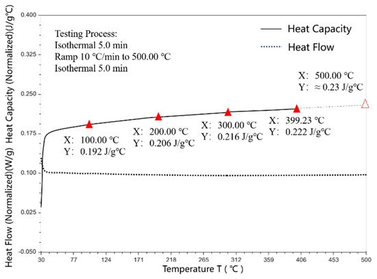
Figure 1.
Specific heat capacity data between 30 and 400 °C.
By referring to the research of Chen et al. [25] and Wang et al. [26] on the theoretical calculation of the equivalent thermal conductivity of composite materials, thermal conductivity can be calculated by the following formula:
where λ is the thermal conductivity, α is the thermal diffusivity, Cp = 0.23 is the heat capacity, and ρ is the density. Thermal conductivity of WC–Co cemented carbide samples were shown in Table 4.
λ = αCpρ
Table 4.
Thermal conductivity of WC–Co cemented carbide.
Figure 2 shows that the thermal conductivity of the samples increased to varying degrees after adding graphene and carbon nanotubes. Compared with that of the original samples, the thermal conductivity of the cemented carbide samples with 0.06 wt % carbon nanotubes and 0.06 wt % graphene increased by 2.6%. The thermal conductivity of the cemented carbide samples with 0.12 wt % carbon nanotubes was 3.8% higher than that of the original samples, and the thermal conductivity of the cemented carbide samples with 0.12 wt % graphene was 9.9% higher than that of the original samples. It is noteworthy that the thermal conductivity of the samples with the addition of 0.12 wt % graphene increased significantly by nearly 10%. The results showed that graphene, compared to carbon nanotubes, has a more beneficial effect on the thermal conductivity of cemented carbide.
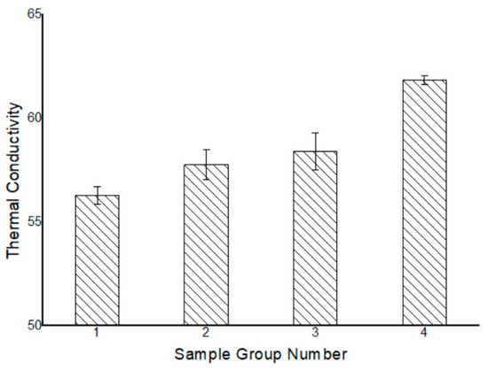
Figure 2.
Thermal conductivity of WC–Co cemented carbide.
In order to evaluate the effect, the results were compared with the value predicted by the Maxwell–Eucken (ME) equation. The well-known Maxwell–Eucken equation is frequently used to reflect the corresponding relationship between the equivalent thermal conductivity and volume fraction of the composites [27]:
where λc, λm, and λf, are thermal conductivities of composite, matrix, and filler, respectively, and Vf is the volume fraction of filler. To explore the special effect of graphene and carbon nanotubes on improving thermal conductivity, the thermal conductivity was calculated according to the ME equation, in which only graphite was added and in which the mass fraction of graphite was 0.12%. Agari found that the true thermal conductivity agreed fairly well with the predicted results according to the ME equation if the volume fraction of graphite was less than 10% [28]. When the quality fraction of graphite is 0.12%, its volume fraction in WC–Co cemented carbide can be calculated. The density of WC, Co, and graphite is 15.63, 8.9 and 2.25 g/cm3, respectively. By taking their densities into account, the volume fraction of graphite can be calculated as 0.79%. The conventional thermal conductivity of graphite λf was 151 W/(m·K), the conventional thermal conductivity of original samples λm was 56.28 W/(m·K), and Vf was 0.79%. The λc could then be calculated to be 56.76 W/(m·K), which was only 0.85% higher than that of the original samples. Compared with this, the 10% increase by adding 0.12 wt % graphene could show that graphene has an effectively beneficial effect on thermal conductivity.
This may be due to the following factors. First, the specific surface area of graphene and carbon nanotubes is large. Although the mass fraction was only 0.12%, the actual volume fraction may be higher. Second, some types of graphene distributions could bridge the interface between WC and Co and reduce the thermal resistance. According to the theory of contact thermal resistance, thermal resistance between the solid interfaces will be produced due to incomplete contact. Jin’s research proved that, in WC–Co cemented carbide, the more WC grain boundaries there are, the worse the thermal conductivity [29]. Thus, the interface was one of the main reasons for the greater thermal resistance. The addition of fillers with good thermal conductivity between the interfaces could reduce the contact thermal resistance [30]. Therefore, the addition of graphene reduced the thermal resistance between the WC and Co interfaces. Third, as a crystalline two-dimensional single-layer of carbon, the two-dimensional structure of graphene could significantly reduce the boundary scattering of phonons at the grain boundary [31]. WC–Co cemented carbide conducted heat through the movement of Co-free electrons and the vibration of the WC lattice structure. The phonon boundary scattering at WC grain boundaries was substantial, and the two-dimensional structure of graphene could significantly reduce the phonon boundary scattering at the grain boundaries. Fourth, according to the law of minimum thermal resistance, graphene with a certain filling rate could form an effective high thermal conductivity network, increase high thermal conductivity channels, and greatly enhance the thermal conductivity of materials. In summary, graphene was very effective in improving the thermal conductivity of WC–Co cemented carbide. Therefore, a minute amount of dispersed graphene could greatly improve the thermal conductivity of WC–Co cemented carbide.
3.2. Hardness Testing of WC–Co Cemented Carbide
A hardness of around 88 HRA is required in cemented carbide. It can be seen from Figure 3 that the hardness of the sample basically remains unchanged. That is to say, the hardness meets the usage criteria after adding graphene or nanotubes.
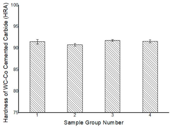
Figure 3.
Hardness of WC–Co cemented carbide.
3.3. Bending Strength Test of WC–Co Cemented Carbide
Using the bending strength tester, the bending strength of the sample was measured by a three-point test method. When carrying out the test, the midpoint of the samples must be set right in the middle of the two fulcrums. In order to ensure the accuracy of the test, the loading rod was at a speed of 600 N/s. The bending strength was calculated using the following formula:
where F (N) is the load of the cemented carbide specimen when it breaks; L (mm) is the span used in the experiment, the value of which was 10 mm; B (mm) is the width of the specimen, whose direction is perpendicular to the press head and the value of which was 3 mm; H (mm) was the height of the specimen, whose direction is parallel to the press head and the value of which was 2 mm.
According to Figure 4, the bending strength of the samples with 0.06 wt % graphene + 0.06 wt % carbon nanotubes increased by 49%, the bending strength of the samples with 0.12 wt % CNTs increased by 46%, and the bending strength of the samples with 0.12 wt % graphene increased by 68%. After graphene was dispersed in the cemented carbide bonding phase, its flexural strength was substantially improved. Because of its small volume and high strength, graphene played a certain role in the two-phase dispersion and reinforcement of the weak Co phase.
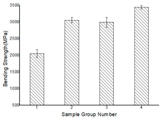
Figure 4.
Bending strength of WC–Co cemented carbide.
The cracks in cemented carbides usually propagated in the weakly adhesive Co phase, which ultimately led to fracture failure. When cracks propagated in the Co phase with insufficient yield strength, they encountered high-intensity graphene particles or carbon nanotubes, which forced them to deflect. As a result, the crack path became longer. Therefore, crack propagation and fracture were more difficult in the cemented carbide materials because the graphene and carbon nanotubes absorbed the external energy.
3.4. Fracture Toughness Test of WC–Co Cemented Carbide
The Vickers hardness of WC–Co cemented carbide was measured with the HV-120 Vickers hardness tester, and the fracture toughness was calculated by the indentation crack method. For conversion of the sum of crack lengths values into Palmqvist fracture toughness values, the formula was used:
where l is the crack length [32].
Hu [33] also obtained the Vickers hardness of cemented carbide through experiments and calculated the fracture toughness of the sample. The fracture toughness of WC-6Co in his experiment was 10.6 MPam1/2. As shown in Figure 5, the fracture toughness of the samples with graphene or carbon nanotubes has been improved.
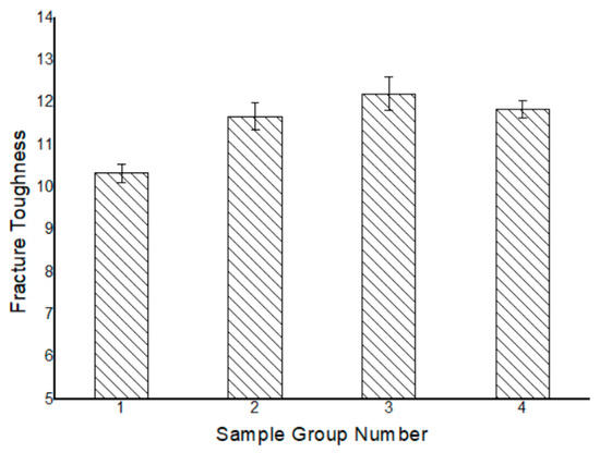
Figure 5.
Fracture toughness of WC–Co cemented carbide.
3.5. Metallographic Structure of WC–Co Cemented Carbide
After the coarse grinding of the samples with a diamond grinder, the samples were corroded, and the metallographic structure under the optical microscope was obtained.
According to metallographic structure, it could be seen in Figure 6 that the porosity, morphology, and distribution of the bonded phase of the sintered samples were basically the same under the same experimental conditions.
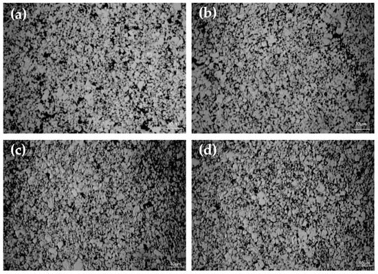
Figure 6.
(a) Metallographic of Group 1; (b) metallographic of Group 2; (c) metallographic of Group 3; (d) metallographic of Group 4.
In order to show the consistency of microstructures more practically and comprehensively, X-ray diffraction was used to explore the microstructures. The results can be seen as Figure 7. The microstructures of the four samples were in good agreement with the diffraction peaks of WC. This meant that, despite the addition of graphene and carbon nanotubes, the microstructure of cemented carbide matrix remained stable without any visible changes. The consistency of the microstructures was further confirmed.
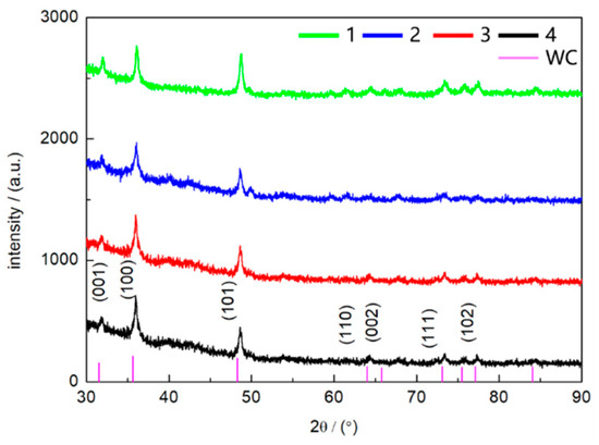
Figure 7.
The XRD patterns of four groups of cemented carbides.
3.6. SEM Analysis of WC–Co Cemented Carbide
The secondary electron and backscattered electron images of WC–Co cemented carbide with 0.12 wt % graphene were obtained in this experiment. The location of Co was found by comparing the difference between the secondary electron image and backscattered electron image. Energy dispersive X-ray spectroscopy of the Co phase at the sample plane was carried out (Figure 7).
3.6.1. Backscattered and Secondary Electron Images of WC–Co Cemented Carbide Samples
In order to investigate the distribution of graphene and carbon nanotubes, the Co phase needs to be found first. Because of the small mass fraction of Co, it was difficult to distinguish on the fracture surface. The method of comparing backscattered and secondary electron images was used (Figure 8). The yield of backscattered electrons is positively correlated with the atomic number. In the same field of view, the brighter parts of the secondary electron images looked darker in the backscatter electron images. Therefore, it meant that those parts had low mass contrast, and were determined to be Co. The composition distribution of the Co phase could then be analyzed to further explore the distribution of graphene and carbon nanotubes.
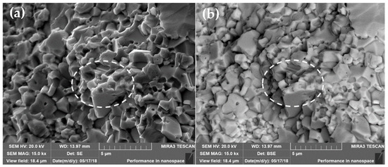
Figure 8.
(a) Secondary electron image; (b) backscattered electron image.
3.6.2. EDS Analysis of WC–Co Cemented Carbide Samples
Graphene and carbon nanotubes were basically distributed in the Co phase, so EDS was used to analyze the composition distribution of the Co phase to obtain the distribution of graphene and carbon nanotubes.
The composition distribution of area 1 is shown in Figure 9. By analyzing the composition distribution of Co, W, and C in area 1, it could be seen that the elemental distribution of Co and C coincided well with each other. In order to exclude the influence of C that came from WC, the composition distribution of WC and C in area 2 was determined. It could be seen that C was less distributed in the areas where W was aggregated. Therefore, it was difficult for C that came from WC to form the distribution in Figure 9d. This meant that a large amount of C was distributed in the Co phase. It is difficult for C and Co to form compounds, which meant that the graphene and carbon nanotubes were abundantly distributed in the cobalt phase. This further explains why graphene and carbon nanotubes enhanced the bending strength of the cemented carbide.
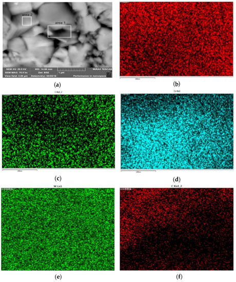
Figure 9.
(a) Image of areas used for EDS analysis; (b) distribution of W content in area 1; (c) distribution of Co content in area 1; (d) distribution of C content in area 1; (e) distribution of W content in area 2; (f) distribution of C content in area 2.
3.7. Finite Element Simulation of Heat Transfer Process of Gear Cutter of Shield Machine
The time integration for transient solid heat transfer in ABAQUS was based on the backward difference method.
Figure 10a is a model of a tooth cutter element for a shield machine with a side length of 30 mm. It was divided into two parts. Figure 10c is a shell with a thickness of 0.5 mm. The remaining part was treated as a whole body, as shown in Figure 10b. Next, the temperature of the shell part was set to 1500 °C, and the body part was set to 500 °C. It was assumed that the surface of the gear cutter was adiabatic and did not exchange heat with the outside world. The mesh of the gear cutter was divided using the DC3D4 element type, and the cell number was 1.3 × 10⁵, as shown in Figure 11. The density, the specific heat capacity, and the thermal conductivity of the original sample and the sample with 0.12% graphene were input into the calculation, and the dynamic heat transfer process of the teeth could be obtained.
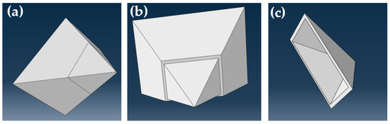
Figure 10.
(a) Model of tooth cutter element for shield machine; (b) body part; (c) shell part.
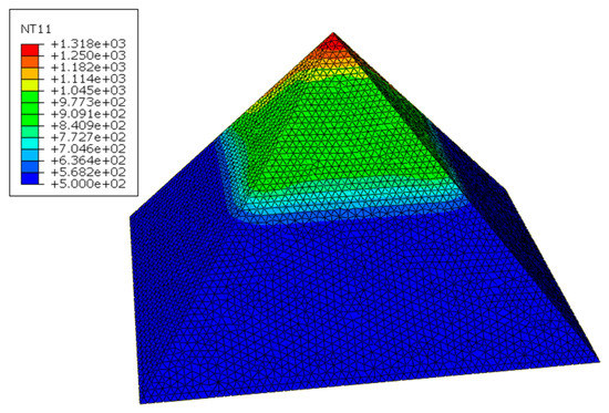
Figure 11.
Temperature nephogram of samples with graphene after 1 s heat transfer.
Figure 12a shows that the temperature of the graphene sample is always higher than that of the original sample during heat transfer and cooling. Figure 12b shows that the temperature difference increases rapidly at the beginning and then decreases rapidly after reaching its maximum value.
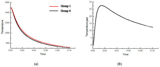
Figure 12.
(a) Temperature variation of the A-point original sample and the graphene-added sample with time; (b) temperature difference between the A-point sample and the graphene sample with time.
4. Conclusions
The Rockwell hardness of WC–Co cemented carbide with graphene and carbon nanotubes was above 88 HRA, which exceeded the performance requirements of existing shield machine tools with the same composition. With the addition of graphene and carbon nanotubes, the bending strength of cemented carbide increased by approximately 50%. After adding graphene and carbon nanotubes, the thermal conductivity of WC–Co cemented carbide increased. When the graphene content reached 0.12 wt%, the thermal conductivity increased by 9.86%. Reducing the working temperature prevented the Co phase from melting in extreme cases.
Author Contributions
Data curtion, Z.L.; Formal analysis, Z.L.; Investigation, K.C.; Methodology, J.W.; Project administration, W.X.; Resources, K.C., K.H. and X.R.; Writing—review & editing, W.X.
Funding
This research was funded by The Opening Subject of State Key Laboratory of Shield Machine and Boring Technology grant number 2014-02, National Natural Science Foundation of China grant number 51478146 and National Natural Science Foundation of China grant number 51327802.
Conflicts of Interest
The authors declare no conflict of interest.
References
- Yu, B.; Li, Y.; Lei, Q.; Nie, Y. Microstructures and mechanical properties of WC–Co-xCr-Mo cement carbides. J. Alloy. Compd. 2019, 771, 636–642. [Google Scholar] [CrossRef]
- Liu, X.H.; Zou, A.Z. Analysis and application of shield cemented carbide. Superhard Mater. Eng. 2016, 28, 24–26. [Google Scholar] [CrossRef]
- Chu, K.; Wang, X.H.; Wang, F.; Li, Y.B.; Huang, D.J.; Liu, H.; Ma, W.L.; Liu, F.X.; Zhang, H. Largely enhanced thermal conductivity of graphene /copper composites with highly aligned graphene network. Carbon 2018, 127, 102–112. [Google Scholar] [CrossRef]
- Zhang, Z.; Zhang, L.; He, J.; Wu, X. The Status and Prospect of Shield Cutters Industry. Cem. Carbide 2015, 32, 340–346. [Google Scholar]
- Heinrichs, J.; Olsson, M.; Yvell, K.; Jacobson, S. On the deformation mechanisms of cemented carbide in rock drilling. Fundamental studies involving sliding contact against a rock crystal tip. Int. J. Refract. Met. Hard Mater. 2018, 77, 141–151. [Google Scholar] [CrossRef]
- Mikado, H.; Ishihara, S.; Oguma, N.; Kawamura, S. On the short surface fatigue crack growth behavior in a fine-grained WC–Co cemented carbide. Metals 2017, 7, 254. [Google Scholar] [CrossRef]
- Wu, X.; Li, L.; He, N.; Zhao, G.; Shen, J. Experimental Investigation on Direct Micro Milling of Cemented Carbide. Micromachines 2019, 10, 147. [Google Scholar] [CrossRef] [PubMed]
- Gallardo, J.M.; Agote, I.; Astacio, R.; Schubert, T.; Cintas, J.; Montes, J.M.; Torres, Y.; Cuevas, F.G. Hard Metal Production by ERS: Processing Parameter Roles in Final Properties. Metals 2019, 9, 172. [Google Scholar] [CrossRef]
- Sribalaji, M.; Islam, A.; Mukherjee, B.; Pandey, M.K.; Keshri, A.K. Tailoring the thermal shock resistance of titanium carbide by reinforcement with tungsten carbide and carbon nanotubes. Ceram. Int. 2018, 44, 2552–2562. [Google Scholar] [CrossRef]
- Beste, U.; Coronel, E.; Jacobson, S. Wear induced material modifications of cemented carbide rock drill buRons. Int. J. Refract. Met. Hard Mater. 2006, 24, 168–176. [Google Scholar] [CrossRef]
- Yan, M. Study on Creep-Thermal Fatigue Life Prediction; Northeastern University: Boston, MA, USA, 2008. [Google Scholar]
- Pop, E.; Mann, D.; Wang, Q.; Goodson, K.; Dai, H. Thermal conductance of an individual single-wall carbon nanotube above room temperature. Nano Lett. 2005, 6, 96–100. [Google Scholar] [CrossRef]
- Balandin, A.A.; Ghosh, S.; Bao, W.; Calizo, I.; Teweldebrhan, D.; Miao, F.; Lau, C.N. Superior thermal conductivity of single-layer grapheme. Nano Lett. 2008, 8, 902–907. [Google Scholar] [CrossRef] [PubMed]
- Zhang, F. SPS Synthesis and Toughening Mechanism of Nano-WC/Co-Based Carbon Nanotube Composites; Harbin Institute of Technology: Harbin, China, 2005. [Google Scholar]
- Huang, Z.Q.; Li, W.; Li, Q.; Guo Eh Qiu, C.S. Experimental Research on the Composite Material of Nano-Al2O3/Cemented Carbide. Rare Met. Cem. Carbides 2011, 39, 16. [Google Scholar]
- Özbek, N.A.; Çiçek, A.; Gülesin, M.; Özbek, O. Investigation of the effects of cryogenic treatment applied at different holding times to cemented carbide inserts on tool wear. Int. J. Mach. Tools Manuf. 2014, 86, 34–43. [Google Scholar] [CrossRef]
- Yan, S.; Chen, X.; Hong, Q. Research Progress of Graphene Reinforced Aluminum Matrix Nanocomposites. J. Aeronaut. Mater. 2016, 36, 57–70. [Google Scholar]
- Zhao, T.; Ji, X.; Jin, W.; Yang, W.; Hu, J.; Dang, A.; Li, H.; Li, T. The preparation and electrochemical performance of graphene/carbon nanotube composite. Carbon Tech 2017, 36, 21–26. [Google Scholar]
- Boccarusso, L.; Scherillo, F.; Prisco, U. Effects of Cr3C2 addition on wear behaviour of WC-Co based cemented carbides. Metals 2018, 8, 895. [Google Scholar] [CrossRef]
- Aleksandrov Fabijanić, T.; Jakovljević, S.; Franz, M.; Jeren, I. Influence of Grain Growth Inhibitors and Powder Size on the Properties of Ultrafine and Nanostructured Cemented Carbides Sintered in Hydrogen. Metals 2016, 6, 198. [Google Scholar] [CrossRef]
- Konyashin, I.; Zaitsev, A.; Meledin, A.; Mayer, J.; Loginov, P.; Levashov, E.; Ries, B. Interfaces between Model Co-W-C Alloys with Various Carbon Contents and Tungsten Carbide. Materials 2018, 11, 404. [Google Scholar] [CrossRef]
- Armstrong, R.W. The hardness and strength properties of WC-Co composites. Materials 2011, 4, 1287–1308. [Google Scholar] [CrossRef]
- Ocak, B.C.; Yavas, B.; Akin, I.; Sahin, F.; Goller, G. Spark plasma sintered Zr C-Ti C-GNP composites: Solid solution formation and mechanical properties. Ceram. Int. 2018, 44, 2336–2344. [Google Scholar] [CrossRef]
- Ling, Z.C.; Yan, C.X.; Shi, Q.N.; Feng, Z.X.; Qu, Y.D.; Li, T.; Yang, Y.X. Effect of Ball Milling Time on Microstructure and Properties of Graphene/Copper Composites. Rare Met. Mater. Eng. 2017, 46, 207–212. [Google Scholar]
- Chen, Z.; Qian, J.; Ye, Y. Theoretical Calculation of Equivalent Thermal Conductivity of Composites. J. Univ. Sci. Technol. China 1992, 4, 416–424. [Google Scholar]
- Wang, H.; Webb, T.; Bitler, J.W. Study of thermal expansion and thermal conductivity of cemented WC–Co composite. Int. J. Refract. Met. Hard Mater. 2015, 49, 170–177. [Google Scholar] [CrossRef]
- Lin, F.; Bhatia, G.S.; Ford, J.D. Thermal conductivities of powder-filled epoxy resins. J. Appl. Polym. Sci. 2010, 49, 1901–1908. [Google Scholar] [CrossRef]
- Agari, Y.; Uno, T. Thermal conductivity of polymer filled with carbon materials: Effect of conductive particle chains on thermal conductivity. J. Appl. Polym. Sci. 2010, 30, 2225–2235. [Google Scholar] [CrossRef]
- Jin, P.; Peng, W. Research on Thermal Conductivity of Cemented Carbide. Cem. Carbide 2015, 32, 300–305. [Google Scholar]
- Zhou, G.; Ye, Z.; Shi, W. Application of three-dimensional, 3D, graphene and Its Composites. Prog. Chem. 2014, 26, 950–960. [Google Scholar]
- Xing, Y.; Yu, K.; Liu, Y.; Zhang, L. Research on the progress of high thermal conduction mechanism and heat transfer enhancenment application of graphene. Chem. Eng. 2015, 29, 54–60. [Google Scholar]
- Schubert, W.D.; Neumeister, H.; Kinger, G.; Lux, B. Hardness to Toughness Relationship of Fine Grained WC–Co. Int. J. Refract. Met. Hard Mater. 1998, 16, 133–142. [Google Scholar] [CrossRef]
- Hu, S. Understanding the Fracture Toughness Testing Method and Toughness Evaluation of WC–Co Based Cenmented Carbides; Hunan University: Changsha, China, 2013. [Google Scholar]
© 2019 by the authors. Licensee MDPI, Basel, Switzerland. This article is an open access article distributed under the terms and conditions of the Creative Commons Attribution (CC BY) license (http://creativecommons.org/licenses/by/4.0/).