Abstract
The multi-galvanic effect of an Al fin-tube heat exchanger was evaluated using polarization tests, numerical simulation, and the seawater acetic acid test (SWAAT). Determination of the polarization state using polarization curves was well correlated with numerical simulations using a high-conductivity electrolyte. However, the polarization results did not match those of the low-conductivity electrolyte due to the lower galvanic effect. Although the polarization state is changed by electrolyte conductivity, the total net current of the tube is decreased in the case of the anodic joint. From SWAAT results, the leakage time of Al fin-tube heat exchanger assembled by anodic joint was longer than the case with cathodic joint.
1. Introduction
Aluminum (Al) is a light metal that has interesting properties for heat exchanger applications (e.g., its low density, high thermal conductivity [1], good corrosion resistance [2], and good mechanical properties [3]) in the HVACR (heating, ventilation, air conditioning, and refrigeration) industry for use in cooling systems and air-ventilated units [4,5,6]. In the mid-1990s, the mechanical assembly of automotive heat exchangers started using brazed Al alloys, and this trend is currently applied in the heat exchangers of air conditioners [7]. In air conditioners, AA 1xxx and AA 3xxx series alloys are used because automotive heat exchangers do not require high mechanical properties and these series have higher thermal transfer efficiency and are economic advantages [8].
To increase the wettability of the melted filler metal at the surface, fluxing is used to remove the natural oxide layer covering the Al surface [9]. Due to the high temperature and cladding with the flux material [10,11], the geometry and microstructure of the joint region, tube, and fin are modified [12,13,14,15]. The microstructural change can influence the corrosion behavior. Thus, the microstructural effects on the corrosion properties after brazing should also be considered. In addition, the Al series used in the tube, fin, and joint (filler metal) are different according to their applications. In this study, AA 1100, AA 3003, and AA 4343 or modified AA 4343 are used in the tube, fin, and filler metal, respectively. For assembly of the fin and tube, each part underwent brazing and the fin-tube was jointed as shown in Figure 1. Although Al is used in all parts of the fin-tube heat exchanger, the different alloying elements in the Al series influence the corrosion properties, resulting in galvanic corrosion [16,17].
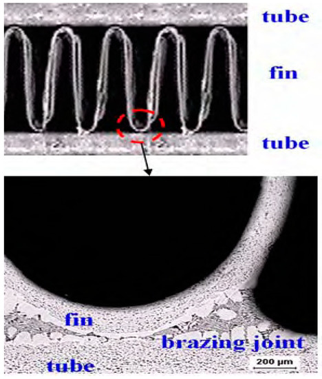
Figure 1.
Cross-sectional view of the Al fin-tube heat exchanger assembled by the brazing process.
An important consideration related to the corrosion protection of Al fin-tube heat exchangers is the galvanic coupling between the fin and tube materials. Generally, the material used in the fin has a more negative potential than the tube materials in order to provide cathodic protection for the tube. However, in the case of the Al fin-tube heat exchangers that are assembled by the brazing process, the brazing joint influences the galvanic coupling; this is called multi-material galvanic corrosion. The basic principles of galvanic corrosion are well established and commonly accepted, but galvanic corrosion in realistic situations, such as with multi-material coupling and complex geometries, is hard to predict. Fortunately, the advance of computational simulations has made it possible to model many complex corrosion situations; thus, computational simulation can be directly used to solve engineering design problems [18]. Computational simulation approaches are one of the most effective methods for corrosion design of a product.
Generally, the outside part of the Al fin-tube heat exchanger is the main corroded region because the acid rain and outside pollutants such as sulphur oxides (SOx) and nitrogen oxides (NOx) cause a severe corrosion problem. Thus, a test for outside corrosion is mainly considered for Al fin-tube heat exchanger. One of the corrosion reliability tests of the Al fin-tube heat exchanger is the sea water acetic acid test (SWAAT), which is a cyclic spray test (as opposed to a full immersion test). Therefore, in SWAAT, wet and high humidity environments are produced in turn. This indicates that the corrosion condition of the Al fin-tube heat exchanger is alternatively exposed to the thin-layer electrolyte and full immersion. The conductivities of full immersion electrolytes and thin-layer electrolytes are significantly different, which affects the potential and current distribution of the galvanic coupled metals [19]. Thus, the solution conductivity needs to be taken into account when designing a system that protects against galvanic corrosion. In this study, we evaluate the corrosion of Al fin-tube heat exchangers with different brazing joints in high- and low-conductivity electrolyte conditions based on computational simulations. Also, to compare the result of computational results, the actual SWAAT was conducted for Al fin-tube heat exchanger applied different joint materials. Although it would be not a perfect validation of simulation results, it can be supporting the simulation results for application of actual corrosion reliability test.
2. Boundary Element Method (BEM)
A model of an Al fin-tube heat exchanger is shown in Figure 2; this has electrolyte domains (Ωbulk and Ωthin-layer) and is surrounded by the surface of the electrolyte (Γn), the surface of the tube part (Γa), the surface of the fin part (Γb), and the surface of the joint part (Γc). The electrolyte conductivity (σ) is uniform in the whole domain and there is no current loss. The potential field in the electrolyte domain (Ω) can be modeled by Laplace’s equation [20]:
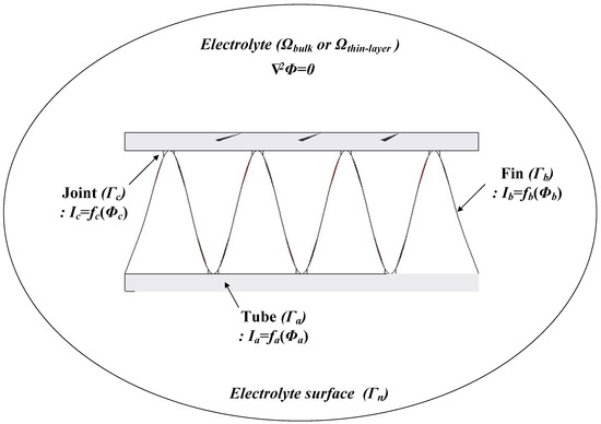
Figure 2.
Boundary conditions for corrosion simulation of the Al fin-tube heat exchanger.
Here, Φ is the electrical potential, which is the potential relative to a reference electrode, such as a saturated calomel electrode (SCE).
Laplace’s equation is calculated using the following boundary conditions:
i = i0, on Γn
ia = fa(Φa), on Γa
ib = fb(Φb), on Γb
ic = fc(Φc), on Γc
Here, Γ is the entire surface of the electrolyte domain, which includes Γn (electrolyte surface), Γa (tube surface), Γb (fin surface), and Γc (joint surface). fa(Φa), fb(Φb), and fc(Φc) are the non-linear functions on the surfaces of the tube, fin, and joint areas, respectively, which represent the experimentally achieved polarization curves. Thus, the boundary element method (BEM) can be used to calculate Laplace’s Equation (1) when the tube, fin, and joint areas are prescribed on the Al surface and their polarization curves are known [21]. Based on this, Φ and i on the whole surface can be determined.
An Al fin-tube heat exchanger model was created using the Rhinoceros 4.0 (Robert McNeel & Associates, Seattle, USA)3D drawing software based on the real shapes and dimensions. The inner parts of the heat exchanger were not modeled to avoid computational errors because outside corrosion is the main consideration in this study. The 3D model of the Al fin-tube heat exchanger, with detailed dimensions, is shown in Figure 3. The joint part is modeled by rectangular shape between the tube and fin to simplify the heat exchanger model. Areas of the tube, fin, and joint are 870, 1115, and 40 mm2, respectively. After modeling, the heat exchanger, the 3D model was imported into the program BEASY version 10.0r14, which is BEM-based software(BEASY, Southampton, England). Setting the boundary conditions is an essential step for corrosion simulation. Different electrolyte) conductivity values were applied for comparison of the bulk (0.4 S/m) and thin-layer (0.00004 S/m) electrolytes; this was done because the electrolyte conductivity is generally decreased in thin-layer electrolyte conditions. Although the oxygen concentration and ion transfer parameter can also influence the corrosion rate, we consider the electrolyte conductivity difference because the galvanic effect between the tube, fin, and joint is the main focus in this study. Also, the localized corrosion caused by galvanic corrosion is the important factor for corrosion reliability. However, the corrosion design for a large structure by simulation is the main goal of this study. Thus, not the localized corrosion which is focused on the micro-scale but the uniform corrosion in bulk structure was focused in this study.
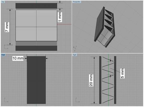
Figure 3.
3D models of the Al fin-tube heat exchanger with detailed dimensions (view of top, front, right and perspective).
3. Experimental Procedures
3.1. Materials and Solution
As mentioned above, AA 1100, AA 3003, and AA 4343 or modified AA 4343 (which was modified to include more Zn to decrease the corrosion potential), are used in the tube, fin, and filler metals, respectively. The chemical composition of each part is listed in Table 1. Cathodic and anodic joints indicate that the higher and lower corrosion potential than the tube materials. Fin material always has lower potential than tubes and joints for the corrosion protection of the tube. The test solution consisted of a seawater acidified solution which is a synthetic sea salt solution made with the addition of glacial acetic acid (pH 3.0), as described by ASTM G85. Test temperature of all the tests is 49 °C.

Table 1.
Chemical composition of the parts (Al 1100, Al 3003, Al 4343 and modified Al 4343) of Al fin-tube heat exchanger.
3.2. Potentiodynamic Tests
Polarization data for the different parts of the Al fin-tube heat exchanger (i.e., AA 1100, AA 3003, and AA 4343 or modified AA 4343) were needed to conduct simulations. Potentiodynamic polarization tests were conducted by a conventional three-electrode cell. A purified carbon rod was used as the counter electrode and a saturated calomel electrode (SCE) was used as the reference electrode. The tested specimen for carrying out the polarization test of each part was extracted from the Al fin-tube heat exchanger which was machined by a micro-cutting machine (The CUTLAM®micro 1.1, LAMPLAN, Gaillard, France). The working electrode was abraded by a series of abrasive papers (from 220 to 600 grit), rinsed ultrasonically with ethanol, and dried with nitrogen (N2) gas. The specimen was covered with silicone rubber, leaving an area of 25 mm2 unmasked. The prepared specimen was then exposed to the test solution for 1 h. Potentiodynamic polarization tests were carried out using a Bio-Logic VSP-300 potentiostat. The potential range was from −0.3 VSCE vs. the open-circuit potential (OCP) to −0.4 VSCE at a scan rate of 0.166 mV/s. All polarization tests were repeated a minimum of three times to ensure accuracy.
3.3. Sea Water Acetic Acid Test (SWAAT)
As a corrosion reliability test of fin-tube heat exchanger, SWAAT has been used in the field of Al fin-tube heat exchanger. Thus, to compare the corrosion reliability of Al fin-tube heat exchanger applied anodic and cathodic joint and validate the corrosion resistance of suggested joint materials, SWAAT was conducted in this study. SWAAT was produced based on ASTM G85 which utilizes the following cycle: 30-minute spray followed by a 90-minute soak at above 98% relative humidity and 49 °C. Whole Al fin-tube heat exchangers were tested to evaluate the tube leakage time caused by corrosion degradation. To record the leakage time caused by corrosion degradation, the tube was filled with air at the inlet part and the pressure gage was installed at the outlet part. Until the pressure gage was set to 5 MPa, the air was filled. The leakage of the Al fin-tube exchanger was determined from the decrease of a pressure gage during the SWAAT.
4. Results and Discussion
4.1. Polarization Curves
Figure 4 shows the polarization curves of the tube (AA 1100), fin (AA 3003), cathodic joint (AA 4343), and anodic joint (modified AA 4343) in the seawater acetic acid solution. Parameters such as the anodic and cathodic Tafel slopes (βa and βc), corrosion current density (icorr), and corrosion potential (Ecorr) were determined from the polarization curves and are listed in Table 2. Although icorr is different for each part of the Al fin-tube heat exchanger due to the alloying and microstructure effects [16,17,22,23,24], the actual current density in the Al-fin tube heat exchanger should vary due to the galvanic corrosion between the three metals. Ecorr exhibits the following decreasing order: cathodic joint > tube > anodic joint > fin. This means that the fin acts as a sacrificial anode for both of the assembled cases; cathodic joint > tube > fin and tube > anodic joint > fin. Thus, the effect of different tri-metal galvanic couplings on the corrosion reliability should be considered for designing Al fin-tube heat exchangers.
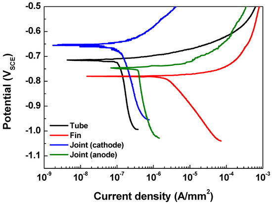
Figure 4.
Polarization curves of each part of the Al fin-tube heat exchanger.
Table 2.
Potentiodynamic polarization test results of different parts of the Al fin-tube heat exchanger (Al 1100, Al 3003, Al 4343, and modified Al 4343).
Generally, in tri-metal galvanic couples that include three metals (A1, A2, and A3) with different corrosion potentials in the order of EA1 > EA2 > EA3, the polarization of the middle potential metal (EA2) can be defined by the mixed potential theory [25,26]. If the tri-metal galvanic coupled metals (A1, A2, and A3) comply with the Tafel system (a linear system), the polarization state of the middle potential metal can be determined by the Tafel superposition relation. Thus, the tri-metal galvanic couple can be investigated by considering the A1-A2 and A2-A3 couples. Then, the net current (Inet) on the A2 metal can be determined as IA1-A2 IA2-A3, where IA1-A2 and IA2-A3 are currents flowing from A1 to A2 and from A2 to A3, respectively. This means that A2 acts as an anode in the case of a positive Inet and as a cathode in the case of a negative Inet.
Based on the above determination made via the polarization state method, the polarization states of the tube in the two assembled cases (case 1: fin-tube-cathodic joint and case 2: fin-tube-anodic joint) were determined. Schematic polarization curves of the tube, fin, and joint are shown in Figure 5, which reflect the area of the 3D model used to interpret the polarization state; this is done because the ratio of the cathode-to-anode surface areas is an important factor in galvanic corrosion. In case 1, the intersection between the Tafel slopes of the cathodic joint and the tube cannot occur. Thus, the galvanic currents on the anode parts, which are the anodic currents on the tube and fin (IT-CJ and IF-T), are not increased after galvanic coupling according to the mixed-potential theory. Alternatively, the galvanic currents on the cathodic parts, which are the cathodic currents on the cathodic joint and tube (ICJ-T and IT-F), are increased. Consequently, Inet of the tube in case 1 is negative, acting as a cathode. In case 2, the Tafel slopes of the anodic joint and tube make an intersection. The galvanic currents on the anode parts, which are the anodic currents on the anodic joint and fin (IAJ-T and IF-T), are increased only in the anodic joint and tube couple. The galvanic currents on the cathode parts, which are the cathodic currents on the tube (IT-AJ and IT-F), are increased in case 2. The value of Inet for the tube in case 2 is also negative, acting as a cathode. In short, the polarization state of the tube in both cases was cathodic; however, this determination did not consider the distance between the anode and cathode or the electrolyte conductivity. Thus, a more detailed determination is needed to design Al fin-tube heat exchangers adequately.
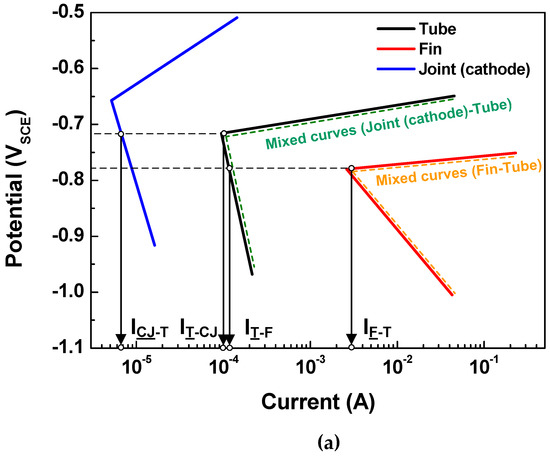
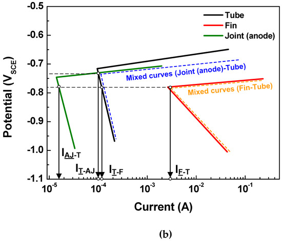
Figure 5.
Tafel slopes of the polarization curves applied to the surface areas of the tube, fin, and joint in the 3D model and the calculated galvanic current based on mixed-potential theory: (a) case 1 and (b) case 2.
4.2. Corrosion Simulation
Figure 6 and Figure 7 show the 3D models of the Al-fin tube heat exchanger with the cathodic and anodic joints, respectively, in high-conductivity electrolyte (0.4 S/m). The potential and current density ranges of the Al-fin tube heat exchanger assembled with a cathodic joint (Figure 6) were –775.2 mVSCE to −774.9 mVSCE and −2.21 10−7 A/mm2 to 3.52 10−7 A/mm2, respectively. While those of the Al-fin tube heat exchanger assembled with an anodic joint (Fig. 7) were −786.2 mVSCE to –786.1 mVSCE and −4.09 10−7 A/mm2 to 1.37 10-7 A/mm2, respectively. In both cases, the anodic current was observed only on the fin part and the current density increased near the tube and joint parts. This is due to the increased galvanic effect between the metals which had different corrosion potentials. The potential distribution was not broad (almost single potentials of −775 mVSCE and −786 mVSCE) in the anodic potential range of the fin. This means that the fin part acted as a sacrificial anode to the tube and joint (anodic and cathodic joints) in the high-conductivity electrolyte, regardless of the polarization state of the joint. This result is similar to the determination of the polarization state using the polarization curves.
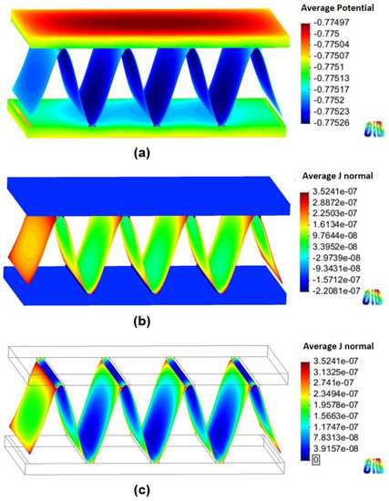
Figure 6.
Simulation results of the Al fin-tube heat exchanger assembled with a cathodic joint in high-conductivity electrolyte: (a) potential, (b) current density, and (c) anodic current density distribution.
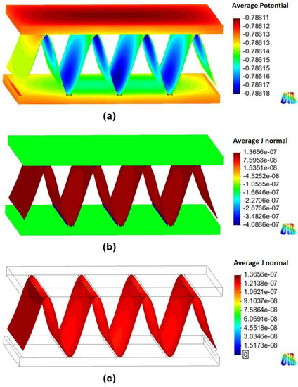
Figure 7.
Simulation results of the Al fin-tube heat exchanger assembled with an anodic joint in high-conductivity electrolyte: (a) potential, (b) current density, and (c) anodic current density distribution.
The total net currents of each part of cathodic or anodic joints in high-conductivity electrolyte were −8.87 10−6 A (cathodic joint), −5.93 10−5 A (tube), 6.81 10−5 A (fin) and −1.09 10−6 A (anodic joint), −5.94 10−5 A (tube), 6.05 10−5 A (fin). The total net current is related to the amount of current flowing from the anode or cathode. A decrease in the total net current simply indicates a decrease of the corrosion rate (according to Faraday’s law). Thus, the decrease of the total net current of the fin in the anodic joint implies increased corrosion life, which means that an anodic joint extends the corrosion life of the Al-fin tube heat exchanger compared to the cathodic joint in the high-conductivity electrolyte.
Figure 8 and Figure 9 show the 3D models of the Al-fin tube heat exchanger using cathodic and anodic joints in low-conductivity electrolyte (0.00004 S/m), respectively. Contrary to the results of the high-conductivity electrolyte, the potential distribution was clearly separated in each part of the Al fin-tube heat exchanger in both cases (anodic and cathodic joints). This means that the galvanic effect among the tube, fin, and joint was significantly decreased due to the low conductivity [19]. Also, these results indicate that the cathodic protection effect between exchanger components was very low, so that sufficient protection could not be obtained at the regions that are far away from the junction. The cathodic current was observed in the case of the cathodic joint, while anodic and cathodic currents were found in the case of the anodic joint. In the tube and fin, only the anodic current was shown, which implies that the current flow is too low to change the polarization state from anodic to cathodic. However, the anodic current was slightly decreased near the anodic joint (Figure 9c) because of a small current effect from the anodic joint. Consequently, the total net current was slightly lower in the case of the anodic joint (6.205 10−3 A) than in the case of the cathodic joint (6.329 10−3 A). However, according to the simulation results, the anodic joint was more favorable for extending the corrosion life of the Al fin-tube heat exchanger (especially in the tube part) in both conductivity environments. This can be verified by practical corrosion testing.
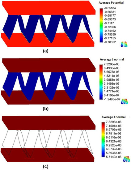
Figure 8.
Simulation results of the Al fin-tube heat exchanger assembled with a cathodic joint in low-conductivity electrolyte: (a) potential distribution, (b) current density distribution, and (c) current density distribution at the tube.
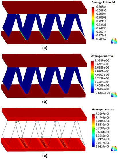
Figure 9.
Simulation results of the Al fin-tube heat exchanger assembled with an anodic joint in low-conductivity electrolyte: (a) potential distribution, (b) current density distribution, and (c) current density distribution at the tube.
4.3. SWAAT Test
To compare the corrosion lifetimes of Al fin-tube heat exchangers assembled with cathodic or anodic joints, SWAAT was conducted until leakage of the tube occurred. The polarization states of the Al fin-tube heat exchangers assembled by cathodic or anodic joints and the corresponding leakage time are listed in Table 3. Although the polarization state was changed according to the electrolyte conductivity, the anodic joint was efficient in extending the corrosion life because the anodic joint either decreased the net current on the fin or it protected the tube by serving as a sacrificial anode. In short, based on the corrosion simulation results, it was revealed that the anodic joint can increase the corrosion life. In SWAAT, an increase in the corrosion life was observed on the Al fin-tube assembled with an anodic joint. The leakage time in the case of the anodic joint was increased by about 42% relative to the lifetime with the cathodic joint. This suggests that the numerical simulation results correlated well with the corrosion test of the product. Thus, corrosion simulations can be helpful for the design of Al fin-tube assembly in low and high-conductivity electrolytes.
Table 3.
Sea water acetic acid test (SWAAT) results and polarization states of Al fin-tube heat exchangers assembled with cathodic or anodic joints.
5. Conclusions
In this study, the multi-galvanic effect in Al fin-tube heat exchangers assembled with cathodic or anodic joints was investigated using a polarization determination method and numerical simulation in the presence of electrolytes with high and low conductivities. SWAAT was also conducted to verify the simulation results. When determining the polarization state from the polarization curves, the tube and joint were found to be cathodes, while the fin acted as an anode, regardless of the corrosion potential of the joint. These results are in good agreement with the numerical simulation results in the high-conductivity environment. However, discrepancies were observed in the low-conductivity environment because the galvanic effect between the fin, tube, and joint was small. Although the polarization state changed according to the electrolyte conductivity, the total net current of the tube, which is related to the corrosion rate, was lower in the case of the anodic joint. Thus, the Al fin-tube heat exchanger assembled with the anodic joint was superior to the exchanger assembled with the cathodic joint. This result was verified by SWATT, and the leakage time of the Al fin-tube heat exchanger assembled with the anodic joint was 42% longer than that of the exchanger assembled with the cathodic joint. Due to the good correlation with the practical corrosion test results, numerical simulation of the multi-galvanic situation can be applied to improve the corrosion design of products.
Author Contributions
Conceptualization, Y.-S.K. and I.-J.P.; Methodology, X.X.; Software, Y.-S.K.; Validation, Y.-S.K. and I.-J.P.; Formal Analysis, Y.-S.K. and I.-J.P.; Investigation, Y.-S.K.; Resources, J.-G.K.; Data Curation, Y.-S.K.; Writing-Original Draft Preparation, Y.-S.K.; Writing-Review & Editing, X.X.; Visualization, J.-G.K.; Supervision, J.-G.K.; Project Administration, J.-G.K.; Funding Acquisition, J.-G.K.
Funding
This work was supported by the National Research Foundation of Korea (NRF) grant funded by the Korea Government (Ministry of Education, Science and Technology) (No.NRF-2016R1A2B4016027).
Conflicts of Interest
The authors declare no conflict of interest.
Nomenclature
| i | Current density, A/mm2 |
| V | potential, VSCE |
| icorr | corrosion current density, μA/mm2 |
| Ecorr | corrosion potential, VSCE |
| βa | anodic Tafel slope, V/decade |
| βc | cathodic Tafel slope, V/decade |
| Inet | net current, A |
Subscripts
| Ω | electrolyte domain |
| Ωbulk | bulk electrolyte domain |
| Ωthin-layer | thin-layer electrolyte domain |
| Γn | surface of the electrolyte |
| Γa | surface of the tube part |
| Γb | surface of the fin part |
| Γc | surface of the joint part |
| Φ | electrical potential |
| fa(Φa) | non-linear functions of the tube surface |
| fb(Φb) | non-linear functions of the tube fin |
| fc(Φc) | non-linear functions of the tube joint |
| A1, A2, and A3 | three metals |
| EA1, EA2, and EA3 | corrosion potential of three metals, V |
| IA-B | net current of A in galvanic condition between A and B |
Abbreviation
| Aluminum | Al |
| heating, ventilation, air conditioning, and refrigeration | HVACR |
| sulphur oxides | SOx |
| sea water acetic acid test | SWAAT |
| saturated calomel electrode | SCE |
| 3 dimension | 3D |
| American Society for Testing and Materials | ASTM |
| nitrogen | N2 |
| open-circuit potential | OCP |
References
- Andreatta, F.; Anzytti, A.; Fedrizzi, L. Corrosion behaviour of AA 8xxx aluminium fins in heat exchanger. Surf. Interface Anal. 2016, 48, 789–797. [Google Scholar] [CrossRef]
- Tierce, S.; Pébère, N.; Blanc, C.; Casenave, C.; Mankowski, G.; Robidou, H. Corrosion behaviour of brazing material AA 4343. Electrochim. Acta 2006, 52, 1092–1100. [Google Scholar] [CrossRef]
- Adams, T.M.; Dowling, M.F.; Abdel-Khalik, S.I.; Jeter, S.M. Applicability of traditional turbulent single-phase forced convection correlations to noncircular microchannels. Int. J. Heat Mass Trans. 1999, 42, 4411–4415. [Google Scholar] [CrossRef]
- Akers, W.W.; Rosson, H.F. Condensation inside a horizontal tube. Chem. Eng. Prog. S Ser. 1960, 56, 145–150. [Google Scholar]
- Cavallini, A.; Col, D.D.; Doretti, L.; Matkovic, M.; Rosetto, L.; Zilio, C. Condensation in horizontal smooth tubes: A new heat transfer model for heat exchanger design. Heat Transf. Eng. 2006, 27, 31–38. [Google Scholar] [CrossRef]
- Abdulstaar, M.; Mhaede, M.; Wagner, L.; Wollmann, M. Corrosion behaviour of Al 1050 severely deformed by rotary swaging. Mater. Design 2014, 57, 325–329. [Google Scholar] [CrossRef]
- Hong, M.S.; Park, I.J.; Kim, J.G. Alloying effect of copper concentration on the localized corrosion of aluminum alloy for heat exchanger tube. Met. Mater. Int. 2017, 23, 708–714. [Google Scholar] [CrossRef]
- Chen, G.; Chen, Q.; Wang, B.; Du, Z. Microstructure evolution and tensile mechanical properties of thixoformed high performance Al–Zn–Mg–Cu alloy. Met. Mater. Int. 2015, 21, 897–906. [Google Scholar] [CrossRef]
- ASM International, Materials Park. Metals Handbook: Welding and Brazing, 8th ed.; ASM International, Materials Park: Novelty, OH, USA, 1971; Volume 6. [Google Scholar]
- Tierce, S.; Pébère, N.; Blanc, C.; Mankowski, G.; Robidou, H.; Vaumousse, D.; Lacaze, J. Solidification and phase transformations in brazed aluminum alloys used in automotive heat exchangers. Int. J. Cast. Met. Res. 2005, 18, 370–376. [Google Scholar] [CrossRef]
- Lacaze, J.; Tierce, S.; Lafont, M.C.; Thebault, Y.; Pébère, N.; Mankowski, G.; Blanc, C.; Robidou, H.; Vanmosse, D.; Daloz, D. Study of the microstructure resulting from brazed aluminium materials used in heat exchangers. Mater. Sci. Eng. A 2005, 413, 317–321. [Google Scholar] [CrossRef]
- Sekulić, D.P. Molten aluminum equilibrium membrane formed during controlled atmosphere brazing. Int. J. Eng. Sci. 2001, 39, 229–241. [Google Scholar] [CrossRef]
- Sekulic, D.P.; Zellmer, B.J.; Nigro, N. Influence of joint topology on the formation of brazed joints. Model. Simul. Mater. Sci. Eng. 2001, 9, 357–370. [Google Scholar] [CrossRef]
- Zellmer, B.J.; Nigro, N.; Sekulic, D.P. Numerical modelling and experimental verification of the formation of 2D and 3D brazed joints. Model. Simul. Mater. Sci. Eng. 2001, 9, 339–355. [Google Scholar] [CrossRef]
- Marshall, G.J.; Bolingbroke, R.K.; Gray, A. Microstructural control in an aluminum core alloy for brazing sheet applications. Metall. Trans. A 1993, 24A, 1935–1942. [Google Scholar] [CrossRef]
- Al-Kharafi, F.M.; Badawy, W.A. Corrosion and passivation of Al and Al-Si alloys in nitric-acid solutions II-Effect of chloride ions. Electrochim. Acta 1995, 40, 1811–1817. [Google Scholar] [CrossRef]
- Abdel Rehim, S.S.; Hassan, H.H.; Amin, M.A. Chronoamperometric studies of pitting corrosion of Al and (Al-Si) alloys by halide ions in neutral sulphate solution. Corros. Sci. 2004, 46, 1921–1938. [Google Scholar] [CrossRef]
- Amaya, K.; Aoki, S. Effective boundary element methods in corrosion analysis. Eng. Anal. Bound. Elem. 2003, 27, 507–519. [Google Scholar] [CrossRef]
- McCafferty, E. Distribution of potential and current in circular corrosion cells having unequal polarization parameters. J. Electrochem. Soc. 1997, 124, 1869–1878. [Google Scholar] [CrossRef]
- Adey, R.A.; Niku, S.M. Computer modeling of galvanic corrosion. ASTM Spec. Tech. Publ. 1998, 978, 96–117. [Google Scholar]
- Ridha, M.; Amaya, K.; Aoki, S. Boundary element simulation for identification of steel corrosion in concrete using magnetic field measurement. Corrosion 2005, 61, 784–791. [Google Scholar] [CrossRef]
- Jafarian, F.; Umbrello, D.; Jabbaripour, B. Indentification of new material model for machining simulation of Inconel 718 ally and the effect of tool edge geometry on microstructure changes. Simul. Model. Pract. Theory 2016, 66, 273–284. [Google Scholar] [CrossRef]
- Gastli, A.; Metwally, I.A. Computation of eddy-current density on ESP motor and well casings under different operating conditions. Simul. Model. Pract. Theory 2008, 16, 483–493. [Google Scholar] [CrossRef]
- Nisançiöglu, K. Electrochemical behavior of aluminum-base intermetallics containing iron. J. Electrochem. Soc. 1990, 137, 69–77. [Google Scholar] [CrossRef]
- Jones, D.A. Principles and Prevention of Corrosion, 2nd ed.; Prentice Hall: Upper Saddle River, NJ, USA, 1996. [Google Scholar]
- Hu, Q.F.; Zhang, T.; Geng, S.J.; Wang, F.H. A method for determining the polarization state of the metal with the middle potential in order to calculate the corrosion rate of multi-metals complicated galvanic couple. Mater. Corros. 2017, 68, 935–942. [Google Scholar] [CrossRef]


© 2019 by the authors. Licensee MDPI, Basel, Switzerland. This article is an open access article distributed under the terms and conditions of the Creative Commons Attribution (CC BY) license (http://creativecommons.org/licenses/by/4.0/).