Article

Wear and Cavitation Erosion Resistance of an AlMgSc Alloy Produced by DMLS

Department of Mechanical and Industrial Engineering, University of Brescia, Via Branze, 38, 25123 Brescia, Italy
*
Author to whom correspondence should be addressed.
Metals 2019, 9(3), 308; https://doi.org/10.3390/met9030308
Submission received: 15 February 2019 / Revised: 2 March 2019 / Accepted: 4 March 2019 / Published: 8 March 2019
(This article belongs to the Special Issue Processing-Structure-Property Relationships in Metals)

Abstract

:
Pin-on-disk and cavitation tests were performed on an innovative Al-Mg alloy modified with Sc and Zr for additive manufacturing, which was tested in annealed condition. The damaging mechanisms were studied by observations of the morphology of the sample surface after progressive testing. These analyses allowed the identification of an adhesive wear mechanism in the first stages of pin-on-disk test, which evolved into a tribo-oxidative one due to the formation and fragmentation of an oxide layer with increasing testing distance. Regarding cavitation erosion, the AlMgSc alloy was characterized by an incubation period of approximately 1 h before mass loss was measured. Once material removal started, mass loss had a linear behavior as a function of exposure time. No preferential sites for erosion were identified, even though after some minutes of cavitation testing, the boundaries of melting pools can be seen. The comparison with literature data for AlSi10Mg alloy produced by additive manufacturing technology shows that AlMgSc alloy exhibits remarkable wear resistance, while the total mass loss after 8 h of cavitation testing is significantly higher than the value recorded for AlSi10Mg alloy in as-built condition.

1. Introduction

Metal additive manufacturing (AM) is an innovative but already established material processing technology for the production of parts and prototypes based on layer-by-layer build-up [1]. This technique allows an unrivalled design freedom, not reachable via conventional manufacturing routes, combined with a high quality and outstanding mechanical properties [1,2,3,4,5]. Nowadays, metal AM is regularly applied with different engineering materials like stainless steel [6,7,8], Ti, Co, and Ni alloys [9,10,11,12], and, lately, also Al alloys are used [1,13,14].
Regarding AM processing of Al alloys, attention has been mainly concentrated on the Al-Si system due to the good compromise between its mechanical properties, corrosion resistance, and processability [15]. Nevertheless, some studies focused also on an innovative Al-Mg alloy modified with Sc and Zr for additive manufacturing, commercially known as Scalmalloy®. This alloy showed outstanding strength and ductility, together with very low anisotropy [16]. In this regard, the alloy is characterized by an overall fine-grained structure, which limits the influence of building direction. The formation of this fine grain structure is due to various factors, as for instance the presence of Sc and Zr. These elements allow the formation of primary Al3(Sc, Zr) particles that act as nucleants for the Al matrix solidification [17,18], which is also favored by the similar crystal lattice constants of Al and Al3(Sc, Zr) phase. This, together with the high cooling rates typical for the process, leads to the formation of fine and equiaxed grains during the first stages of solidification. Some studies [17,19] also report the formation of slightly bigger columnar grains that nucleate on the fine-grained regions and grow radially towards the melt pool boundary. However, other authors [20] identify only a non-uniform distribution of Al3(Sc, Zr) particles inside the melting pools, with segregation of these particles along the bottom boundary (boundary between layers), while few particles are observed in the center, without referring to areas with different grain structure.
In general, after solidification, Al3(Sc, Zr) particles are located at grain boundaries and, therefore, hinder grain growth due to repeated heating of the material during the building process [21] and eventual post-treatment (annealing or hot isostatic pressing) [16]. This enhances a stable fine-grained structure of the material. Finally, annealing treatment in the range of 325–350 °C has been demonstrated to improve mechanical properties [16]. This is due to the further Al3(Sc, Zr) particle formation inside the Al-matrix: in this case, the precipitates have a smaller size than the primary particles and are coherent with the matrix [16], contributing to increasing material hardness. From a microstructural point of view, oxides and intermetallic phases containing Fe and Mn can be present, especially at grain boundaries. Among these, Mg-oxides, coming from the initial powder or forming during the solidification of melting pools, are often identified and are believed to behave as nucleants for the formation of primary Al3(Sc, Zr) from the liquid. Such microstructural features are clearly responsible for the mechanical properties of the alloy, which are also affected by other factors, such as laser scan speed [21], laser power [19], or platform temperature [22].
Besides tensile, hardness, or corrosion properties, wear resistance is an important parameter to evaluate possible new applications of Scalmalloy®. In general, wear resistance of AM Al-based alloys has not been widely investigated in the scientific literature and studies are mainly available for the sliding wear mechanism of Al-Si alloys [23]. In this case, the effect of heat treatment and size of Si particles was studied [24]. It was found that the material in as-built condition exhibits the lowest wear rate as compared to annealed AM samples and cast samples. This is due to the higher hardness of the as-built material caused by the fine network of Si particles uniformly distributed in the Al matrix. Similarly, also Kang et al. investigated the wear behavior of AlSi12 [25] and AlSi50 [26] alloys as a function of building parameters. It was confirmed that Si particle size plays a key role in wear resistance and that optimized values of laser power have to be applied in order to obtain nano-sized Si particles, beneficial for material hardness and wear resistance. Furthermore, density and, therefore, porosity levels were found to strongly affect material performance. In addition, AlSi10Mg-TiC [27], AlSi10Mg-TiB2 [28], AlSi10Mg-AlN [29], and Al-12Si-TNM composites [30] produced by additive manufacturing technologies exhibited remarkable wear resistance, once the processing parameters were optimized. Nevertheless, to date, only one study reported on the tribological behavior of AlMgSc alloy [20], produced by selective laser melting (SLM), as a function of scan speed. It was found that this parameter significantly affects the wear rate in dry condition since relatively low scan speed was responsible for good wear properties, while these decrease with increasing scan speed. Accordingly, also the wear mechanism changed, with a prevalent abrasion wear behavior at high scan speed. However, the effect of the annealing treatment was not considered, which is widely applied to AM components as well as suggested by material producers [31] and can affect the wear resistance of the material.
Furthermore, another important wear phenomenon scarcely investigated for AM alloys is cavitation erosion. This damaging mechanism is critical for several components in the hydraulic (valves, pumps, impellers, etc.) or automotive field (pistons, cylinders, combustion chambers, etc.) [32,33], which are all in contact with fluids. Lately, some studies [34,35] investigated the cavitation resistance of AlSi10Mg alloy fabricated by SLM, also in comparison with the corresponding casting or wrought alloy. Experimental tests revealed an extremely high cavitation erosion resistance of the AM alloy, especially in as-built condition due to the fine microstructure and high hardness. Given the already recognized performance of the AlMgSc alloy, it appears reasonable to investigate its cavitation erosion resistance in order to provide a wider characterization of its properties in order to evaluate new applications.
Therefore, in this study, sliding wear and cavitation erosion resistance of AlMgSc alloy were investigated. Samples were tested after annealing treatment in order to reproduce the actual use condition of the material. The aim is to identify the damaging mechanisms in order to evaluate possible applications where the AlMgSc alloy can experience this type of damage.

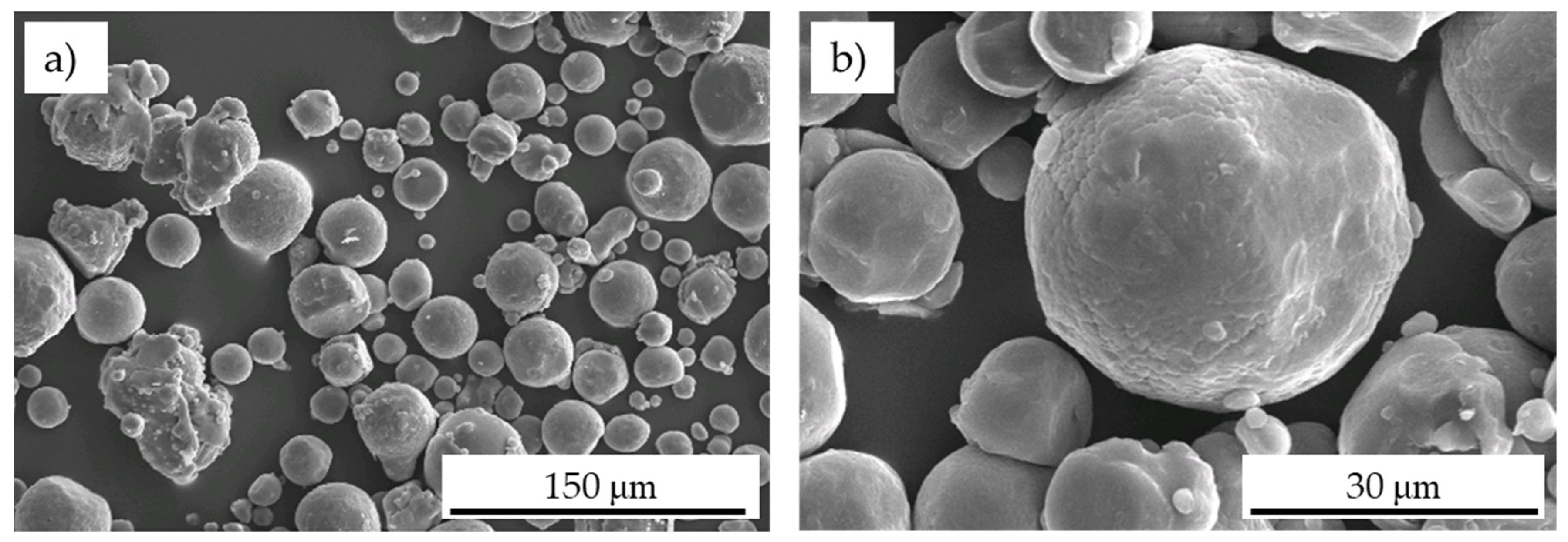
2. Materials and Methods

The mean chemical composition of the Scalmalloy® powder, used to produce samples for the present study, is reported in Table 1.
Morphological and dimensional characterization of the powder used for the AM process was carried out by scanning electron microscopy (SEM) (LEO EVO 40, Carl Zeiss AG, Milan, Italy).
Plates with a thickness of 2 mm along the y-axis and an area of 21 cm2 in the xz plane were produced by direct metal laser sintering (DMLS) (EOS M 290 machine with Yb-fiber laser, maximum power 400 W, 20 m3/h inert gas supply, F-theta lens, focus diameter of 100 μm, EOS GmbH Electro Optical System; EOS srl, Krailling, Germany), as shown in Figure 1. The following parameters were used: laser scan speed of 1300 mm/s, laser power of 370 W, hatch spacing of 90 μm, layer thickness of 30 μm. Before testing, samples were heat treated (annealing) at 325 °C for 4 h [16].
Microstructural characterization and microhardness measurements were performed on samples in as-built and annealed conditions, while sliding wear and cavitation erosion tests were carried out only on samples in annealed condition, since annealing is widely applied to AM components, as also suggested by the material producers [31].
Samples were analyzed by means of optical (Leica DMI 5000M, Wetzlar, Germany) and scanning electron microscopy (LEO EVO 40, Carl Zeiss AG, Milan, Italy), coupled with EDS (energy dispersive spectroscopy, Oxford Instruments, Wiesbaden, Germany) microprobe, after sample polishing up to mirror finishing. In order to observe melting pools, samples were etched with a 10% phosphoric acid (H3PO4) solution. Vickers microhardness measurements before and after annealing treatment were performed with a Mitutoyo HM-200 hardness testing machine (Mitutoyo Italiana srl, Lainate, Italy) with an applied load of 200 g and a loading time of 15 s. The results are presented as average values of at least 20 measurements per sample, to guarantee reliable statistics.
Pin-on-disk tests were performed in dry condition according to ASTM G99 standard [36] using a THT tribometer (CSM Instruments, Peseux, Switzerland). Samples for wear test (xz surface, see Figure 1) were polished up to mirror finishing in order to reach a roughness Ra lower than 0.8 µm, according to ASTM G-99 standard requirements. The counterpart was a 100Cr6 steel ball with a 6 mm diameter. A linear speed of 4 cm/s and a load of 1 N were applied for a total distance of 100 m. The diameter of wear tracks was 3 mm. During the tests, the friction force was monitored, and the friction coefficient was subsequently obtained. The test was repeated twice. The second test was periodically interrupted to observe the evolution of worn surface by SEM. Additionally, a stylus profilometer (Mitutoyo SJ301, Mitutoyo Italiana srl, Lainate, Italy) was used to record the track profile after each interruption. Five measurements were carried out in different positions for each track and the mean value and standard deviation were then calculated. The same track profile measurements were performed at the end of the test. Then, the worn volume was calculated multiplying the worn area and the track length. The wear rate was determined by the equation reported in [37]. Finally, this second test was prolonged up to 500 m in order to compare the obtained wear rate with data available in the scientific literature for AlSi10Mg alloy produced by AM technology.
Regarding cavitation tests, the x-z surface (Figure 1) was exposed to cavitation after mirror polishing, as done for sliding wear experiments. Cavitation tests were carried out according to ASTM G32 [38], following the stationary specimen approach. An ultrasonic device with a vibration frequency of 20.0 kHz, a vibration amplitude of 50 μm, and an electrical peak power of 2 kW was used in the present study. The ultrasonic probe was composed of a Ti6Al4V waveguide and a final amplification horn realized in Inconel 625 [35]. The specimen was inserted in a properly designed holding system and immersed in a tank containing water, at a distance of 0.50 mm from the horn surface. The test was periodically stopped in order to measure the weight loss and observe the morphology of the eroded surface by means of scanning electron microscopy. The total duration of the test was set at 8 h, according to previous works by the authors [35]. Results are presented in terms of cumulative mass loss and mass loss rate as a function of exposure time.

3. Results and Discussion

3.1. Microstructure and Hardness

The morphology of powders used for the DMLS process is shown in Figure 2. Most particles have an overall spherical shape, even though some have an irregular morphology and several satellites are present, likely due to the atomization process [39]. Measured powder size resulted in the range of 5–70 μm.
Micrographs of the x-y surface are shown in Figure 3 before and after annealing treatment. In both cases, the boundaries of scan tracks are visible as darker areas, confirming the very stable microstructure of this alloy even at high temperatures, as previously reported [16]. Here, according to previous studies on the same alloy, a higher density of primary Al3(Sc, Zr) particles [15] and extremely fine equiaxed grains were expected [17]. In the center of the melting pools, bigger columnar grains are usually found [17,19] and coherent Al3(Sc, Zr) precipitates form during annealing [16]. Some porosities, indicated by arrows in Figure 3, were present due to the building process [40]. In fact, it is well known that spherical porosities can be found in AM material as a consequence of entrapment of the inert gas present in the building environment during laser scanning and the subsequent fast solidification, because of melt splashing, Marangoni flow, or gas entrapment due to vaporization of low melting point constituents in the alloy [40,41,42]. In addition, non-spherical process-induced defects can be identified. These are usually shrinkage and lack of fusion porosities which occur due to the solidification conditions and a poor overlap of melting pools during the building process resulting in incomplete melting of the powder, respectively [43].
Samples were also observed along the building direction (Figure 4) and the typical structure of AM alloys, characterized by layers of melting pools, is visible. The microstructural interpretation of the areas with dark and light color is the same as described for Figure 3.
To confirm these assumptions, SEM analyses were performed at higher magnifications (Figure 5). The images show an agglomeration of particles (dark points) along the melting pool boundaries. As already demonstrated by many authors [17,18,20], these particles are Al3(Sc, Zr) particles (dark points), which are known to agglomerate along the melting pool boundaries [17,20].
The effectiveness of the annealing treatment on material hardness [16] is demonstrated by the microhardness values in Table 2. A significant increase was measured in agreement with other studies on the same alloy [16,22]. As mentioned in the introduction to this article, this is due to the precipitation of coherent Al3(Sc, Zr) particles that strengthen the material [16,22].

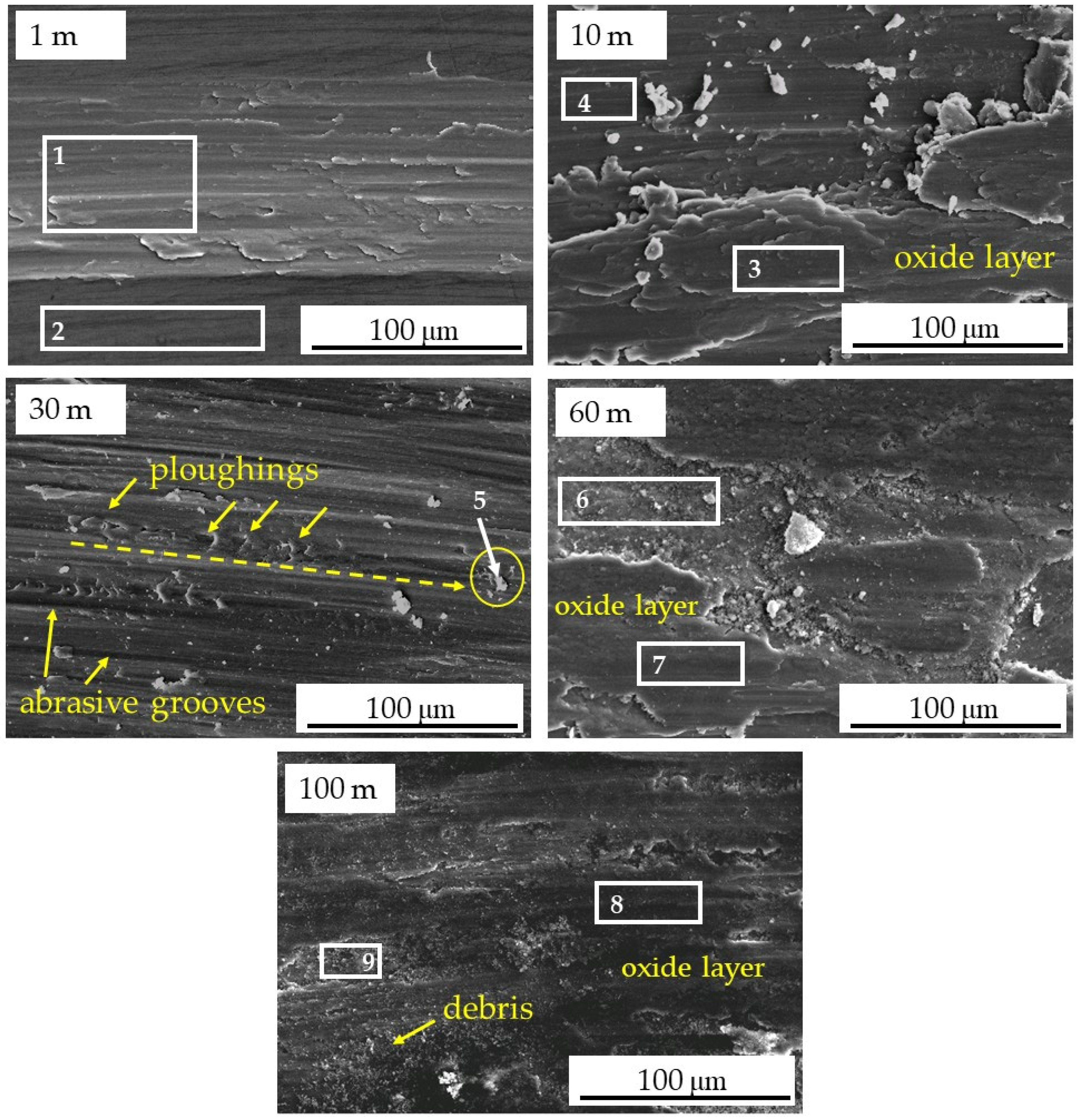
3.2. Wear Resistance

The evolution of the friction coefficient during the sliding test is plotted in Figure 6. The initial relative high friction coefficient may be due to the presence of asperities of the two surfaces in contact. These were progressively deformed and fragmented due to the high local compressive pressure and shear stress, as typically described for the sliding wear mechanism [44]. This lead to a progressive decrease in the friction coefficient at the early stages of sliding wear. In fact, it was observed that the friction coefficient decreased during the first meters until it reached a minimum value of approximately 0.45. After this transient, the friction coefficient slightly increased and reached a steady value of 0.52.
In order to gain further information on the wear mechanism, wear rate obtained by periodical interruptions of the test are shown in Figure 7. The wear rate decreased with increasing testing distance since material removal was faster in the first stages of testing and then it reached a steady condition since other phenomena besides material removal take place.
The obtained results appear very promising if compared with the wear resistance of an AlSi10Mg alloy produced by DMLS. In fact, for AlSi10Mg alloy, a wear rate of 1.80 × 10⁻³ mm3/N·m [28] after 500 m was reported, while a wear rate of 0.90 × 10⁻³ mm3/N·m was calculated for the AlMgSc alloy characterized in the present study after the same sliding distance.
These results in terms of the friction coefficient and wear rate suggest a change in the wear mechanism during the test that was better studied by SEM observations of the morphology of the worn area after progressive sliding distances, indicated by arrows in Figure 6.
From the images in Figure 8, the increase in track width with an increasing sliding distance of up to 30 m is evident. In addition, coarse oxide fragments are visible outside the worn track after 10 m testing, while they were absent for shorter sliding distances, providing evidence of significant material removal in this range (1–10 m) in agreement with the results in Figure 7.
Images at higher magnification (Figure 9) allow to better appreciate the morphology of the worn surfaces. After 1 m testing, the sample surface appeared quite smooth, and it was covered with an adhesion layer (Figure 9, 1 m) due to the plastic deformation of the material asperities [45]. Corresponding EDS analyses (Table 3) revealed the absence of an oxide layer, which was present instead when the sample was tested for a sliding distance of 10 m, even though this oxide was not uniformly present on the worn track (Figure 9, 10 m). The formation of a more and more uniform oxide layer contributed to a decrease in the friction coefficient recorded up to 30 m [46], together with the deformation and fragmentation of surface asperities, as mentioned above. Oxide formation on Al alloys during sliding test in air is a well-known phenomenon, which is caused by the local temperature rise due to frictional heating during sliding and applied load [47,48,49].
Regarding the next step (30 m), abrasive fragments and parallel grooves were visible in the worn track. In addition, ploughings due to the dragging of an oxide particle that was finally embedded in the Al alloy were identified (as indicated in Figure 9, 30 m). These were due to the delamination and breaking of the oxide layer, which created debris that remained in the wear track and caused the increase in the friction coefficient measured for the further duration of the test. Observations of the surface after 60 and 100 m (Figure 9, 60 m; Figure 9, 100 m) confirmed this interpretation and proved a change into a tribo-oxidative wear mechanism. The surface appeared covered by an oxide scale, and abundant small oxide particles, acting as third body, were present in the worn tracks, especially in areas where the oxide layer was removed.

3.3. Cavitation Resistance

Results from cavitation tests are presented in Figure 10 in terms of cumulative mass loss (Figure 10a) and mass loss rate (Figure 10b) as a function of exposure time for one test, representative of material behavior. The second repetition of the test confirmed the same trend of mass loss due to cavitation exposure. An incubation period of 55 ± 2 min was measured for the studied material. According to ASTM G32 [38], during this incubation period, the material experiences an accumulation of plastic deformation and internal stresses before significant material loss, and this corresponds to a period during which the erosion rate is zero.
After the incubation period, the erosion rate (Figure 10b) increased abruptly and then maintained quite constant values. This corresponds to an approximately linear relationship between cumulative mass loss and testing time (Figure 10a). After 8 h exposure, a total material loss of 22 ± 4 mg was recorded.
The morphology of the eroded surface was observed by means of SEM after different testing times (Figure 11). It can be noticed that after 2 and 4 min of exposure, several pits appeared randomly distributed on the sample surface (arrows in the figure). Furthermore, a general progressive roughening of the surface was visible. Both these features are typical of the first stages of cavitation erosion [50,51], which are characterized by the plastic deformation of the material without mass loss. In fact, the collapse of cavitation bubbles creates a repetition of shock waves that hits the material surface inducing dislocation movements and, therefore, plastic deformation and pitting, when particles are removed from the surface [52,53,54].
In addition, after 8 min of testing, the boundary of the melting pool can be identified, as indicated by dotted lines. These areas are likely weak points due to the different microstructural features in comparison with the center of the melting pool. In this regard, it is known that secondary phases are able to affect cavitation erosion according to their morphology [55]. In the present study, the center of the melting pool exhibited a more uniform microstructure, while boundary areas were characterized by the presence of incoherent Al3(Sc, Zr) particles (Figure 5) and, likely, Mg-oxides. The interface between these phases and the matrix can represent a preferential site for erosion, making it possible to individuate melting pool boundaries.
After 30 min of testing, the surface appeared uniformly eroded. It means that the progressive exposure to cavitation finally lead to a stress level that caused micro-cracks and, consequently, material removal. Nevertheless, this was limited and did not correspond to significant mass loss, as found by weight measurements. At this stage, as well as for longer exposures of up to 8 h (end of the test), the morphology of the damaged surface was similar to that of a ductile fracture, as also found for various Al alloys [35,55], and no strong difference in erosion depth was evident.
As mentioned above, some porosities were observed on the sample surface (Figure 3). In this case, when a defect is present on the sample surface, it can lead to preferential erosion. The repeated implosion of cavitation bubbles can cause material removal due to the fracture of the rim of the porosities leading to their evolution in bigger cavities. Some examples are visible in Figure 12 after various exposure times. In Figure 12a, one of these defects likely lead to the presence of a cavity after 8 min of testing. Cavities of bigger sizes were easily found on the eroded surface after 60 min (Figure 12b) and at the end of the test (Figure 12c). The surface of these cavities was also characterized by a different morphology, slightly flatter than the surrounding areas. Furthermore, in Figure 12c, fatigue-like striations due to the repetitive stress mode of cavitation erosion are visible, as described in [50,55] for Al alloys.
As compared to a previous study on AlSi10Mg alloy produced using SLM [35], AlMgSc alloy exhibited a similar incubation time but higher mass loss. This suggests that the alloy’s behavior was similar when the material experienced mainly plastic deformation. Instead, once the material strength was exceeded and micro-failure and material removal occurred, AlSi10Mg alloy demonstrated higher cavitation erosion resistance with a significantly lower total mass loss (9 mg [35]) than AlMgSc alloy (22 mg). This may be due to the presence of a cellular network of extra-fine Si particles in AlSi10Mg alloy, which can positively contribute to hindering material removal. On the other hand, AlMgSc alloy is not characterized by this structure, but it is mainly reinforced by grain boundary strengthening (Hall-Petch mechanism) and precipitation hardening (Al3(Sc, Zr) precipitates). These mechanisms are responsible for the remarkable strength of the material, as documented in the scientific literature, but appear less effective in enhancing the cavitation erosion resistance of the material. Finally, porosity may affect material performance in the early stages of cavitation, due to the removal of unmelted particles, for instance, while it is believed not to influence the alloy performance when material loss is measured, as discussed by [34].

4. Conclusions

In this study, sliding wear and cavitation tests were performed in order to characterize an AlMgSc alloy produced by DMLS in annealed condition. A first microstructural characterization allowed the identification of the typical structure of additive manufactured Al alloys, composed of layers of melting pools. Pin-on-disk sliding tests demonstrated that the studied material exhibits a significant wear resistance in dry condition, especially in comparison with the widely studied AlSi10Mg alloy produced using the same technology. The measurement of the coefficient of friction coupled with the observation of the morphology of the worn surface during the test was useful in order to study the evolution of the wear mechanism. In fact, after an initial stage of sliding wear, a tribo-oxidative mechanism, due to the formation and fragmentation of an oxide layer with increasing testing distance, was identified.
In general, the alloy exhibits a good cavitation erosion resistance in terms of mass loss, even though not as high as recorded for AM AlSi10Mg alloy tested in the same way. This is due to the different microstructural features of the alloys, mainly the cellular network of extra-fine Si particles present in AlSi10Mg alloy, which can positively contribute to hindering material removal. Images of the damaged surface show that AlMgSc alloy is eroded in a uniform way and no preferential sites of erosion were identified.

Author Contributions

Conceptualization, A.P.; Investigation, M.T., L.G., F.L., and L.M.; Methodology, M.T., L.G., and L.M.; Supervision, A.P. and M.G.; Writing—original draft, M.T.; Writing—review & editing, A.P., L.M., and M.G.

Funding

This research received no external funding.

Conflicts of Interest

The authors declare no conflict of interest.

References

  1. Herzog, D.; Seyda, V.; Wycisk, E.; Emmelmann, C. Additive manufacturing of metals. Acta Mater. 2016, 117, 371–392. [Google Scholar] [CrossRef]
  2. Olakanmi, E.O.; Cochrane, R.F.; Dalgarno, K.W. A review on selective laser sintering/melting (SLS/SLM) of aluminium alloy powders: Processing, microstructure, and properties. Prog. Mater. Sci. 2015, 74, 401–477. [Google Scholar] [CrossRef] [Green Version]
  3. Bikas, H.; Stavropoulos, P.; Chryssolouris, G. Additive manufacturing methods and modelling approaches: A critical review. Int. J. Adv. Manuf. Technol. 2016, 83, 389–405. [Google Scholar] [CrossRef]
  4. Petrovic, V.; Gonzalez, J.V.H.; Ferrando, O.J.; Gordillo, J.D.; Puchades, J.R.B.; Grinan, L.P. Additive layered manufacturing: Sectors of industrial application shown through case studies. Int. J. Prod. Res. 2011, 49, 1061–1079. [Google Scholar] [CrossRef]
  5. Guo, N.; Leu, M.C. Additive manufacturing: Technology, applications and research needs. Front. Mech. Eng. 2013, 8, 215–243. [Google Scholar] [CrossRef]
  6. Tolosa, I.; Garciandía, F.; Zubiri, F. Study of mechanical properties of AISI 316 stainless steel processed by “selective laser melting”, following different manufacturing strategies. Int. J. Adv. Manuf. Technol. 2010, 51, 639–647. [Google Scholar] [CrossRef]
  7. Gu, D.D.; Meiners, W.; Poprawe, R.; Wissenbach, K. Laser additive manufacturing of metallic components: Materials, processes and mechanisms. Int. Mater. Rev. 2012, 57, 133–164. [Google Scholar] [CrossRef]
  8. Guan, K.; Wang, Z.; Gao, M.; Li, X.; Zeng, X. Effects of processing parameters on tensile properties of selective laser melted 304 stainless steel. Mater. Des. 2013, 50, 581–586. [Google Scholar] [CrossRef]
  9. Thijs, L.; Verhaeghe, F.; Craeghs, T.; Humbeeck, J.V.; Kruth, J.-P. A study of the microstructural evolution during selective laser melting of Ti-6Al-4V. Acta Mater. 2010, 58, 3303–3312. [Google Scholar] [CrossRef]
  10. Gong, X.; Anderson, T.; Chou, K. A study of the microstructural evolution during selective laser melting of Ti-6Al-4V. In Proceedings of the ASME/ISCIE 2012 International Symposium on Flexible Automation, St. Louis, MO, USA, 18–20 June 2012. [Google Scholar]
  11. Jia, Q.; Gu, D. Selective laser melting additive manufacturing of Inconel 718 superalloy parts: Densification, microstructure and properties. J. Alloys Compd. 2014, 585, 713–721. [Google Scholar] [CrossRef]
  12. Kanagarajah, P.; Brenne, F.; Niendorf, T.; Maier, H.J. Inconel 939 processed by selective laser melting: Effect of microstructure and temperature on the mechanical properties under static and cyclic loading. Mater. Sci. Eng. A 2013, 588, 188–195. [Google Scholar] [CrossRef]
  13. Louvis, E.; Fox, P.; Sutcliffe, C.J. Selective laser melting of aluminium components. J. Mater. Process. Technol. 2011, 211, 275–284. [Google Scholar] [CrossRef]
  14. Thijs, L.; Kempen, K.; Kruth, J.-P.; Humbeeck, J.V. Fine-structured aluminium products with controllable texture by selective laser melting of pre-alloyed AlSi10Mg powder. Acta Mater. 2013, 61, 1809–1819. [Google Scholar] [CrossRef] [Green Version]
  15. Zhang, J.; Song, B.; Wei, Q.; Bourell, D.; Shi, Y. A review of selective laser melting of aluminum alloys: Processing, microstructure, property and developing trend. J. Mater. Sci. Technol. 2019, 35, 270–284. [Google Scholar] [CrossRef]
  16. Spierings, A.B.; Dawson, K.; Kern, K.; Palm, F.; Wegener, K. SLM-processed Sc- and Zr- modified Al-Mg alloy: Mechanical properties and microstructural effects of heat treatment. Mater. Sci. Eng. A 2017, 701, 264–273. [Google Scholar] [CrossRef]
  17. Spierings, A.B.; Dawson, K.; Heeling, T.; Uggowitzer, P.J.; Schaublin, R.; Palm, F.; Wegener, K. Microstructural features of Sc- and Zr-modified Al-Mg alloys processed by selective laser melting. Mater. Des. 2017, 115, 52–63. [Google Scholar] [CrossRef]
  18. Li, R.; Wang, M.; Yuan, T.; Song, B.; Chen, C.; Zhou, K.; Cao, P. Selective laser melting of a novel Sc and Zr modified Al-6.2 Mg alloy: Processing, microstructure, and properties. Powder Technol. 2017, 319, 117–128. [Google Scholar] [CrossRef]
  19. Shi, Y.; Rometsch, P.; Yang, K.; Palm, F.; Wu, X. Characterisation of a novel Sc and Zr modified Al–Mg alloy fabricated by selective laser melting. Mater. Lett. 2017, 196, 347–350. [Google Scholar] [CrossRef]
  20. Zhang, H.; Gu, D.; Yang, J.; Dai, D.; Zhao, T.; Hong, C.; Gasser, A.; Poprawe, R. Selective laser melting of rare earth element Sc modified aluminum alloy: Thermodynamics of precipitation behavior and its influence on mechanical properties. Addit. Manuf. 2018, 23, 1–12. [Google Scholar] [CrossRef]
  21. Spierings, A.B.; Dawson, K.; Uggowitzer, P.J.; Wegener, K. Influence of SLM scan-speed on microstructure, precipitation of Al3Sc particles and mechanical properties in Sc- and Zr-modified Al-Mg alloys. Mater. Des. 2018, 140, 134–143. [Google Scholar] [CrossRef]
  22. Shi, Y.; Yang, K.; Kairy, S.K.; Palm, F.; Wu, X.; Rometsch, P.A. Effect of platform temperature on the porosity, microstructure and mechanical properties of an Al–Mg–Sc–Zr alloy fabricated by selective laser melting. Mater. Sci. Eng. A 2018, 732, 41–52. [Google Scholar] [CrossRef]
  23. Zhu, Y.; Zou, J.; Yang, H.-Y. Wear performance of metal parts fabricated by selective laser melting: A literature review. J. Zhejiang Univ. Sci. A 2018, 19, 95–110. [Google Scholar] [CrossRef]
  24. Prashanth, K.G.; Debalina, B.; Wang, Z.; Gostin, P.F.; Gebert, A.; Calin, M.; Kuhn, U.; Kamaraj, M.; Scudino, S.; Eckert, J. Tribological and corrosion properties of Al–12Si produced by selective laser melting. J. Mater. Res. 2014, 29, 2044–2054. [Google Scholar] [CrossRef]
  25. Kang, N.; Coddet, P.; Liao, H.; Baur, T.; Coddet, C. Wear behavior and microstructure of hypereutectic Al-Si alloys prepared by selective laser melting. Appl. Surf. Sci. 2016, 378, 142–149. [Google Scholar] [CrossRef]
  26. Kang, N.; Coddet, P.; Chen, C.; Wang, Y.; Liao, H.; Coddet, C. Microstructure and wear behavior of in-situ hypereutectic Al–high Si alloys produced by selective laser melting. Mater. Des. 2016, 99, 120–126. [Google Scholar] [CrossRef]
  27. Gu, D.; Wang, H.; Dai, D.; Chang, F.; Mainers, W.; Hagedorn, Y.-C.; Wissenbach, K.; Kelbassa, I.; Poprawe, R. Densification behavior, microstructure evolution, and wear property of TiC nanoparticle reinforced AlSi10Mg bulk-form nanocomposites prepared by selective laser melting. J. Laser Appl. 2015, 27, S17003. [Google Scholar] [CrossRef]
  28. Lorusso, M.; Aversa, A.; Manfredi, D.; Calignano, F.; Ambrosio, E.P.; Ugues, D.; Pavese, M. Tribological Behavior of Aluminum Alloy AlSi10Mg-TiB2 Composites Produced by Direct Metal Laser Sintering (DMLS). J. Mater. Eng. Perform. 2016, 25, 3152–3160. [Google Scholar] [CrossRef]
  29. Dai, D.; Gu, D.; Xia, M.; Ma, C.; Chen, H.; Zhao, T.; Hong, C.; Gasse, A.; Poprawe, R. Melt spreading behavior, microstructure evolution and wear resistance of selective laser melting additive manufactured AlN/AlSi10Mg nanocomposite. Surf. Coat. Technol. 2018, 349, 279–288. [Google Scholar] [CrossRef]
  30. Prashanth, K.G.; Scudino, S.; Chaubey, A.K.; Lober, L.; Wang, P.; Attar, H.; Schimansky, F.P.; Pyczak, F.; Eckert, J. Processing of Al–12Si–TNM composites by selective laser melting and evaluation of compressive and wear properties. J. Mater. Res. 2016, 31, 55–65. [Google Scholar] [CrossRef]
  31. Scalmalloy® parameter setting, Date of Publication: 23 June 2017. Available online: https://www.apworks.de/wp-content/uploads/2017/09/170608_APWORKS_Scalmalloy-Qualification_Process.pdf (accessed on 10 October 2018).
  32. Davis, J.R. Corrosion of Aluminum and Aluminum Alloys; ASM International: Novelty, OH, USA, 1999. [Google Scholar]
  33. Kim, K.-H.; Chahine, G.; Franc, J.-P.; Karimi, A. Advanced Experimental and Numerical Techniques for Cavitation Erosion Prediction; Springer: Dordrecht, The Netherlands, 2014; Volume 106. [Google Scholar]
  34. Zou, J.; Zhu, Y.; Pan, M.; Xie, T.; Chen, X.; Yang, H. A study on cavitation erosion behavior of AlSi10Mg fabricated by selective laser melting (SLM). Wear 2017, 376–377, 496–506. [Google Scholar] [CrossRef]
  35. Girelli, L.; Tocci, M.; Montesano, L.; Gelfi, M.; Pola, A. Investigation of cavitation erosion resistance of AlSi10Mg alloy for additive manufacturing. Wear 2018. [Google Scholar] [CrossRef]
  36. ASTM G99-17. Standard Test Method for Wear Testing with a Pin-on-Disk Apparatus; ASTM International: West Conshohocken, PA, USA, 2017. [Google Scholar]
  37. Holmberg, K.; Matthews, A. Coatings Tribology: Properties, Mechanisms, Techniques and Applications in Surface, 2nd ed.; Tribology and Interface Engineering; Elsevier: Oxford, UK, 2009. [Google Scholar]
  38. ASTM G32. Standard Test Method for Cavitation Erosion Using Vibratory Apparatus; ASTM International: West Conshohocken, PA, USA, 2016. [Google Scholar]
  39. Singh, S.; Ramakrishna, S.; Singh, R. Material issues in additive manufacturing: A review. J. Manuf. Process. 2017, 25, 185–200. [Google Scholar] [CrossRef]
  40. Ng, G.K.L.; Jarfors, A.E.W.; Bi, G.; Zheng, H.Y. Porosity formation and gas bubble retention in laser metal deposition. Appl. Phys. A 2009, 97, 641–649. [Google Scholar] [CrossRef]
  41. Aboulkhair, N.T.; Everitt, N.M.; Ashcroft, I.; Tuck, C. Reducing porosity in AlSi10Mg parts processed by selective laser melting. Addit. Manuf. 2014, 1–4, 77–86. [Google Scholar] [PubMed]
  42. Maskery, I.; Aboulkhair, N.T.; Corfield, M.R.; Tuck, C.; Clare, A.T.; Leach, R.K.; Wildman, R.D.; Ashcroft, I.A.; Hague, R.J.M. Quantification and characterisation of porosity in selectively laser melted Al–Si10–Mg using X-ray computed tomography. Mater. Charact. 2016, 111, 193–204. [Google Scholar] [CrossRef] [Green Version]
  43. Sames, W.J.; List, F.A.; Pannala, S.; Dehoff, R.R. The metallurgy and processing science of metal additive manufacturing. Int. Mater. Rev. 2016, 61, 315–360. [Google Scholar] [CrossRef]
  44. Li, X.Y.; Tandon, K.N. Microstructural characterization of mechanically mixed layer and wear debris in sliding wear of an Al alloy and an Al based composite. Wear 2000, 245, 148–161. [Google Scholar] [CrossRef]
  45. Rigney, D.A. Transfer, mixing and associated chemical and mechanical processes during the sliding of ductile materials. Wear 2000, 245, 1–9. [Google Scholar] [CrossRef]
  46. Salgero, J.; Vazquez-Martinez, J.M.; Del Sol, I.; Batista, M. Application of Pin-On-Disc Techniques for the Study of Tribological Interferences in the Dry Machining of A92024-T3 (Al–Cu) Alloys. Materials 2018, 11, 1236. [Google Scholar] [CrossRef]
  47. Straffelini, G. Friction and Wear. Methodologies for Design and Control; Springer: Berlin/Heidelberg, Germany, 2015. [Google Scholar]
  48. Kim, H.-J.; Emge, A.; Karthikeyan, S.; Rigney, D.A. Effects of tribo-oxidation on sliding behavior of aluminum. Wear 2005, 259, 501–505. [Google Scholar] [CrossRef]
  49. Menezes, P.; Ingole, S.P.; Nosonovsky, M.; Kailas, S.V.; Lovell, M.R. Tribology for Scientists and Engineers: From Basics to Advanced Concepts; Springer: New York, NY, USA, 2013. [Google Scholar]
  50. Vaidya, S.; Preece, C.M. Cavitation Erosion of Age-Hardenable Aluminum Alloys. Metall. Trans. A 1978, 9A, 299–307. [Google Scholar] [CrossRef]
  51. Tomlinson, W.J.; Matthews, S.J. Cavitation erosion of aluminium alloys. J. Mater. Sci. 1994, 29, 1101–1108. [Google Scholar] [CrossRef]
  52. Vyas, B.; Preece, C.M. Cavitation Erosion of Face Centered Cubic Metals. Metall. Trans. A 1977, 8A, 915–923. [Google Scholar] [CrossRef]
  53. Lush, P.A. Impact of a liquid mass on a perfectly plastic solid. J. Fluid Mech. 1983, 135, 373–387. [Google Scholar] [CrossRef]
  54. Jayaprakash, A.; Choi, J.-K.; Chahine, G.L.; Martin, F.; Donnelly, M.; Franc, J.-P.; Karimi, A. Scaling study of cavitation pitting from cavitating jets and ultrasonic horns. Wear 2012, 296, 619–629. [Google Scholar] [CrossRef]
  55. Gottardi, G.; Tocci, M.; Montesano, M.; Pola, A. Cavitation erosion behaviour of an innovative aluminium alloy for Hybrid Aluminium Forging. Wear 2018, 394–395, 1–10. [Google Scholar] [CrossRef]
Figure 1. Sample size and diagram of the orientation of additive manufacturing (AM) samples on the building platform.
Metals 09 00308 g001
Figure 2. Scanning electron microscopy (SEM) images of AlMgSc alloy powders (a), detail at higher magnification (b).
Metals 09 00308 g002
Figure 3. Micrographs of the studied alloy in (a) as-built and (b) annealed conditions.
Metals 09 00308 g003
Figure 4. Micrographs of the studied alloy in (a) as-built and (b) annealed conditions.
Metals 09 00308 g004
Figure 5. (a,b) SEM images of as-built AlMgSc alloy.
Metals 09 00308 g005
Figure 6. Friction coefficient as a function of sliding distance. Arrows indicate the condition considered for SEM analysis.
Metals 09 00308 g006
Figure 7. Evolution of wear rate with sliding distance.
Metals 09 00308 g007
Figure 8. SEM images of the worn track at various sliding distances.
Metals 09 00308 g008
Figure 9. SEM images of the worn track at various sliding distances.
Metals 09 00308 g009
Figure 10. (a) Cumulative mass loss and (b) erosion rate during cavitation testing for the studied alloy.
Metals 09 00308 g010
Figure 11. Morphological evolution of eroded surface for the studied alloy with increasing cavitation exposure time. The arrows indicate the pits, while the dashed lines show the boundaries of the melting pools.
Metals 09 00308 g011
Figure 12. Detail of pits/cavities on eroded surface after (a) 8 min, (b) 60 min, and (c) 8 h of cavitation exposure.
Metals 09 00308 g012
Table 1. Content (wt. %) of main alloying elements of the studied alloy.
MgScZrAl
4.50.70.3Balance
Table 2. Vickers microhardness in as-built and annealed condition for AlMgSc alloy.
Material ConditionAs-BuiltAnnealed
Vickers microhardness (HV)103 ± 4158 ± 3
Table 3. EDS analyses (wt. %) of areas indicated in Figure 9.
SpectrumOMgAlScZr
1-3.7994.191.330.69
2-3.6095.260.820.32
39.703.5486.76--
4-3.5795.301.13-
517.143.2977.670.371.54
614.283.1782.55--
732.222.5865.20--
842.152.2855.57--
927.182.9869.84--

