Article

In Situ Observation of the Deformation and Fracture Behaviors of Long-Term Thermally Aged Cast Duplex Stainless Steels

1
State Key Laboratory for Advanced Metals and Materials, University of Science and Technology Beijing, Beijing 100083, China
2
Collaborative Innovation Center of Steel Technology, University of Science and Technology Beijing, Beijing 100083, China
3
Shandong Provincial Key Laboratory for High Strength Lightweight Metallic Materials, Advanced Materials Institute, Qilu University of Technology (Shandong Academy of Science), Jinan 250353, China
*
Authors to whom correspondence should be addressed.
Metals 2019, 9(2), 258; https://doi.org/10.3390/met9020258
Submission received: 31 January 2019 / Revised: 10 February 2019 / Accepted: 15 February 2019 / Published: 21 February 2019
(This article belongs to the Special Issue Failure Mechanisms in Alloys)

Abstract

:
Cast duplex stainless steel (CDSS) components suffer embrittlement after long-term thermal aging. The deformation and fracture behaviors of un-aged and thermally aged (at 400 °C for 20,000 h) CDSS were investigated using in situ scanning electron microscopy (SEM). The tensile strength of CDSS had a small increase, and the tensile fracture changed from ductile to brittle after thermal aging. Observations using in situ SEM indicated that the initial cracks appeared in the ferrite perpendicular to the loading direction after the macroscopic stress exceeded a critical value. The premature fracture of ferrite grains caused stress on the phase boundaries, leading the cracks to grow into austenite. The cleavage fracture of ferrite accelerated the shearing of austenite and reduced the plasticity of the thermally aged CDSS.

1. Introduction

Cast duplex stainless steel (CDSS), widely used in pressure water reactors (PWRs) as the primary circuit piping and the reactor coolant pump casing, is sensitive to thermal aging embrittlement after long-term service [1,2,3,4,5,6]. This embrittlement causes a degradation in the mechanical properties of CDSS, such as impact toughness, tensile properties, and fatigue properties [7,8,9,10,11,12,13]. Spinodal decomposition in ferrite is considered to be the primary mechanism of thermal aging embrittlement, which has been widely investigated by transition electron microscopy (TEM) [3,7,8,12,13,14,15] and atom probe tomography (APT) [2,7,14,16,17,18].
While it has not resulted in any reported problems, thermal aging embrittlement of CDSS components may become an issue when the service lifetimes of PWRs extend to 60 years or even 80 years. It is customary to simulate metallurgical reactions by accelerated aging at or near 400 °C because realistic aging of a component for end-of-life or life-extension conditions at service temperature cannot be produced [1]. The mechanisms of thermal aging embrittlement have been confirmed to be identical to accelerated aging and reactor operating conditions according to previous studies [2,4,11].
Thermal aging causes severe hardening in ferrite [3,7,18], leading to deformation heterogeneity between ferrite and austenite in the aged CDSS. As a result, the stress and strain repartition of the two phases may play an important role in the fracture process [19]. The hardened ferrite and stress phase boundary may act as the site of crack initiation. Studies on local approaches to fracture have been conducted to explore the fracture in duplex stainless steels [20,21]. However, less research has been conducted on in situ observations of the entire process of crack initiation, propagation, and rupture in CDSS.
In this study, an in situ scanning electron microscopy (SEM) was used to observe crack initiation and propagation in long-term thermally aged CDSS during tensile loading. The deformed microstructures near the fracture were observed by TEM and the samples were prepared using a focused ion beam (FIB). We aimed to clarify the deformation and fracture behaviors of the long-term thermally aged CDSS, including crack initiation, propagation, and final rupture.

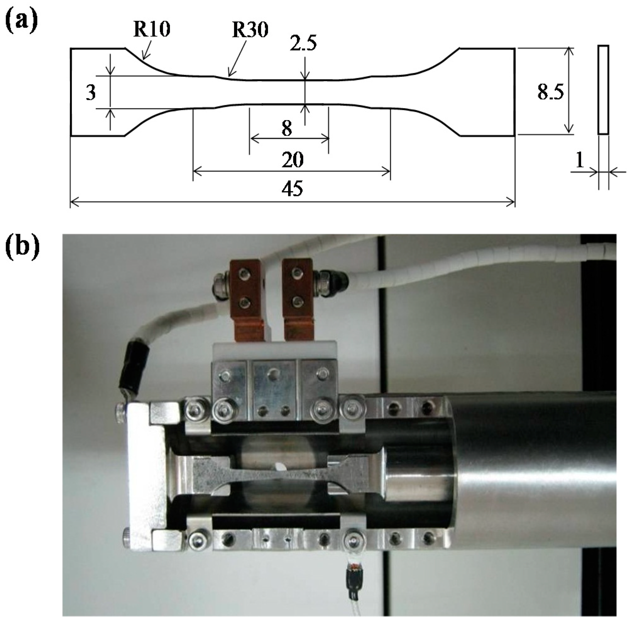
2. Materials and Methods

The cast CDSS materials being studied were centrifugal casting Z3CN20-09M (similar to CF3) steel cut from the primary coolant water pipe in Daya Bay Nuclear Power Plant. The materials were thermally aged at 400 °C for as long as 20,000 h to simulate the behavior of CDSS after long-term operation at real service temperatures. The aging time at service temperatures, corresponding to the accelerated thermal aging experiment at 400 °C, can be calculated using an Arrhenius extrapolation [4]. In this study, the accelerated thermal aging at 400 °C for 3000 and 20,000 h was equal to real service at 290 °C for 11.0 and 73.2 years, respectively, using an activation energy of 100 kJ∙mol−1. The activation energy in Arrhenius’s equation is taken from the activation energy for Cr self-diffusion because the spinodal decomposition in ferrite is the primary mechanism of thermal aging embrittlement. Spinodal decomposition occurs at temperatures ranging from 250–500 °C, resulting in the Cr-rich and Cr-depleted domains by Cr segregation [6].
The studied CDSS has the compositions in wt.% of 20.12 Cr, 9.73 Ni, 1.04 Si, 0.96 Mn, 0.14 Mo, 0.033 C, 0.044 N, 0.014 P, 0.0009 S, and balance Fe. The microstructure of the as-cast material was observed using electron backscatter diffraction (EBSD) in an SEM (ZEISS Supra 55, Oberkochen, Germany). The EBSD sample was prepared by electropolishing with a 60 H3PO4:25 H2SO4:15 H2O solution.
The mechanical property changes during thermal aging were investigated by tensile tests and hardness tests. The hardness of both ferrite and austenite phases was studied by a Vickers hardness tester (Leica VMHT 30M, Wetzlar, Germany). A load of 25 g was used in the hardness tests to make sure that the indentation sizes were smaller than 10 μm in both phases. In addition, ferrite islands larger than 40 μm were selected in the hardness testing to avoid the soft substrate effect of austenite in the thermally aged specimen. Prior to hardness testing, the samples were ground with 2000-grit SiC papers, then mechanically polished using 1.5-grit diamond pastes, and finally etched by a ferric chloride solution (5g FeCl3 + 100 mL HCl + 100 mL CH3OH + 100 mL H2O).
An in situ observation of crack initiation and propagation in the long-term thermally aged CDSS was performed at room temperature in the vacuum chamber of the SEM, equipped with a specially designed servo-hydraulic testing system (SEM-SERVO 550, Shimadzu, Japan). The specimen geometry and the stage are shown in Figure 1. This sample was ground with 2000-grit SiC papers and then electropolished with a 60 H3PO4:25 H2SO4:15 H2O solution to distinguish ferrite from the austenite matrix after deformation. The in situ SEM tensile test was performed at room temperature using a normal strain rate of 1 × 10⁻⁴ s−1. During tensile loading, images were taken when the crack initiation and propagation appeared. The strains corresponding to these images were obtained by comparing the recording time of the images and the tensile loading data.
After the in situ tensile tests were performed, the fracture surface morphologies of both un-aged and aged samples were observed by SEM. The deformed microstructure of the long-term aged specimen was observed by a field-emission TEM (FEI Tecnai F20-ST, Eindhoven, The Netherlands) operated at 200 kV. The TEM specimen was cut near the tensile fracture and thinned by an FIB-SEM system (Zeiss Auriga, Oberkochen, Germany).

3. Results and Discussions

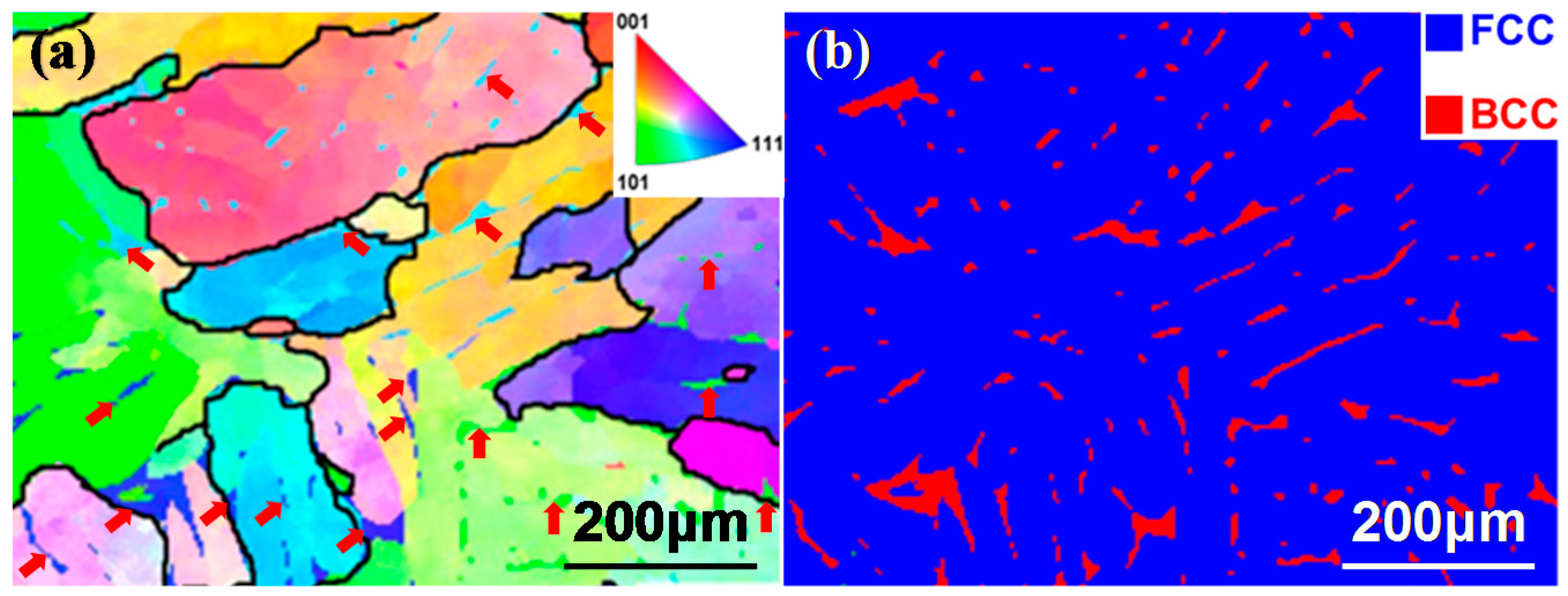
3.1. Microstructure Observation

The EBSD orientation map is shown in Figure 2a, and the insert depicts the orientation of each grain. The phase map, shown in Figure 2b, shows the duplex structure of austenite (blue) and ferrite (red). As a cast material, austenite in the present studied CDSS has a very large grain size of several hundred microns, and the ferrite islands with much smaller sizes distribute within the austenite matrix. The ferrite islands within different austenite grains may have the same orientation, which is marked by the arrows in the same directions in Figure 2a. The volume fraction of ferrite was evaluated as 12% using optical metallography.

3.2. Thermal-Aging-Induced Mechanical Property Changes

The tensile properties and hardness in both phases of the un-aged and long-term thermally aged steels are shown in Table 1. Both the yield strength (YS) and ultimate tensile strength (UTS) increased by approximately 15%, and the plasticity decreased by 21% after thermal aging at 400 °C for 20,000 h. Table 1 also lists the Vickers hardness of austenite and ferrite in both the un-aged and aged CDSS. For the un-aged specimen, both the austenitic and ferritic phases had almost the same hardness. After aging at 400 °C for 20,000 h, the hardness in austenite remained unchanged, but ferrite hardness had a drastic increase of approximately 140%. This indicates that the increase in strength and decrease in ductility of CDSS after thermal aging is closely related to the severe hardening in ferrite.
The impact properties, hardness, and tensile properties of the CDSS during thermal aging were studied in our previous study, and we found that the impact energy and the hardness in ferrite significantly changed in the early stage and then became saturated, while the tensile properties had no such dramatic change after thermal aging [3,22]. Although the mechanical properties of the material aged for 3000 h were similar to those of materials aged for 20,000 h, the cleavage facets of the brittle ferrite phases were only observed on the tensile fracture surface of the material thermally aged for 20,000 h, indicating that the behaviors of crack initiation and propagation in the material aged for 20,000 h are quite different to those of the materials aged for less time [22]. To observe the crack initiation and propagation in the long-term thermally aged material during tensile loading, the material aged for 20,000 h was selected to carry out this work using an in situ SEM.
Figure 3a,c shows the macroscopic and microscopic morphologies of the fracture surfaces of the un-aged specimen. The homogeneous distribution of fine dimples is a typical ductile fracture characteristic, indicating that there is no difference in the deformation ability of ferrite and austenite in the un-aged CDSS. In stark contrast, the fracture surfaces of the long-term thermally aged specimen show the mixed features of brittle cleavages in ferrite and ductile shearing in austenite, as shown in Figure 3b,d. As cleavage is the mechanism of brittle trans-granular fracture, and occurs through the cleaving of the crystals along crystallographic planes, the appearance of typical cleavage facets are the flat areas on the fracture surface. Therefore, the brittle cleavage areas can be easily distinguished from the other areas by their flat feathers, as shown in Figure 3d, marked by dashed lines. Hardening in ferrite caused by thermal aging is considered to destroy the deformation compatibility between the two phases in CDSS. The deterioration of plastic deformation capacity during the aging process makes ferrite prone to brittle fracture.

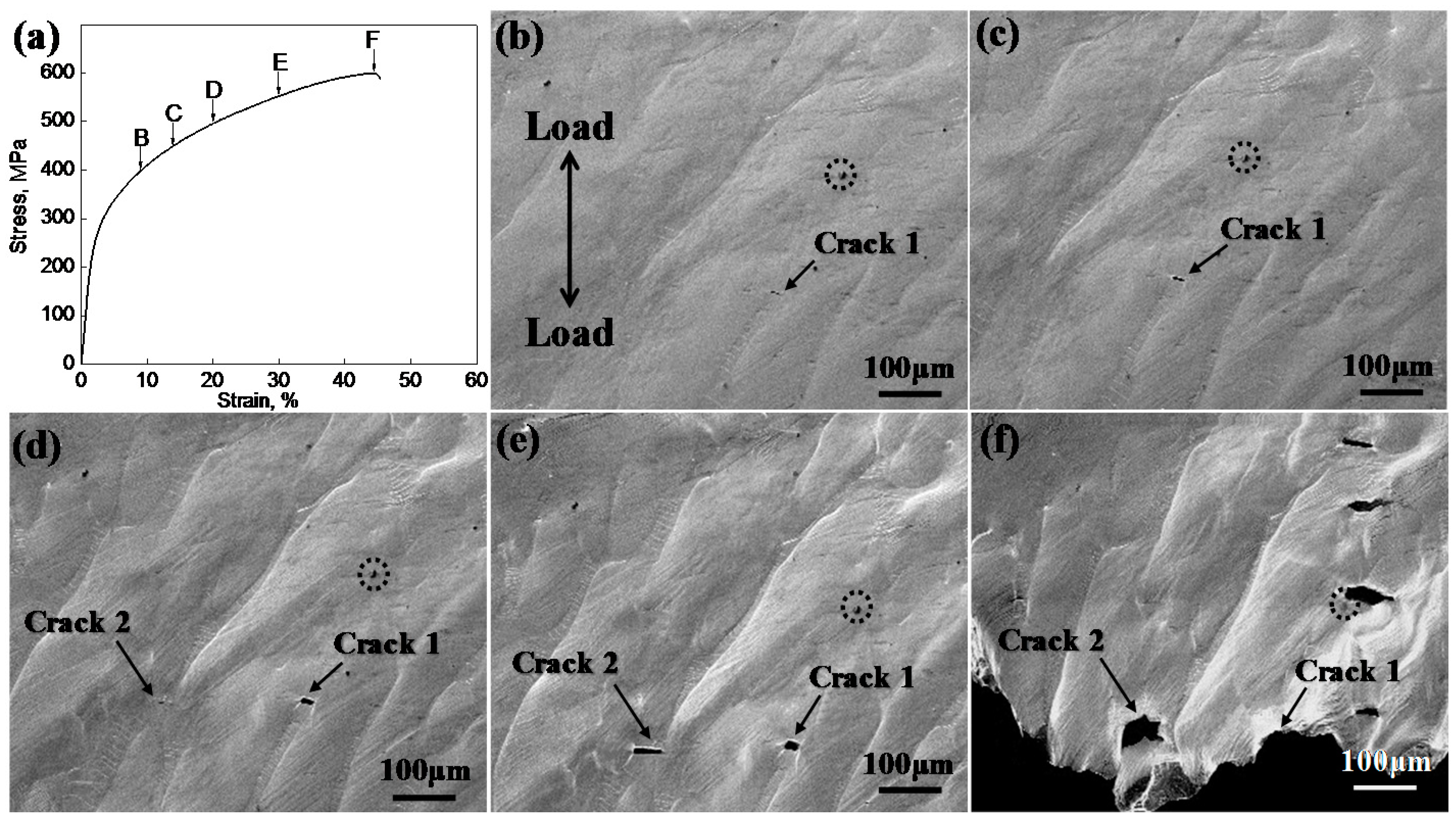
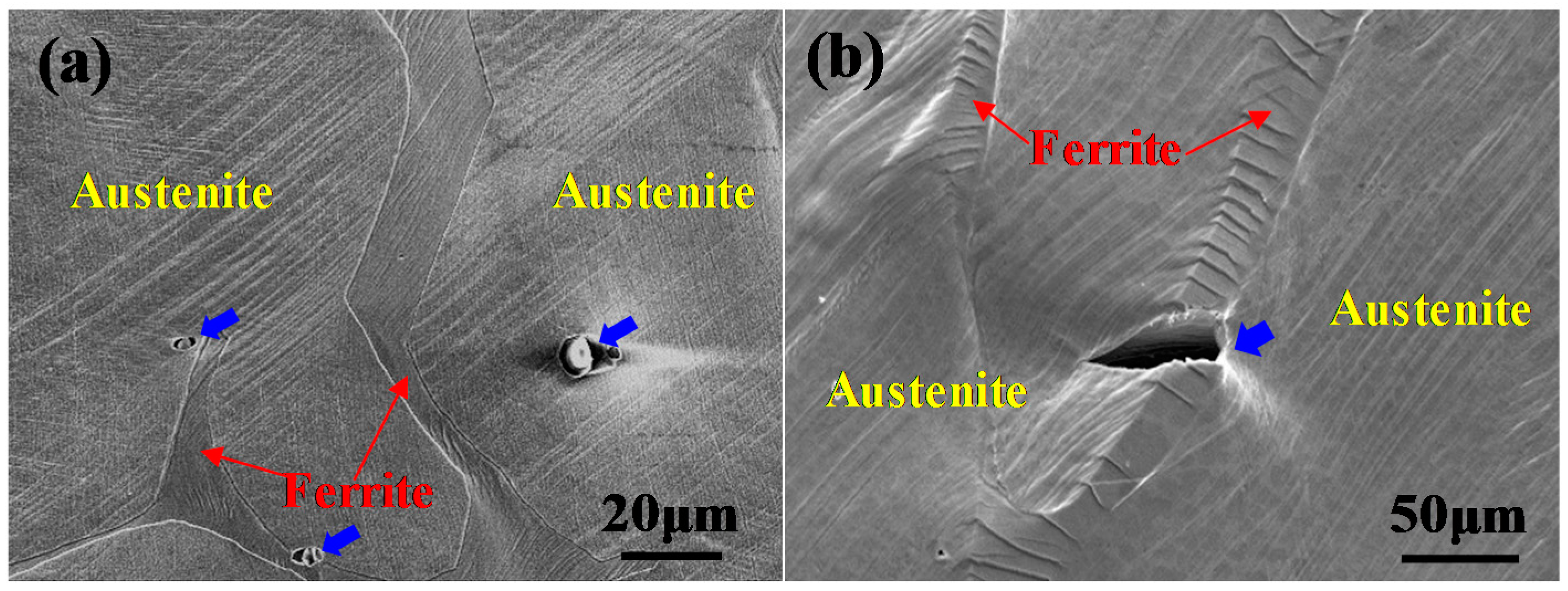
3.3. In Situ SEM Observation of Crack Initiation in the Aged CDSS

In situ SEM observation during tensile loading was conducted in the long-term thermally aged CDSS and the microstructural evolution is shown in Figure 4. Some images are selected at specific strains (9%, 14%, 20%, 30%, and rupture, corresponding to B, C, D, E, and F in Figure 4a, respectively) to show the stages of crack initiation, propagation, and final rupture.
At the stage of low strain, no visible plastic deformation features were observed. Both ferrite and austenite appeared to be flat and smooth, and the two phases could not be distinguished from each other. When strain increased to 9%, deformation characteristics could be seen (as in Figure 4b) and the ferrite phases became slightly concave. The first crack (marked as Crack 1) in the tensile process initiated in ferrite and propagated within the ferrite grain along the direction perpendicular to stress, as shown in Figure 4c. Although the ferrite phases become very brittle after long-term thermal aging, the fracture of ferrite underwent a two-step process of crack initiation and propagation. Long-strip ferrite phases could not complete fracture-like particles after the crack initiation. Further increases in strain caused another crack in ferrite (marked as Crack 2), as shown in Figure 4d; Crack 1 and Crack 2 were arranged in parallel. After long-term thermal aging, ferrite became brittle but austenite remained ductile. During tensile loading, the austenite matrix deformed easily and bore most of the plastic deformation. As the ferrite phases became brittle and hard to deform, the phase boundaries between austenite and ferrite accumulated more stress with increasing plastic deformation. When this concentrated stress exceeded the cleavage stress of ferrite, cracks formed in the brittle ferrite. The cracks in ferrite mainly formed in the B-C-D stage, as shown in Figure 4a, and this suggests that the critical cleavage fracture stress of ferrite in the long-term thermally aged CDSS was approximately 400–500 MPa.
After the cracks extended throughout the ferrite grains, the increase in stress pulled the cracks open and caused considerably greater stress on the phase boundaries of ferrite and austenite, as shown in Figure 4e. The preferential propagation path of the primary crack for the thermally aged CDSS linked the prior cracks in ferrite. As seen from the surface morphologies after rupturing in Figure 4f, these prior cracks (e.g., Crack 1 and 2) were very close to the fracture surface.

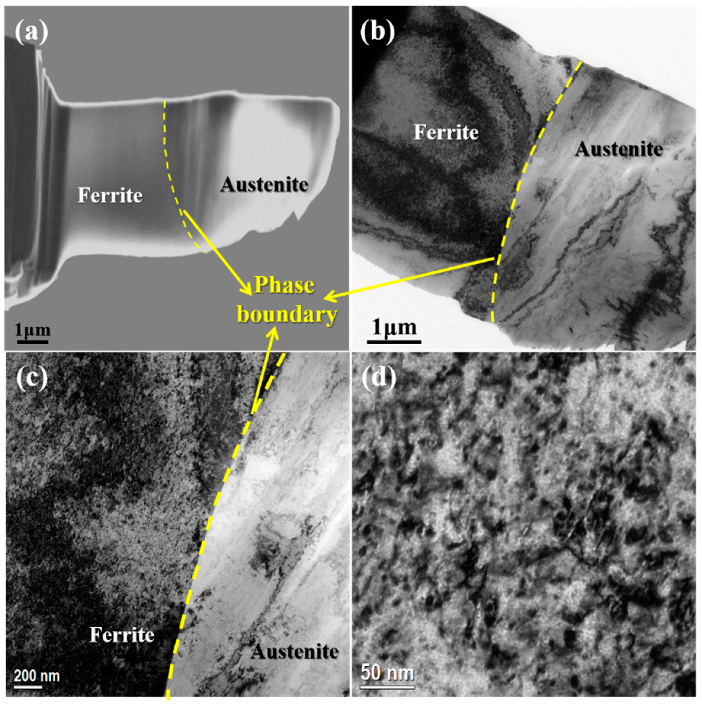
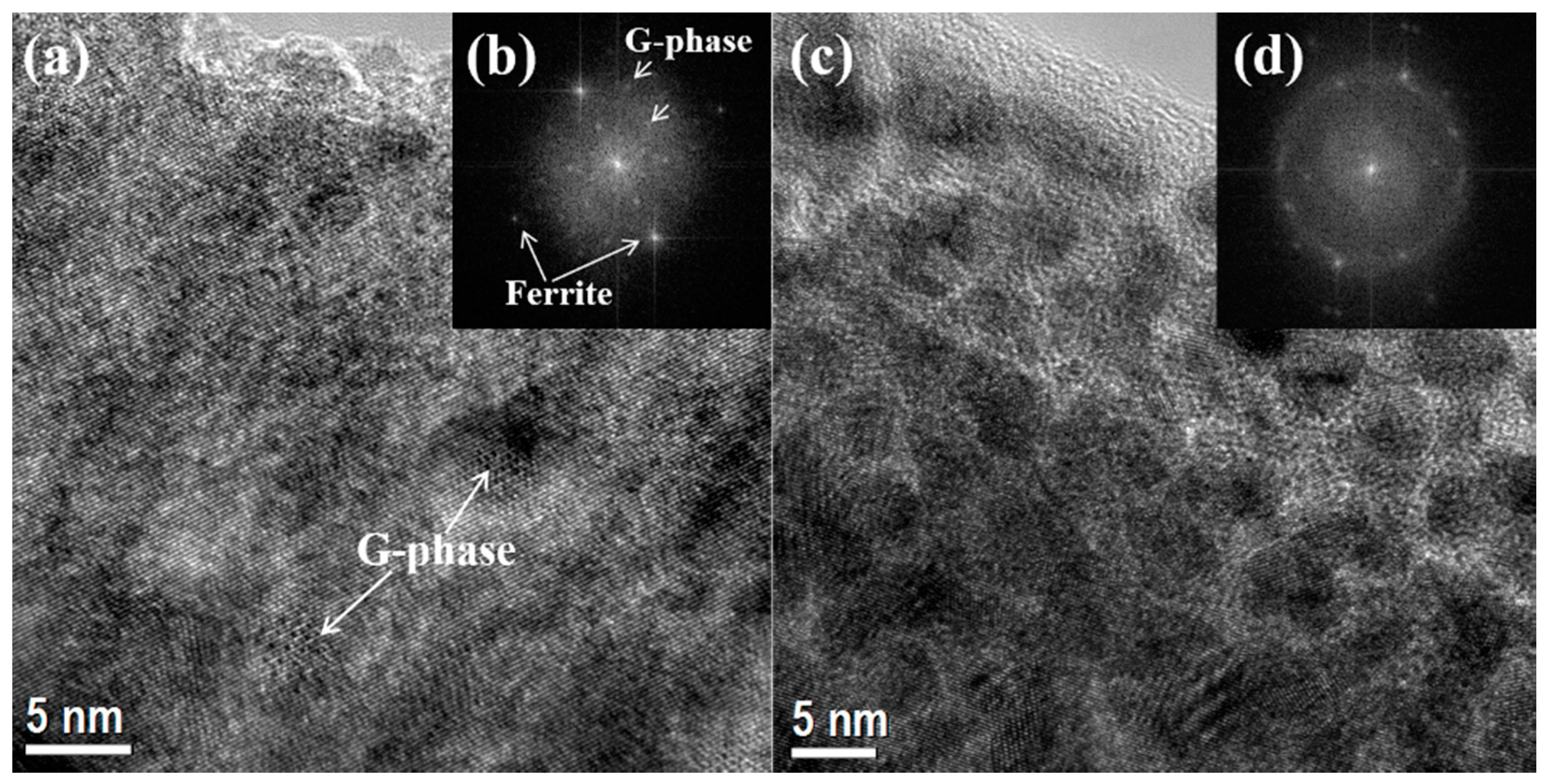
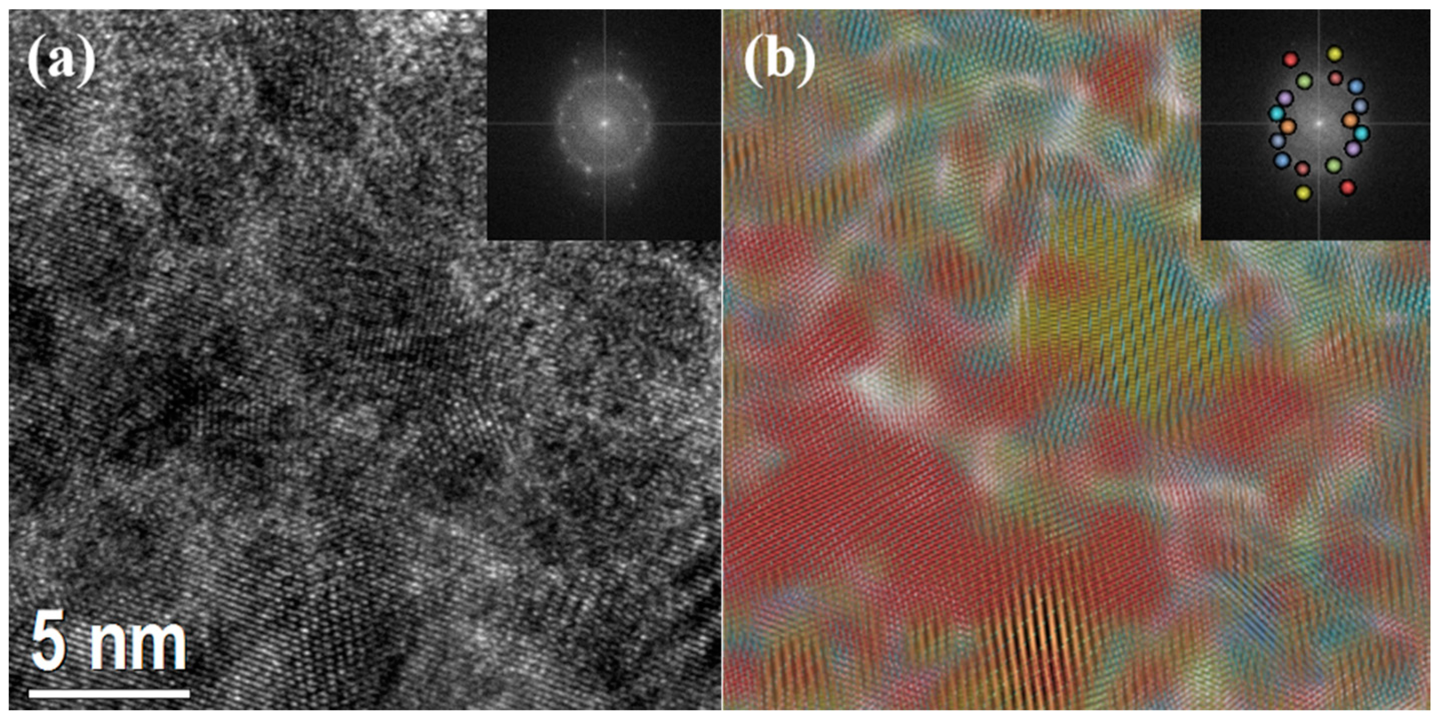
3.4. TEM Observation of Deformed Microstructures in the Aged CDSS

The transition from ductile to brittle in ferrite of the aged CDSS, as well as its severe hardening, is caused by nanoscale metallurgical reactions, including spinodal decomposition and G-phase precipitation in ferrite, which were systematically characterized by Atom probe tomography (APT) and TEM in our previous research [3,18,23]. The deformed microstructures of the aged CDSS were observed by TEM, which enabled us to study the interactions between these precipitates and dislocations. The TEM foil of the long-term thermally aged material was prepared by an FIB system from the tensile sample near the fracture. This TEM sample contained both ferrite and austenite, and the SEM and TEM images of the overall morphology are shown in Figure 5a,b. There was no precipitation and only a few dislocations in austenite, as shown in Figure 5c. By contrast, intensive precipitates and dislocations were observed in ferrite. The dislocation-precipitate interactions (Figure 5d) indicate that the dislocation motion is hindered, which makes ferrite in the aged CDSS hard and brittle.
The ferrite morphologies in the undeformed and deformed steel that were thermally aged at 400 °C for 20,000 h were observed and compared by HRTEM, as shown in Figure 6. G-phases can be clearly observed in the HRTEM image and the corresponding fast Fourier transform (FFT) patterns, as shown in Figure 6a,b. However, in the ferrite of the deformed sample, G-phases cannot easily be distinguished from Figure 6c,d.
It is well known that ferrite spinodally decomposes into coherent Cr-enriched and Cr-depleted domains after long-term thermal aging [2,3,4,7,8,9]. As the modulated structures had very close lattice parameters, showing the continuity of the crystal lattices, as in Figure 6a, they could not be distinguished by TEM or HRTEM. APT has been widely used to characterize the spinodal decomposition in Fe-Cr alloys and ferrite in CDSS, and the average size of the Cr-enriched and Cr-depleted domains was estimated to be approximately 7 nm for CDSS that was thermally aged for 20,000 h [18]. The Young’s modulus and shear modulus of pure Cr are higher than those of pure iron, and in the alloys they increase with increasing Cr content [19]. The different moduli between Cr-enriched and Cr-depleted domains caused deformation incompatibility on the nanometer scale, forming many regions with different orientations, as shown in Figure 6c,d.
The lattice images of the special direction can be obtained by filtering in the corresponding FFT patterns. The region of the lattice image and its corresponding FFT pattern from the same orientation were marked in the same color, as shown in Figure 7. These regions with different orientations formed under severe deformation in the tensile process, and they had almost the same dimension as the spinodal structures of Cr-enriched and Cr-depleted domains.

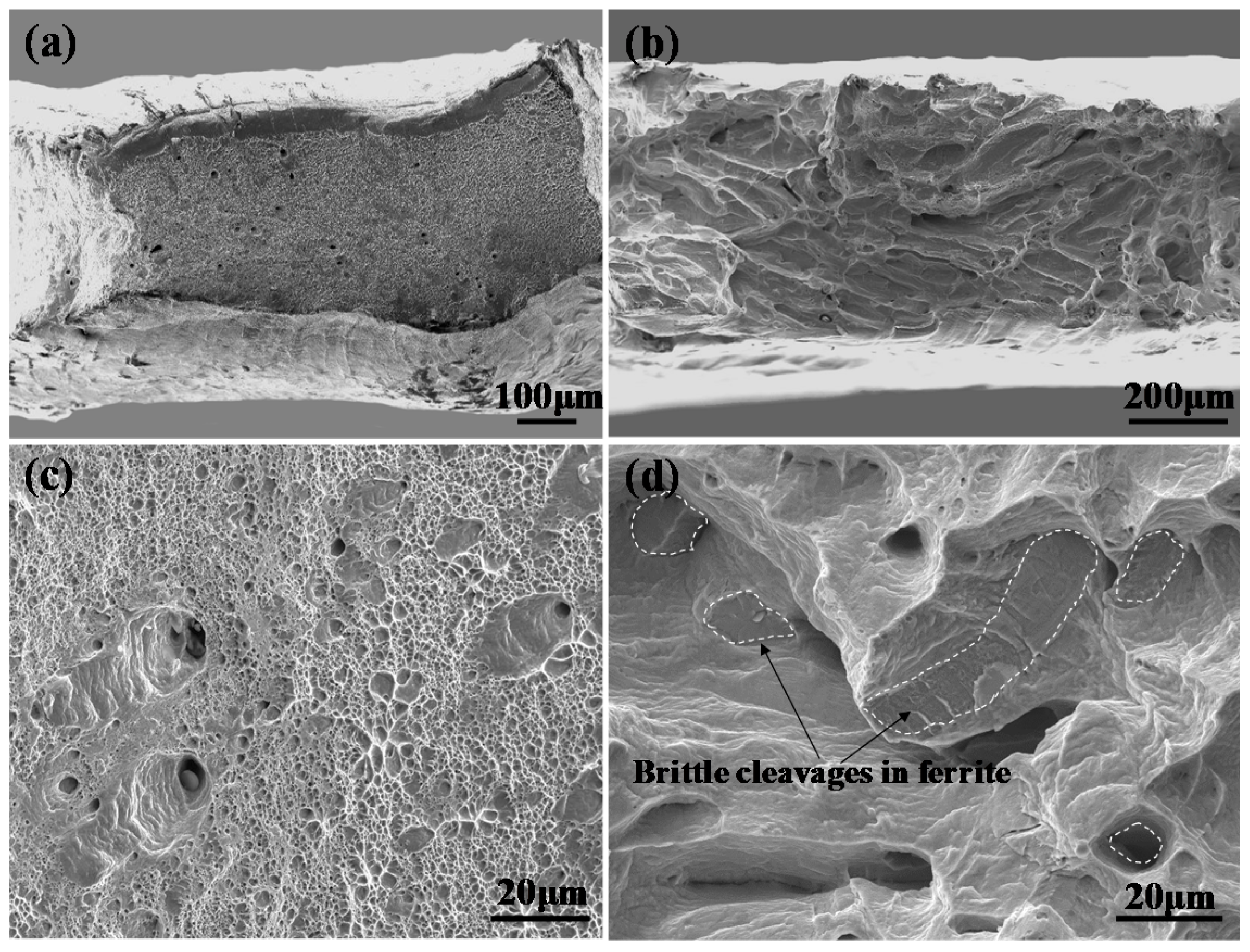
3.5. Fracture Mechanism of the Thermally Aged CDSS

After in situ SEM tensile testing, the surface morphologies of the fractured samples were also observed by SEM to investigate the crack propagation process. As shown in Figure 8a, the two phases of ferrite and austenite in the un-aged CDSS had almost the same deformation features, indicating that they had similar deformation ability. Voids initiated at inclusions, marked by solid arrows in Figure 8a, and their growth and coalescence led to ductile fracture. The halves of these voids are represented as dimples on the fracture surface, as shown in Figure 3a.
For the aged CDSS, the in situ SEM results showed the initiation and propagation of cracks within ferrite. Figure 8b shows the further extension of cracks from ferrite to austenite. The stress was released when the crack propagated throughout the ferrite grain. When the propagation of the crack encountered a phase boundary, stress concentrated on this phase boundary (marked by a solid arrow in Figure 8b), and caused the beginning of cracks in austenite. With increasing applied stress, a large number of cracks grew into austenite. When some of these cracks were connected to each other, a primary crack formed, which further caused the rupture of the aged CDSS.
After long-term thermal aging, the ferrite in CDSS decomposed into two kinds of coherent and interconnected regions with different chemical compositions and mechanical properties. Due to the deformation incompatibility of these domains, dislocations in ferrite were severely hampered, resulting in the reduction of plastic deformation ability. When the stress concentration in ferrite rose to a certain level, the initiation and propagation of cracks occurred throughout the ferrite. The local stress was released when the crack propagated throughout the ferrite grain. Further extension of the crack in ferrite was hindered by the phase boundary where the stress was most concentrated, which caused the initiation of cracks in austenite. The prior fracture of ferrite accelerated the shearing of austenite and reduced the plasticity of the thermally aged CDSS.

4. Conclusions

The in situ SEM technique was used to investigate the deformation and fracture behavior of long-term thermally aged duplex stainless steel. After thermal aging at 400 °C for 20,000 h, the yield stress and ultimate tensile stress of CDSS exhibited a small increase, while the tensile fracture changed from ductile to brittle. Hardening in ferrite was caused by the spinodal decomposition into coherent and interconnected regions with different chemical compositions and mechanical properties. The deformation incompatibility of Cr-enriched and Cr-depleted domains resulted in the concentration of stress and the initiation and propagation of cracks in ferrite. The initial cracks first propagated throughout the ferrite grains and then generated stress concentrates on the phase boundaries, which caused the initiation of cracks in austenite. The aged CDSS finally ruptured by connecting these pre-existing cracks in ferrite.

Author Contributions

X.W. and Y.W. designed the research project; S.L. performed the experiments, analyzed the data, and wrote the manuscript; all the authors contributed to the discussions and commented on the manuscript.

Funding

This work was financially supported by the National Natural Science Foundation of China (NSFC) (Grant No. 51601013) and the State Key Laboratory for Advanced Metals and Materials (Grant No. 2018Z-25).

Conflicts of Interest

The authors declare no conflict of interest.

References

  1. Chung, H.M. Aging and life prediction of cast duplex stainless steel components. Int. J. Pres. Vessels Pip. 1992, 50, 179–213. [Google Scholar] [CrossRef]
  2. Pareige, C.; Novy, S.; Saillet, S.; Pareige, P. Study of phase transformation and mechanical properties evolution of duplex stainless steels after long term thermal ageing (>20 years). J. Nucl. Mater. 2011, 411, 90–96. [Google Scholar] [CrossRef]
  3. Li, S.L.; Wang, Y.L.; Zhang, H.L.; Li, S.X.; Zheng, K.; Xue, F.; Wang, X.T. Microstructure evolution and impact fracture behaviors of Z3CN20-09M stainless steels after long-term thermal aging. J. Nucl. Mater. 2013, 433, 41–49. [Google Scholar] [CrossRef]
  4. Kawaguchi, S.; Sakamoto, N.; Takano, G.; Matsuda, F.; Kikuchi, Y.; Mráz, L. Microstructural changes and fracture behavior of CF8M duplex stainless steels after long-term aging. Nucl. Eng. Des. 1997, 174, 273–285. [Google Scholar] [CrossRef]
  5. Chen, Y.; Alexandreanu, B.; Chen, W.Y.; Natesan, K.; Li, Z.; Yang, Y.; Rao, A.S. Cracking behavior of thermally aged and irradiated CF-8 cast austenitic stainless steel. J. Nucl. Mater. 2015, 466, 560–568. [Google Scholar] [CrossRef] [Green Version]
  6. Chandra, K.; Singhal, R.; Kain, V.; Raja, V.S. Low temperature embrittlement of duplex stainless steel: Correlation between mechanical and electrochemical behavior. Mater. Sci. Eng. A 2010, 527, 3904–3912. [Google Scholar] [CrossRef]
  7. Yamada, T.; Okano, S.; Kuwano, H. Mechanical property and microstructural change by thermal aging of SCS14A cast duplex stainless steel. J. Nucl. Mater. 2006, 350, 47–55. [Google Scholar] [CrossRef]
  8. Shiao, J.J.; Tsai, C.H.; Kai, J.J.; Huang, J.H. Aging embrittlement and lattice image analysis in a Fe-Cr-Ni duplex stainless steel aged at 400 °C. J. Nucl. Mater. 1994, 217, 269–278. [Google Scholar] [CrossRef]
  9. Timofeev, B.T.; Nikolaev, Y.K. About the prediction and assessment of thermal embrittlement of Cr–Ni austenitic–ferritic weld metal and castings at the ageing temperatures 260–425 °C. Int. J. Pres. Vessels Pip. 1999, 76, 849–856. [Google Scholar] [CrossRef]
  10. Miller, M.K.; Russell, K.F. Comparison of the rate of decomposition in Fe-45% Cr, Fe-45% Cr-5% Ni and duplex stainless steels. Appl. Surf. Sci. 1996, 94, 398–402. [Google Scholar] [CrossRef]
  11. Chung, H.M.; Leax, T.R. Embrittlement of laboratory and reactor aged CF3, CF8, and CF8M duplex stainless steels. Mater. Sci. Tech. Lond. 1990, 6, 249–262. [Google Scholar] [CrossRef]
  12. Lo, K.H.; Shek, C.H.; Lai, J.K.L. Recent developments in stainless steels. Mater. Sci. Eng. R 2009, 65, 39–104. [Google Scholar] [CrossRef]
  13. Chandra, K.; Kain, V.; Bhutani, V.; Raja, V.S.; Tewari, R.; Dey, G.K.; Chakravartty, J.K. Low temperature thermal aging of austenitic stainless steel welds: Kinetics and effects on mechanical properties. Mater. Sci. Eng. A 2012, 534, 163–175. [Google Scholar] [CrossRef]
  14. Takeuchi, T.; Kameda, J.; Nagai, Y.; Toyama, T.; Matsukawa, Y.; Nishiyama, Y.; Onizawa, K. Microstructural changes of a thermally aged stainless steel submerged arc weld overlay cladding of nuclear reactor pressure vessels. J. Nucl. Mater. 2012, 425, 60–64. [Google Scholar] [CrossRef]
  15. Li, S.L.; Zhang, H.L.; Wang, Y.L.; Li, S.X.; Zheng, K.; Xue, F.; Wang, X.T. Annealing induced recovery of long-term thermal aging embrittlement in a duplex stainless steel. Mater. Sci. Eng. A 2013, 564, 85–91. [Google Scholar] [CrossRef]
  16. Danoix, F.; Auger, P. Atom probe studies of the Fe-Cr system and stainless steels aged at intermediate temperature: A review. Mater. Charact. 2000, 44, 177–201. [Google Scholar] [CrossRef]
  17. Danoix, F.; Auger, P.; Blavette, D. Hardening of aged duplex stainless steels by spinodal decomposition. Microsc. Microanal. 2004, 10, 349–354. [Google Scholar] [CrossRef]
  18. Zhang, B.; Xue, F.; Li, S.L.; Wang, X.T.; Liang, N.N.; Zhao, Y.H.; Sha, G. Non-uniform phase separation in ferrite of a duplex stainless steel. Acta Mater. 2017, 140, 388–397. [Google Scholar] [CrossRef]
  19. Jia, N.; Peng, R.L.; Brown, D.W.; Clausen, B.; Wang, Y.D. Tensile deformation behavior of duplex stainless steel studied by In-Situ Time-of-Flight neutron diffraction. Metall. Mater. Trans. A 2008, 39, 3134–3140. [Google Scholar] [CrossRef]
  20. Hazarabedian, A.; Marini, B. Quantification of damage progression in a thermally aged duplex stainless steel. Mater. Res. 2002, 5, 113–117. [Google Scholar] [CrossRef]
  21. Hazarabedian, A.; Forget, P.; Marini, B. Local approach to fracture of an aged duplex stainless steel. Mater. Res. 2002, 5, 131–135. [Google Scholar] [CrossRef]
  22. Li, S.; Wang, Y.; Li, S.; Zhang, H.; Xue, F.; Wang, X. Microstructures and mechanical properties of cast austenite stainless steels after long-term thermal aging at low temperature. Mater. Des. 2013, 50, 886–892. [Google Scholar] [CrossRef]
  23. Li, S.; Wang, Y.; Wang, X.; Xue, F. G-phase precipitation in duplex stainless steels after long-term thermal aging: A high-resolution transmission electron microscopy study. J. Nucl. Mater. 2014, 452, 382–388. [Google Scholar] [CrossRef]
Figure 1. (a) The tensile specimen geometry; (b) the stage for in situ SEM observation (unit: mm).
Metals 09 00258 g001
Figure 2. (a) Electron backscatter diffraction (EBSD) orientation map, with the insert showing the orientation of each grain; (b) phase map of the studied steel.
Metals 09 00258 g002
Figure 3. (a,c) Macroscopic and microscopic morphologies of the fracture surface of the un-aged CDSS (b,d) and of the long-term thermally aged CDSS.
Metals 09 00258 g003
Figure 4. (a) In situ observation at different stages for strains (b) ε = 9%; (c) 14%; (d) 20%; (e) 30%; and (f) rupture of CDSS thermally aged at 400 °C for 20,000 h. An inclusion is marked by a dashed circle as the position mark.
Metals 09 00258 g004
Figure 5. (a) SEM and (b) TEM images of the overall morphology; (c) TEM images of the phase boundary and (d) ferrite near the tensile fracture in the thermally aged CDSS.
Metals 09 00258 g005
Figure 6. (a) HRTEM images of ferrite in the undeformed and (c) deformed samples of the steels thermally aged at 400 °C for 20,000 h. (b) and (d) are the corresponding FFT patterns of (a) and (c), respectively.
Metals 09 00258 g006
Figure 7. (a) HRTEM image and (b) the corresponding orientation distribution of ferrite in the deformed steel that was thermally aged at 400 °C for 20,000 h.
Metals 09 00258 g007
Figure 8. Deformation characteristics of austenite and ferrite phases near the tensile fracture of the (a) un-aged and (b) aged specimens.
Metals 09 00258 g008
Table 1. Tensile properties and hardness in the un-aged and aged cast duplex stainless steel (CDSS).
MaterialsTensile PropertiesVickers Hardness, HV
Yield Strength YS (MPa)Ultimate Tensile Strength UTS (MPa)Elongation (%)AusteniteFerrite
Un-aged237.4523.554.6217.1 ± 17.2230.1 ± 8.9
Aged for 3000 h288.3674.940.1211.6 ± 13.5468.7 ± 20.9
Aged for 20,000 h230.7599.844.1201.3 ± 10.8556.4 ± 71.9

