Abstract
Although the joining of aluminum and copper is a difficult task, several studies have shown that friction stir welding (FSW) is capable of producing aluminum-copper-joints with excellent performance. Therefore, it is desirable to use this joining technique for the production of cost- and weight-reduced conductors for the automotive sector. The exposed copper contact spots in automobiles are usually coated with tin for design reasons and in order to improve their corrosion resistance. In this context, it is possible to perform the weld at first and to coat afterwards, or to weld already coated copper workpieces. Taking this into account, this paper presents results on the influence of copper-sided tinning on the joint formation as well as the achievable mechanical and electrical properties of friction stir butt welded aluminum-copper joints. Two variants were considered. The first variant included copper blanks with a tinned surface. For the second variant the surface and the abutting edge of the copper were coated. The best welds achieved excellent electrical properties and their tensile strength was only slightly reduced compared to the aluminum base material. Thus, it was shown that if these tensile strength losses are acceptable, FSW of aluminum to tin coated copper is applicable.
1. Introduction
In the state of the art, copper and copper-based materials are increasingly used for electrical components. Excellent thermal and electrical conductivity combined with high ductility, creep resistance and corrosion resistance make it a highly preferable choice when it comes to choose an adequate material for current-carrying elements. On the other hand, its high density and procurement costs make it desirable to find an alternative in order to create efficient lightweight products at a low price [1,2,3].
In this context, dissimilar joints of aluminum and copper come to attention, because they provide the opportunity to combine both the advantages of copper with the lower density and material costs of the aluminum [4]. For an efficient way to exploit these potentials, it is necessary to find an effective way to produce dissimilar joints between aluminum and copper. Previous studies in this field have shown, that firmly bonded joints result in a lower electrical resistance than interlocking or force-locking methods [5]. It is also known, that conventional fusion welding is disadvantageous due to the different mechanical and physical properties of the base materials such as different melting temperatures, the high thermal conductivities and the low mutual solubility which leads to the formation of brittle and highly resistive intermetallic phases [6,7,8,9].
Friction stir welding (FSW) was found to be a suitable alternative for producing dissimilar joints between aluminum and copper [10,11,12]. In this process, which was patented in 1991 by Wayne Thomas at TWI, a rotating tool was inserted into the joint gap and traversed along the joint edge [13,14]. The tool is usually cylindrical and consists of a shoulder and pin, which plasticize and stir the material [15]. The temperatures during the process do not reach the melting temperatures of the base materials, so that the formation of intermetallic phases is reduced compared to fusion welding since intermetallic phase formation during solidification from the liquid phase is prevented [16]. In previous studies, the influence of welding parameters and the arrangement of the two materials in the process were investigated. Research studies from Xue et al. [17] and Akinlabi [18] have shown, that positioning the harder copper on the advancing side (AS) of the tool and the softer aluminum on the retreating side (RS) can improve the results so that defect-free joints with better mechanical and microstructural properties are achieved. In addition, an offset towards the softer aluminum is recommended to achieve a better material flow [17].
As far as the authors of this study know, there is currently no series application in the automotive industry to produce aluminum-copper joints for electrical contacts by means of friction stir welding. In this regard, several aspects require further investigations. The aim of this study is to investigate the influence of a copper-sided tin coating on the weldability and the joint formation for FSW of aluminum and copper. This is of interest since exposed copper contact spots in automotive applications are usually tin-coated for design reasons and in order to improve their corrosion behavior. In this context, it is possible to perform the weld at first and to coat afterwards, or to weld already coated copper workpieces. Based on the investigations carried out, an order of process steps will be proposed.
2. Materials and Methods
In this study, blanks of aluminum EN AW-1050A and copper EN CW004A were friction stir butt welded. Dimensions of the blanks were 160 mm, 100 mm, and 3 mm (length, width, thickness). The chemical compositions of the base materials used are given in Table 1.

Table 1.
Chemical compositions of the applied base materials [19,20].
Prior to friction stir welding, a galvanic plating layer of matte tin with a minimum thickness of 9 µm was applied to the copper blanks. Position-controlled FSW was carried out on a PTG Powerstir portal system (PTG Heavy Industries Ltd, West Yorkshire, UK). The welding tool used was made of heat-treated steel (X40CrMoV5-1) and had a shoulder 18 mm in diameter and an unthreaded pin 6 mm in diameter and 2.9 mm in length.
Within the present study, two different variants were considered. In the first variant, the abutting edge of the copper workpiece was equal to the cutting edge, so that the tin was only on the surface. Within the second variant, the surface of the copper workpiece and also the abutting edge was coated with tin. Based on the results of a preliminary parametric investigation on uncoated joining partners, the results of which are given in [21], welding experiments with the optimum process parameters for the uncoated blanks were performed. The optimum welding parameters for uncoated sheets are given in Table 2. Using these welding parameters for the uncoated joining partners, the friction stir welds achieved tensile strength values at the level of the aluminum base material and failure occurred in the weaker aluminum.
Table 2.
Optimum friction stir welding parameters for uncoated blanks determined by a preliminary parametric investigation.
Tin has a melting point of 232 °C, while aluminum melts at 660 °C and copper at 1084 °C [22]. Since FSW is usually carried out at temperatures of two-thirds of the melting point of the lower-melting joining partner, melting of the tin coating and thus altered friction conditions were expected. Thus, the optimum parameter settings for non-coated sheets do not necessarily correspond to the optimum parameters for friction stir welds with tinned copper sheets. Therefore, welding tests with variation of welding parameters were carried out. The parameters traverse speed and tool rotation speed were varied using a full factorial design. The other process parameters listed in Table 2 were kept constant during the welding experiments. The variation of the parameters traverse speed and tool rotation speed was examined more closely, since these parameters significantly influenced the heat input during friction stir welding. The heat input between different welds was compared using the ratio between tool rotation speed and traverse speed (n/v-ratio). The n/v-ratio allowed a rough estimation of the heat input into the joining partners, since it indicated the number of revolutions of the welding tool per mm feed [23]. High heat input was represented by a high n/v-ratio and a low n/v-ratio stands for low heat input into the joining partners. Table 3 shows the full factorial experimental plan for the friction stir welding experiments. Three samples were welded for each parameter combination for statistical purposes.
Table 3.
Full factorial experimental plan for welding experiments for aluminum with tin coated copper.
The joint quality for the each parameter combination was evaluated by means of tensile testing and electrical resistance measurement. Furthermore, metallographic analyses were carried out on selected samples by means of digital microscopy and scanning electron microscopy (SEM). In order to have enough material available to detach a sufficient number of samples, the friction stir welds had a length of 120 mm.
Tensile testing was carried out according to DIN EN ISO 25239-5 [24] using a Zwick Z100 test machine (Zwick GmbH & Co. KG, Ulm, Germany) at an operating speed of 10 mm/min. Transversal sections of the joints were taken by water jet cutting for evaluation of the mechanical joint quality. While DIN EN ISO 25239-5 specifies a minimum distance of 50 mm from the plunging spot for detaching the tensile specimens, a distance of 20 mm has been set in order to avoid excessive material consumption [24]. The geometry of the tensile specimens corresponded to the specifications of DIN EN ISO 4136 [25]. In addition to the welded joints, five specimens were tensile tested for each material.
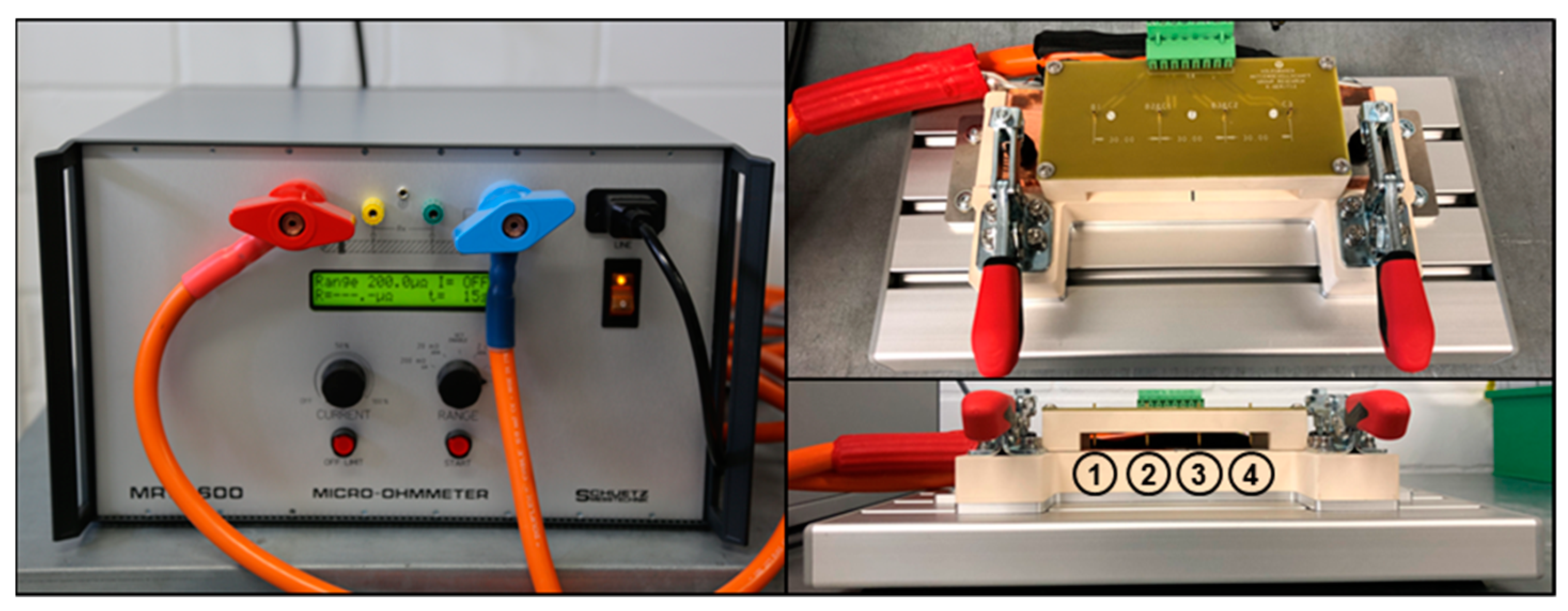
The analysis of the electrical joint quality was carried out using the four-point resistance measurement setup shown in Figure 1. The rectangular specimens for electrical resistance measurement were 190 mm in length and 40 mm in width. Micro-Ohmmeter MR5 – 600 (Schuetz Messtechnik GmbH, Teltow, Germany) was used to introduce the test current of 200 A, and to measure the electrical resistances of the weld seam and both base materials. A clamping system was built to fix the specimen to position the measuring tips accurately. The four measuring tips were arranged equidistantly with 30 mm to each other. The friction stir welded seam was measured via tips 2 and 3. The copper base material was arranged between tips 1 and 2 and the aluminum base material was analyzed via tips 3 and 4. 10 values were recorded and averaged subsequently for each of the three areas.

Figure 1.
Setup for electrical resistance measurement.
Standard metallographic procedures were used to prepare samples for digital microscopy. The preparation included mounting as well as manual grinding and polishing using 1200 SiC abrasive paper, 1 µm aluminum oxide suspension and 50 nm colloidal silica suspension. Manual grinding and polishing helped to avoid shifting of the soft aluminum material into the copper side. In order to analyze the macroscopic features of the welds, a digital microscope VHX-2000 (Keyence Deutschland GmbH, Neu-Isenburg, Germany) was used.
For further understanding of the joint formation, a scanning electron microscope model Scios (Field Electron and Ion Company, Hillsboro, OR, USA) was used. Backscattered electron (BSE) images were taken at an acceleration voltage of 5 kV and planar energy dispersive X-ray spectroscopy (EDX) analysis were carried out at an acceleration voltage of 20 kV. Prior to scanning electron microscopy, the samples were ground with 1200 and 2400 SiC abrasive papers and then polished with 6 µm, 3 µm and 1 µm diamond suspension. This preparation method helped to avoid topographical differences at the interfaces between Al and Cu and thus allowed to analyze the relevant areas properly.
3. Results and Discussion
3.1. Mechanical Properties of the AlCu+Sn Friction Stir Welds
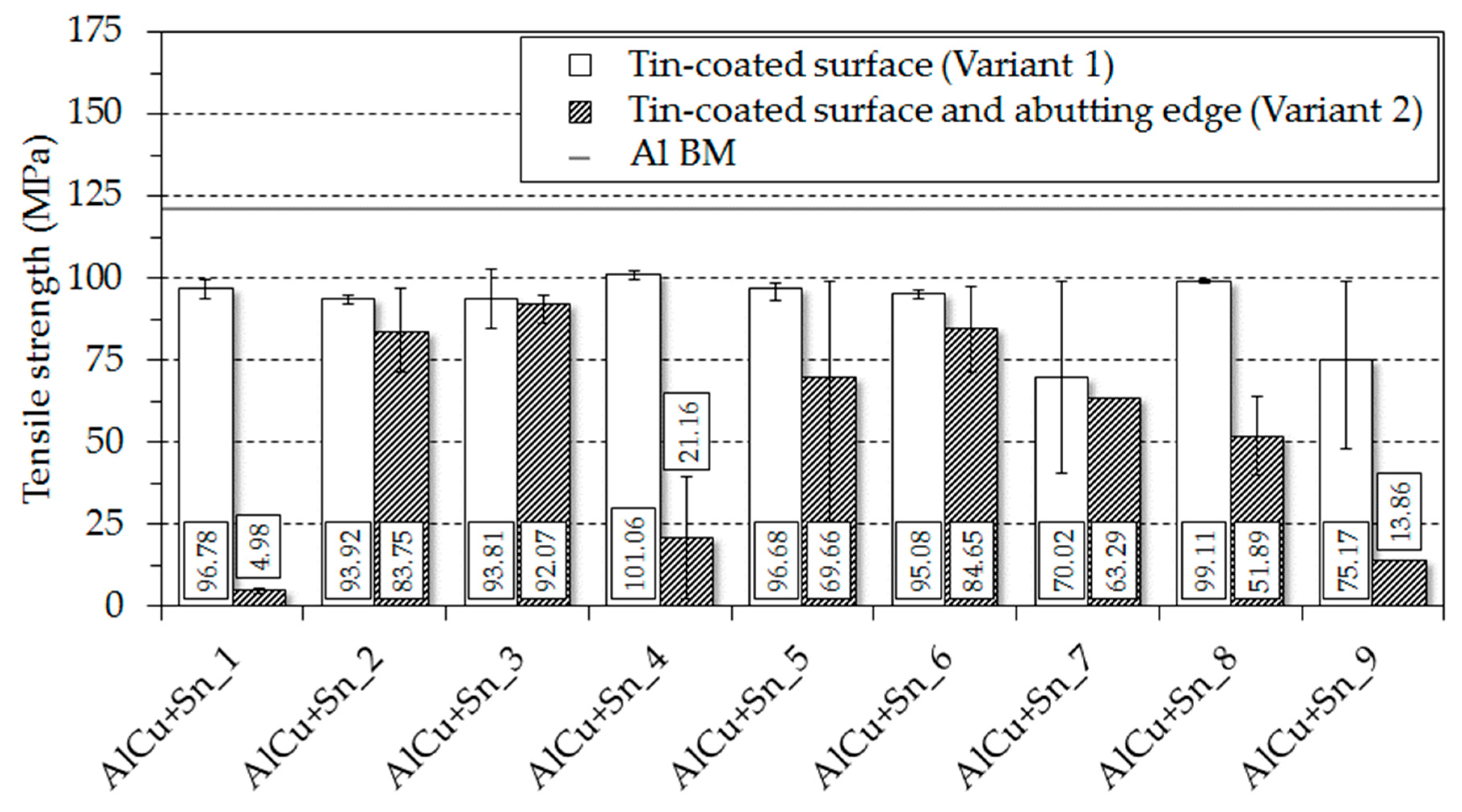
In order to evaluate the mechanical joint properties of the friction stir butt welds produced using aluminum and tinned copper blanks, tensile tests were carried out. The tensile test results for the two considered variants are given in Figure 2. From the diagram it follows that none of the examined parameter combinations, neither for the variant where the tin was only on the surface of the copper blanks (variant 1), nor for the variant where both the surface and the abutting edge were tinned (variant 2), achieved the tensile strength of the aluminum base material, which was found to be 120.69 MPa. For all tensile specimens tested, failure occurred either at the abutting edge or on the aluminum side in the stir zone. For variant 2, one specimen already broke during water jet cutting for parameter combinations AlCu+Sn_1, AlCu+Sn_4 and AlCu+Sn_8 and two specimens broke for parameter combinations AlCu+Sn_7 and AlCu+Sn_9, so that no tensile strength value could be determined here. On average, the joints made according to variant 1 were reduced in tensile strength by 24.4% compared to the aluminum base material, whereas the tensile strength reduction for friction stir welds produced according to variant 2 was 55.3%. However, the most powerful parameter sets AlCu+Sn_4 (variant 1) and AlCu+Sn_3 (variant 2) achieved 83.7% and 76.3% of the aluminum bae material strength, respectively. The most effective parameter set for variant 1 was equal to the optimum welding parameters for uncoated blanks with a n/v-ratio of 0.571/mm that were determined in the preliminary parametric investigation. On the other hand, the most effective parameter combination for variant 2 included a n/v-ratio of 1.51/mm, which resulted in a significantly higher heat input into the joint.
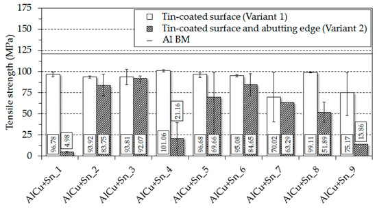
Figure 2.
Tensile test results for the friction stir welds produced using aluminum and tinned copper blanks.
It can be concluded that the joint strength was reduced by the presence of surface tin coating. An increasing tensile strength reduction could be observed if, in addition to the workpiece surface, the abutting edge of the copper blanks was tin-plated, too. Moreover, the deviations for the welds produced according to variant 2 were significantly higher than for friction stir welds made according to variant 1. Therefore, it is to be said that the reproducibility is affected negatively if, in addition to the surface of the copper blanks, the tinning is also applied to the abutting edge.
3.2. Electrical Properties of the AlCu+Sn Friction Stir Welds
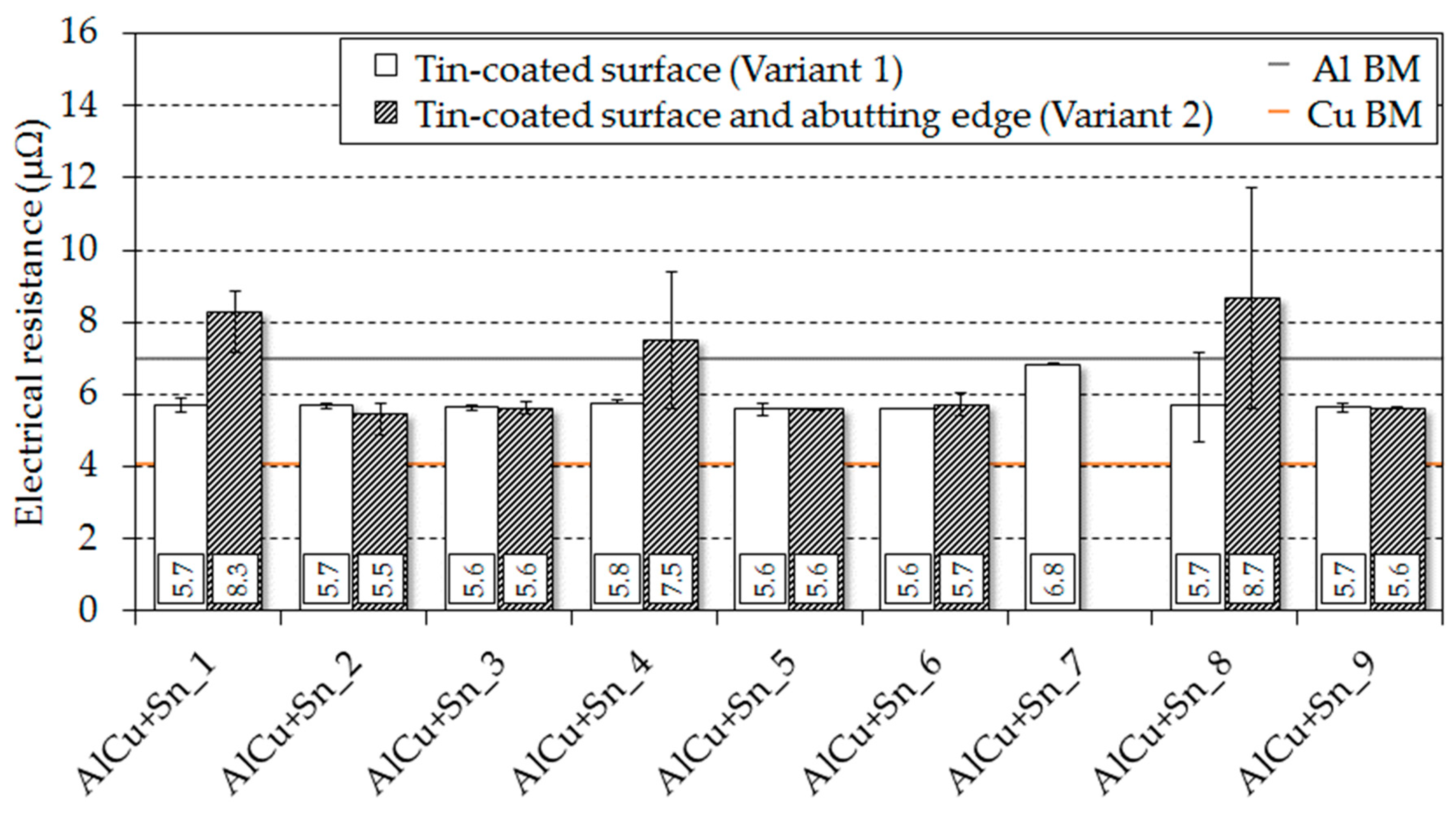
The electrical resistances resulting from the parameter combinations listed in Table 3 are shown in Figure 3. As can be seen, the electrical resistances of the friction stir welded seams were subject to less deviations than the tensile strength values. Consequently, the resultant electrical joint quality of friction stir welds manufactured using aluminum and tinned copper blanks is more robust to parameter variations than the mechanical joint properties. With the exception of parameter combination AlCu+Sn_7, the electrical resistances of joints welded according to variant 1 are located in the middle between the resistances of the base materials used and thus excellent current-carrying behavior has been achieved. Hence, the coating has a negligible effect on the electrical resistance of the joint when tin is only on the surface of the copper workpieces. Parameter combination AlCu+Sn_7 includes the lowest n/v-ratio of the entire experimental design and thus leads to the lowest heat input into the joint. This leads to the suggestion that the heat input was not sufficient to plasticize the joining partners accurately. In the following subsection, this presumption will be further discussed based on metallographic analysis.
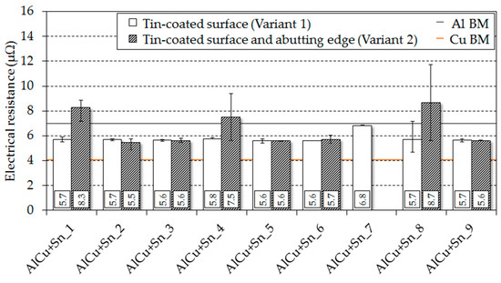
Figure 3.
Results of electrical resistance measurements for the friction stir welds produced using aluminum and tinned copper blanks.
From evaluating the electrical resistances for variant 2 it can be seen that parameter combinations AlCu+Sn_1, AlCu+Sn_4 and AlCu+Sn_8 led to significantly higher values compared to the less conductive aluminum base material. Moreover, it was not possible to determine the electrical resistance for parameter set AlCu+Sn_7 (variant 2) since all three samples welded with this parameter combination were already broken after detaching the specimens by means of water jet cutting. However, with parameter combinations AlCu+Sn_2, AlCu+Sn_3, AlCu+Sn_5, AlCu+Sn_6 and AlCu+Sn_9 it was also demonstrated for this variant that it was possible to realize excellent electrical joint properties with resistances between those of the respective base materials.
When comparing the tensile strength results with the measured electrical resistances of the friction stir welds, it can be said that specimens with high tensile strength values have a better current-carrying behavior.
3.3. Appearance of the AlCu+Sn Friction Stir Welds
In order to explain the previously established differences between individual parameter combinations with regard to the resultant mechanical and electrical joint quality, metallographic analyzes were carried out. As shown in Figure 4, after friction stir welding of aluminum with tinned copper the surface of the weld featured with lots of tin chips. Taking this into account, it was likely that due to the chip formation fine tin particles were stirred into the weld seam during the friction stir welding process.
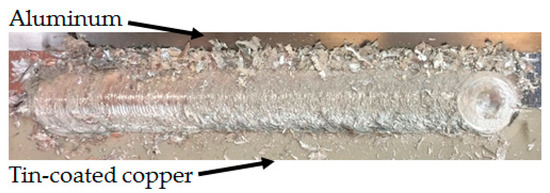
Figure 4.
Documentation of chip formation when welding aluminum with tinned copper.
The tensile strength of tin is 27 MPa [26]. Hence, the mechanical strength of the coating is significantly lower than that of the weaker aluminum base material and it can be assumed that the tin, which is stirred into the aluminum matrix leads to the tensile strength reduction of the joint due to resulting metallurgical notches. If welds are made according to variant 2, due to the tinned abutting edge a higher proportion of tin is to be expected in the joining zone compared to variant 1, so that the reduced tensile strength values of variant 2 could be explained. In this context, it is to be proven that tin from the surface is stirred into the weld seam and that the tin coating applied to the abutting edge causes a higher amount of tin in the stir zone. In order to investigate both hypotheses, the SEM images in Figure 5 were taken by means of BSE from samples that were welded according to parameter combinations AlCu+Sn_4 (variant 1) and AlCu+Sn_3 (variant 2). These samples were of particular interest since they led to the best tensile strength results within this study.

Figure 5.
BSE images for parameter combinations AlCu+Sn_4 (variant 1) and AlCu+Sn_3 (variant 2).
Based on the light gray areas in both BSE images, it can be assumed that for both variants pure tin or tin-rich structures were present in the stir zone. For AlCu+Sn_4 (variant 1) these can only be seen on the left side of the red box, whereas for AlCu+Sn_3 (variant 2) the light gray lamellar features were distributed along the whole stir zone. In order to ensure that the light grey areas were actually tin-containing structures, an EDX element mapping was performed for both samples. By means of an EDX element mapping, a statement could be made about which elements were present in the considered area. The examined sections are marked with red colour in Figure 5.
As shown in Figure 6, the elements aluminum and copper were present in sufficient quantities in both samples so that copper particles stirred into the aluminum matrix could be clearly identified. On the other hand, the detection of tin-rich structures was difficult. One reason for this is that the selected acceleration voltage of 20 kV was not sufficient to knock a bound electron out of the K-shell. In order to achieve this effect with a tin atom, an acceleration voltage of approximately 50 kV is required, which could not be realized with the SEM used. Therefore, only electrons were knocked out of the L-shell of the tin atoms, so that Lα-radiation was detected. Since Lα-radiation is significantly less energetic than Kα-radiation, the detection of tin in the stir zone was particularly challenging. The second reason for the detection of tin being difficult was the finely dispersed distribution of the tin in the stir zone. The local amount of tin is that low that it gets lost in the background noise of the measurement. Therefore, the exact mass ratios cannot be determined. However, as demonstrated in Figure 6, tin was detected in the stir zone for both variants by means of Lα-radiation, so that the previous suggestion that the light grey areas in Figure 5 represent tin-rich structures could be confirmed. Furthermore, it can be concluded that for variant 2 more tin is present in the stir zone than for variant 1, since for variant 2 additionally to the surface of the copper sheet the abutting edge was coated with tin, too. Thus, the differences in tensile strength can be explained with the amount of tin in the joint.
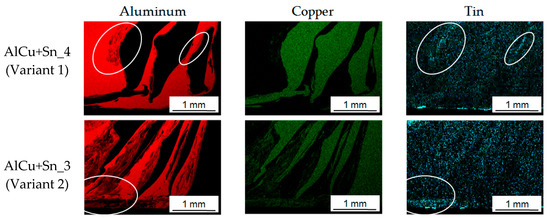
Figure 6.
EDX element mapping: Upper row AlCu+Sn_4 (variant 1) and lower row AlCu+Sn_3 (variant 2).
In the two previous subsections it was observed that parameter sets AlCu+Sn_7 (variant 1) as well as AlCu+Sn_1, AlCu+Sn_4, AlCu+Sn_7 and AlCu+Sn_8 (variant 2) achieved poor mechanical and electrical joint properties compared to the other parameter sets. As shown in Figure 7 for parameter combination AlCu+Sn_7 (variant 1), which includes the lowest n/v-ratio in the considered experimental design, massive defects like cavities and an open seam root are formed in the weld. Thus, it is evident that by using this parameter set the heat input was insufficient in order to plasticize the workpieces accurately and the welding speed was too high so that the material did not have enough time to be transported downwards. For parameter combinations AlCu+Sn_1, AlCu+Sn_7 and AlCu+Sn_8 it was not possible to perform metallographic analysis since the samples broke during water jet cutting. Taking into account the macrostructure of the specimen that was welded according to parameter set AlCu+Sn_4 (variant 2), it could be seen that bonding was only achieved for a small area at the top of the weld. The parameter combinations AlCu+Sn_1, AlCu+Sn_4, AlCu+Sn_7 and AlCu+Sn_8 (variant 2) all included either the lowest tool rotation speed in the experimental design or the highest traverse speed coupled with a low tool rotation speed. Hence, it could be assumed that the tin layer on the abutting edge acted like a lubricating film, which hindered the formation of a firmly bonded joint if the heat input was too low.

Figure 7.
Cross-sectional macrostructures for parameter combinations AlCu+Sn_7 (variant 1) and AlCu+Sn_4 (variant 2).
3.4. Analysis of the Process Data
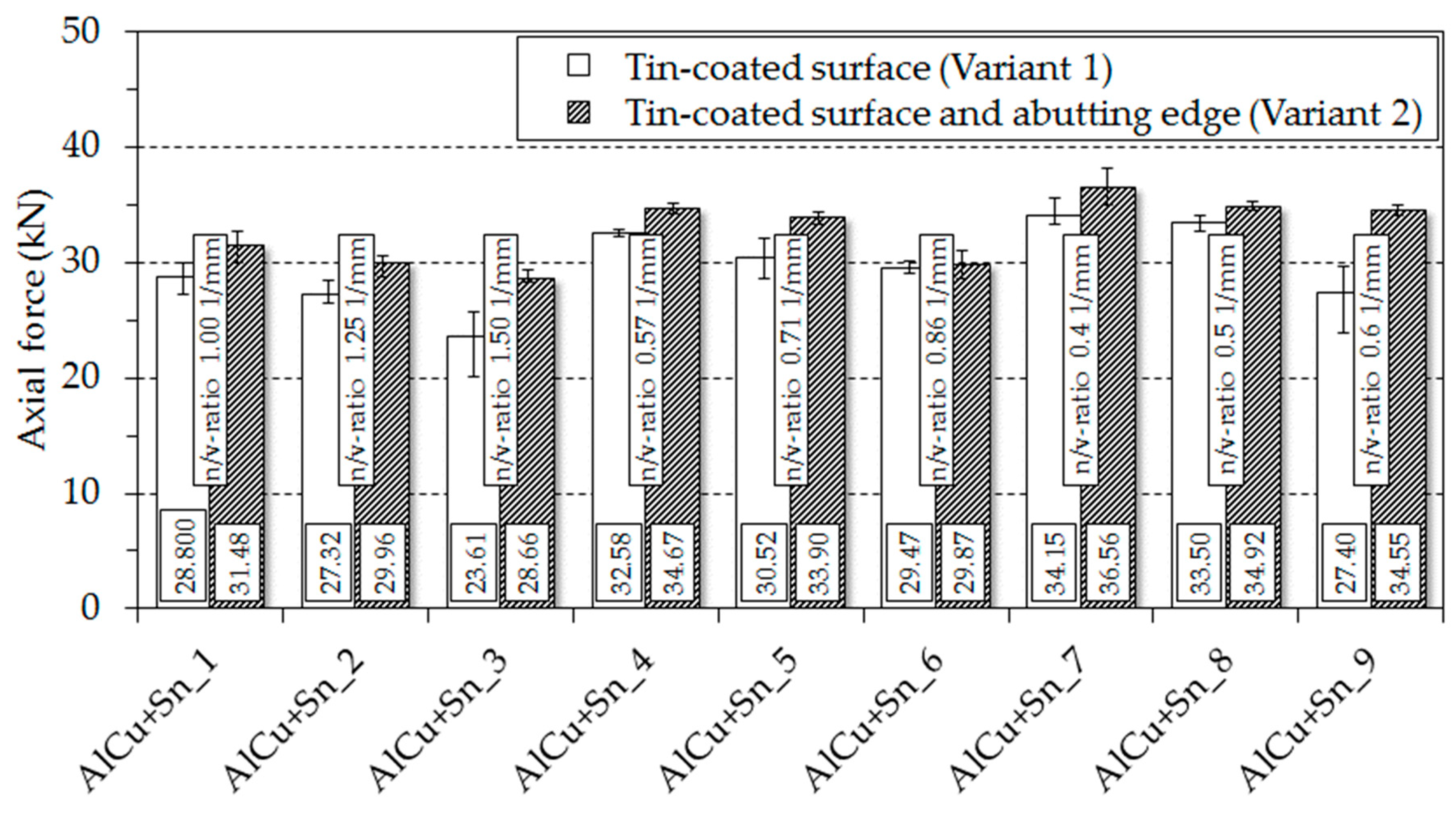
While performing each weld in a position-controlled operation, the respective axial forces were recorded and subsequently averaged over the welding time. The axial force can be used as an indicator for the degree of heat input. The higher the heat input, the higher the plasticization and thus the lower the resistance of the material counteracting the tool rotation axis. Figure 8 shows the axial forces for each parameter combination of the two considered variants.
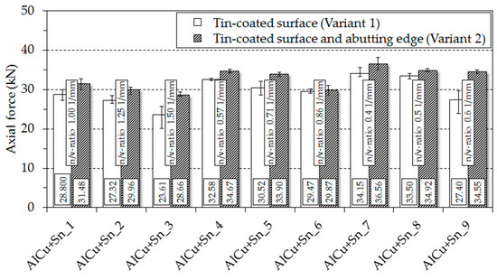
Figure 8.
Average axial forces for the friction stir welding experiments performed using aluminum and tinned copper blanks.
The diagram shows the correlation between heat input and axial force described above. Consequently, the axial forces decreased with an increasing n/v-ratio. Furthermore, it was evident that the axial forces were higher for friction stir welds that were produced according to variant 2. Hence, the process temperatures were higher when the tin coating was applied only to the surface of the copper and not to the abutting edge. This observation supports the suggestion that the tin coating reduces the frictional resistance between the FSW tool and the joining partners so that the workpieces are subject to lower heat input. As a result, the n/v-ratios of the two most efficient parameter sets (AlCu+Sn_4 for variant 1 and AlCu+Sn_3 for variant 2) differed by the factor 2.63. Therefore, it is to be stated that there is a different tribological system when friction stir welds are manufactured using tin coated workpieces and thus the welding parameters require an adjustment so that more heat is generated during the friction stir welding process in order to obtain best possible joint properties.
4. Conclusions
In this study, the influence of copper-sided coating on the weldability and joint formation was investigated for friction stir butt welding of dissimilar aluminum and copper blanks having a thickness of 3 mm. Two different variants were considered. In the first variant, the abutting edge of the copper workpiece was equal to the cutting edge, so that the tin was only on the surface. Within the second variant, the surface of the copper workpiece and also the abutting edge were coated with tin. By varying the process parameters, traverse speed and tool rotation speed, the effect of the parameter selection on the resulting mechanical and electrical joint properties was determined.
- Within the investigations carried out, aluminum and tin coated copper blanks were successfully friction stir butt welded.
- The most efficient parameter combinations led to a tensile strength of 83.7% for variant 1 and 76.3% for variant 2 compared to the tensile strength of the weaker aluminum base material. Furthermore, these parameter sets achieved excellent electrical joint properties with electrical resistances that were between those of the base materials used. Therefore, it was noted that the copper-sided tinning had a negligible effect on the electrical properties of the friction stir welds.
- By means of SEM, it was shown that the amount of tin in the stir zone increased when, in addition to the surface of the copper blanks, the abutting edge was also coated.
- A correlation between the amount of tin stirred into the joint and the resulting mechanical joint properties was observed. The tensile strength of the friction stir welds decreased with an increasing amount of tin.
- By analyzing the axial forces that were recorded during the welding experiments in a position-controlled operation, it could be proven that the tin coating alters the tribological system and that higher heat input is required when, in addition to the surface of the copper blanks, the abutting edge is tinned, too.
According to the investigations carried out, it could be shown that joints with good performance can be produced when tin coated copper blanks are friction stir butt welded to aluminum. The friction stir welds achieve excellent electrical properties and the tensile strength is only slightly reduced compared to the weaker aluminum base material. Thus, it can be concluded that if these tensile strength losses can be accepted, friction stir welding of aluminum to tin coated copper is applicable.
Author Contributions
Conceptualization, N.E., Y.H and A.H.; methodology, N.E. and Y.H.; formal analysis, N.E., A.H. and D.L.; investigation, N.E. and Y.H.; writing-original draft preparation, N.E. and D.L.; writing-review & editing, A.H. and S.B..; visualization, N.E. and Y.H.; supervision, A.H. and S.B.; project administration, A.H.
Conflicts of Interest
The authors declare no conflict of interest.
References
- Li, X.-W.; Zhang, D.-T.; Qiu, C.; Zhang, W. Microstructure and mechanical properties of dissimilar pure copper/1350 aluminum alloy butt joints by friction stir welding. Trans. Nonferrous Metals Soc. China 2012, 22, 1298–1306. [Google Scholar] [CrossRef]
- Bargel, H.-J.; Schulze, G. Werkstoffkunde; Springer: Berlin, Germany, 2016. [Google Scholar]
- Deutsches Kupfer-Institut e.V. Kupfer in der Elektrotechnik—Kabel und Leitungen; Deutsches Kupfer-Institut e.V.: Düsseldorf, Germany, 2000. [Google Scholar]
- Carlone, P.; Astarita, A.; Palazzo, G.S.; Paradiso, V.; Squillace, A. Microstructural aspects in Al–Cu dissimilar joining by FSW. Int. J. Adv. Manuf. Technol. 2015, 79, 1109–1116. [Google Scholar] [CrossRef]
- Braunovic, M.; Myshkin, N.K.; Konchits, V.V. Electrical Contacts. Fundamentals, Applications and Technology; Taylor & Francis Distributor: Boca Raton, FL, USA, 2007. [Google Scholar]
- Khodir, S.A.; Ahmed, M.M.Z.; Ahmed, E.; Mohamed, S.M.R.; Abdel-Aleem, H. Effect of Intermetallic Compound Phases on the Mechanical Properties of the Dissimilar Al/Cu Friction Stir Welded Joints. J. Mater. Eng. Perform. 2016, 25, 4637–4648. [Google Scholar] [CrossRef]
- Celik, S.; Cakir, R. Effect of Friction Stir Welding Parameters on the Mechanical and Microstructure Properties of the Al-Cu Butt Joint. Metals 2016, 6, 133. [Google Scholar] [CrossRef]
- Muthu, M.F.X.; Jayabalan, V. Tool travel speed effects on the microstructure of friction stir welded aluminum–copper joints. J. Mater. Process. Technol. 2015, 217, 105–113. [Google Scholar] [CrossRef]
- Saeid, T.; Abdollah-zadeh, A.; Sazgari, B. Weldability and mechanical properties of dissimilar aluminum–copper lap joints made by friction stir welding. J. Alloys Compd. 2010, 490, 652–655. [Google Scholar] [CrossRef]
- Xue, P.; Xiao, B.L.; Ni, D.R.; Ma, Z.Y. Enhanced mechanical properties of friction stir welded dissimilar Al–Cu joint by intermetallic compounds. Mater. Sci. Eng. A 2010, 527, 5723–5727. [Google Scholar] [CrossRef]
- Barekatain, H.; Kazeminezhad, M.; Kokabi, A.H. Microstructure and Mechanical Properties in Dissimilar Butt Friction Stir Welding of Severely Plastic Deformed Aluminum AA 1050 and Commercially Pure Copper Sheets. J. Mater. Sci. Technol. 2014, 30, 826–834. [Google Scholar] [CrossRef]
- Zhang, Q.-Z.; Gong, W.-B.; Liu, W. Microstructure and mechanical properties of dissimilar Al–Cu joints by friction stir welding. Trans. Nonferrous Metals Soc. China 2015, 25, 1779–1786. [Google Scholar] [CrossRef]
- Thomas, W.M.; Nicholas, E.D.; Needham, J.C.; Murch, M.G.; Templesmith, P.; Dawes, C.J. Improvements Relating to Friction Welding. WO 93/10935, 10 June 1993. [Google Scholar]
- Eslami, N.; Harms, A.; Deringer, J.; Fricke, A.; Böhm, S. Dissimilar Friction Stir Butt Welding of Aluminum and Copper with Cross-Section Adjustment for Current-Carrying Components. Metals 2018, 8, 661. [Google Scholar] [CrossRef]
- Vilaça, P.; Thomas, W. Friction Stir Welding Technology. In Structural Connections for Lightweight Metallic Structures; Moreira, P.M.G.P., da Silva, L.F.M., de Castro, P.M.S.T., Eds.; Springer: Berlin/Heidelberg, Germany, 2012; pp. 85–124. [Google Scholar]
- Mishra, R.S.; Ma, Z.Y. Friction stir welding and processing. Mater. Sci. Eng. R Rep. 2005, 50, 1–78. [Google Scholar] [CrossRef]
- Xue, P.; Ni, D.R.; Wang, D.; Xiao, B.L.; Ma, Z.Y. Effect of friction stir welding parameters on the microstructure and mechanical properties of the dissimilar Al–Cu joints. Mater. Sci. Eng. A 2011, 528, 4683–4689. [Google Scholar] [CrossRef]
- Akinlabi, E.T. Characterisation of Dissimilar Friction Stir Welds between 5754 Aluminium Alloy and C11000 Copper. D-Tech Thesis, Nelson Mandela Metropolitan University, Port Elizabeth, South Africa, 2010. [Google Scholar]
- Deutsches Institut für Normung e.V. Aluminium und Aluminiumlegierungen—Chemische Zusammensetzung und Form von Halbzeug—Teil 3: Chemische Zusammensetzung und Erzeugnisformen; DIN EN 573-3; Beuth Verlag GmbH: Berlin, Germany, 2013. [Google Scholar]
- Deutsches Institut für Normung e.V. Kupfer und Kupferlegierungen—Platten, Bleche und Bänder aus Kupfer für die Anwendung in der Elektrotechnik; DIN EN 13599; Beuth Verlag GmbH: Berlin, Germany, 2014. [Google Scholar]
- Eslami, N.; Hischer, Y.; Harms, A.; Lauterbach, D.; Böhm, S. Optimization of Process Parameters for Friction Stir Welding of Aluminum and Copper Using the Taguchi Method. Metals 2019, 9, 63. [Google Scholar] [CrossRef]
- Weißbach, W.; Dahms, M. Werkstoffkunde. Strukturen, Eigenschaften, Prüfung; 18., überarbeitete Auflage; Vieweg + Teubner: Wiesbaden, Germany, 2012. [Google Scholar]
- Kleih, L.G. Theoretische und experimentelle Analyse des Bauteilverhaltens rührreibgeschweißter Überlappverbindungen; Universitätsbibliothek der Universität Stuttgart: Stuttgart, Germany, 2014. [Google Scholar]
- Deutsches Institut für Normung e.V. Rührreibschweißen—Aluminium-Teil 5: Qualitäts-und Prüfungsanforderungen; DIN EN ISO 25239-5; Beuth Verlag GmbH: Berlin, Germany, 2012. [Google Scholar]
- Deutsches Institut für Normung e.V. Zerstörende Prüfung von Schweißverbindungen an metallischen Werkstoffen—Querzugversuch; DIN EN ISO 4136:2012; Beuth Verlag GmbH: Berlin, Germany, 2013. [Google Scholar]
- Material Archiv. Zinn. Available online: http://www.materialarchiv.ch/app-tablet/#detail/896/zinn (accessed on 12 December 2018).
© 2019 by the authors. Licensee MDPI, Basel, Switzerland. This article is an open access article distributed under the terms and conditions of the Creative Commons Attribution (CC BY) license (http://creativecommons.org/licenses/by/4.0/).