Abstract
Although short-pitch resistance spot welding (RSW) significantly increases vehicle body strength, its application has been limited because of the associated shunting effect. In this study, a reference-based adaptive RSW process intended to minimize the shunting effect was proposed, and a related RSW system that controls welding current and power was developed to implement the adaptive method. The proposed RSW method compensates for the heat input loss caused by the shunting effect based on the estimated weld pitch and reference data obtained under suitable welding conditions. An exponential model was developed using a unique indicator (i.e., the ratio of the adaptive welding heat input to the reference welding heat input until the reference welding power curve peak) to estimate the weld pitch. A logistic growth model was next developed based on the relationship of the nugget diameter, heat input, and weld pitch to estimate the heat input compensation. A unique strategy using power control with a modified reference power curve was applied to supply the calculated heat input compensation. The experimental results intended to validate the proposed adaptive RSW process indicated that the proposed process effectively reduced the shunting effect and produced an improved nugget shape relative to the conventional RSW process.
1. Introduction
In response to enforceable vehicle fuel efficiency regulations, such as the Corporate Average Fuel Efficiency (CAFE) Standards intended to improve the fuel economy of light trucks and cars [1], automotive equipment manufacturers have developed and applied various lightweight technologies using high-strength steel (HSS) in their vehicle bodies [2,3,4]. In addition to meeting fuel efficiency standards, these lightweight vehicle body parts must also meet various vehicle crashworthiness standards, such as the Small Overlap Frontal Crashworthiness Evaluation. This safety standard was introduced by the Insurance Institute for Highway Safety (IIHS) in 2012 and addresses one of the most serious crash scenarios [5,6]. The design and stiffness of the joints between vehicle body parts, as well as the material properties that make up the parts, are important for ensuring vehicle crashworthiness.
Resistance spot welding (RSW) is the leading joining technology used in vehicle bodies. In general, the resistance spot weldability of HSS sheets is poorer than that of conventional steel sheets because of narrow suitable welding range [7] and the low toughness of the welds caused by the high content of alloying elements [8]. Although the use of HSS increases the strength of structures used in a car body, the strength of the spot welds is often compromised. The cross tension strength (CTS) and absorbed energy of the spot welds actually decrease as the base metal strength increases. The tensile shear strength (TSS) and fatigue strength of the spot welds show little and no increase, respectively, as the base metal strength increases [9]. Efforts to improve the mechanical performance of vehicle body parts made of HSS and joined by RSW have focused on either improving (1) the weld’s material and mechanical properties or (2) the welded joint design. Considering the weld’s material and mechanical properties, welding methods using power control rather than conventional constant current control (CCC) to increase nugget size and improve the weldability of HSS sheets for automotive applications have been investigated [10,11]. Alternatively, postweld heat treatments have been studied to improve a weld’s microstructure and material properties using pulsed welding current profiles in HSS [12,13] and improve a weld’s mechanical properties in situ in transformation-induced plasticity (TRIP) steel [14]. Considering the welded joint design, RSW with a weld pitch of ≤40 mm (short-pitch RSW) has been found to significantly increase the vehicle body strength [15]. Short-pitch RSW can increase the strength of welded structures by increasing the number of weld spots [16]. However, when the pitch between welds is reduced, the quality of the subsequent weld is adversely affected because of the shunting effect [17].
A method for reducing the shunting effect is required to fully realize the benefits of short-pitch RSW, which in turn requires a thorough understanding of the shunting effect phenomenon. Based on prior research, dominant factors affecting shunting include weld pitch and surface condition, and process parameters, such as electrode force, welding time, and current, also affect shunting [18]. An analytical model based on the equivalent joule heat generated during welding was developed to further investigate the effects of various process parameters on shunting [19]. These and similar findings have led to the development of various welding methods intended to reduce the shunting effect in short-pitch RSW by compensating for the heat input loss caused by the shunting effect [20] or adapting welding processes to stabilize weld quality in a production line [15]. Smart welding systems have subsequently been developed and applied in production lines to address abnormal conditions resulting from the shunting effect, poor fit-up, etc. Most recently, a reference-based adaptive RSW method was proposed that compensates for the heat input loss caused by the shunting effect by increasing the welding time under CCC until the amount of heat input that would reduce the shunting effect is obtained [21]. Although several previous studies have investigated the shunting effect phenomenon in RSW, fewer studies have considered the development of an adaptive RSW method and related system that directly reduces the shunting effect.
In this study, a reference-based adaptive RSW method intended to reduce the shunting effect and a related RSW system using combined power and current controls that implements this adaptive method were developed. First, an exponential regression model capable of estimating weld pitch as a function of welding signal was developed. Next, a logistic growth model capable of estimating heat input compensation based on the relationship between nugget diameter, heat input, and weld pitch was developed. A user-controlled coefficient was added to more effectively adjust the heat input compensation. To compensate for the heat input loss caused by the shunting effect, the proposed RSW method and system control the welding power based on the reference welding power waveform without adjusting welding time. Finally, the proposed adaptive RSW process was experimentally validated by comparing the test results with the conventional RSW process.
2. Literature Review
A review of other RSW methods and systems previously reported in the literature was conducted to support the development of the reference-based adaptive RSW method and system proposed in this study. In advanced RSW processes, a medium-frequency direct-current (MFDC) welding system is generally used. This type of system, with a working frequency of approximately 1000 Hz, not only provides fast and precise control of welding current and voltage in various forms, but also offers a wider suitable welding range and better welding quality than alternating current (AC) welding systems [22]. Various related welding methods have been developed using MFDC welding systems. Among these methods, CCC is most commonly applied using fuzzy [23] or closed-loop [24] control algorithms. Despite its broad use, CCC is limited in its ability to improve the weldability of difficult-to-weld metals, including HSS. In response, welding methods based on constant power control, which can adjust the heat input by directly controlling the welding power, were developed [10]. Welding methods using constant power control reduce expulsion caused by excessive heat input at the early stage of the welding process. Similarly, Yu [11] proposed two RSW methods, namely the reference and modified reference welding methods, intended to improve the weldability of HSS using a power control strategy based on predefined reference power curves.
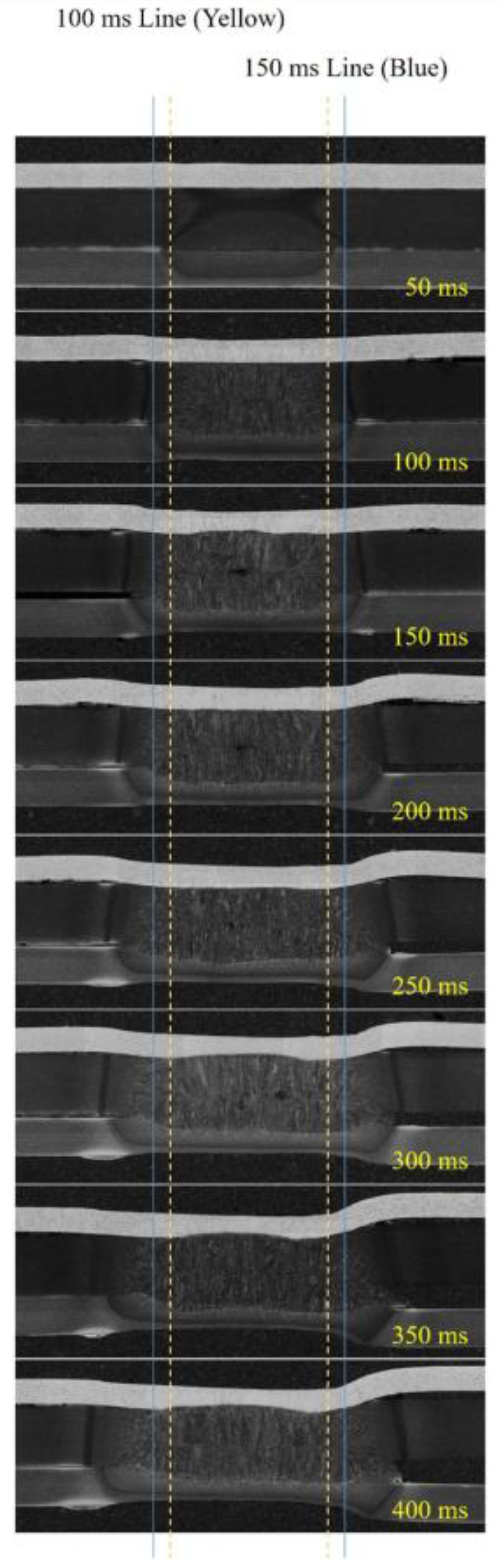
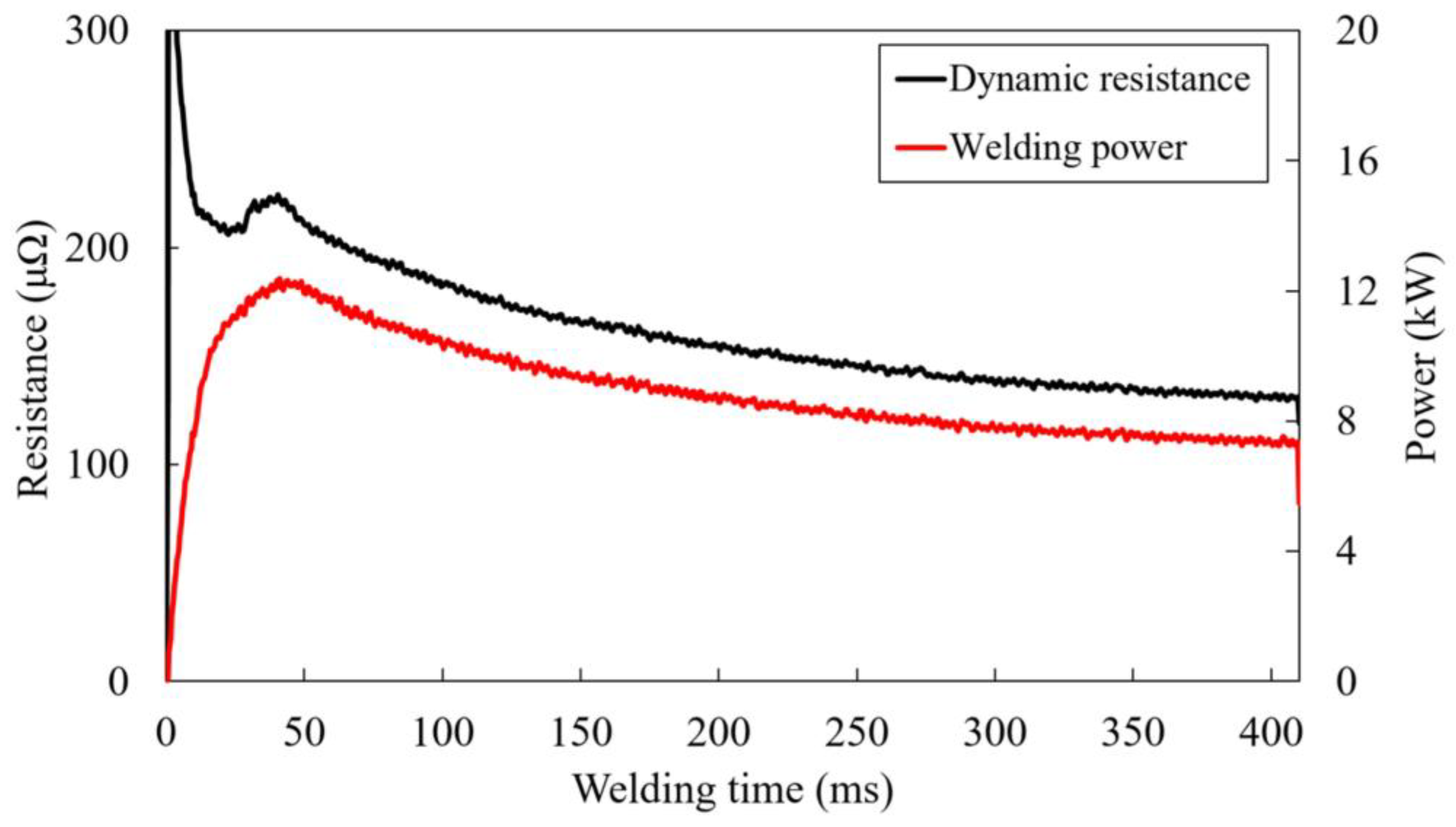
None of the RSW methods previously described include adaptive capabilities or algorithms that can ensure improved weldability throughout a dynamic welding process. Yu et al. [21] most recently developed a reference-based adaptive RSW method to reduce the shunting effect in short-pitch RSW. This method estimates the weld pitch based on the dynamic resistance signal and subsequently compensates for the heat input loss caused by the shunting effect by increasing the welding time under CCC until the target heat input is obtained. Although this adaptive RSW method significantly reduced the shunting effect, it did not sufficiently increase the nugget diameter. The nugget diameter of the weld affected by shunting was less than the nugget diameter of the weld unaffected by shunting. In addition, the strategy of changing the welding time can make it difficult to apply this method to production lines. Figure 1 and Figure 2, which show nugget growth, dynamic resistance, and welding power as a function of welding time, better illustrate the limitations of the adaptive RSW method proposed by Yu et al. [21]. In Figure 1, most of the nugget growth occurred within the first 150 ms because of the high heat input caused by the high dynamic resistance. After 150 ms, the nugget grew more slowly. After 250 ms, little to no nugget growth can be observed. In Figure 2, the dynamic resistance and welding power trends were consistent with the nugget growth trend during welding. Based on this phenomenon, the strategy that extends welding time with CCC to increase the heat input clearly has a limitation in growing nugget size. Therefore, an alternate RSW method that can compensate for the heat input loss caused by the shunting effect while increasing the nugget diameter is required.
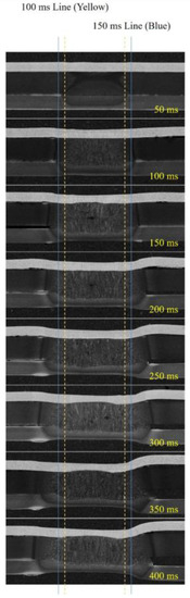
Figure 1.
Nugget growth as a function of welding time.
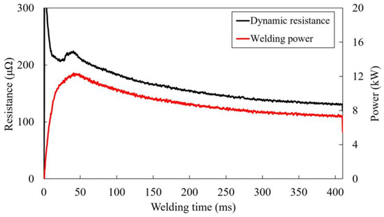
Figure 2.
Dynamic resistance and welding power as a function of welding time.
3. Experimental System and Procedure
3.1. System Development
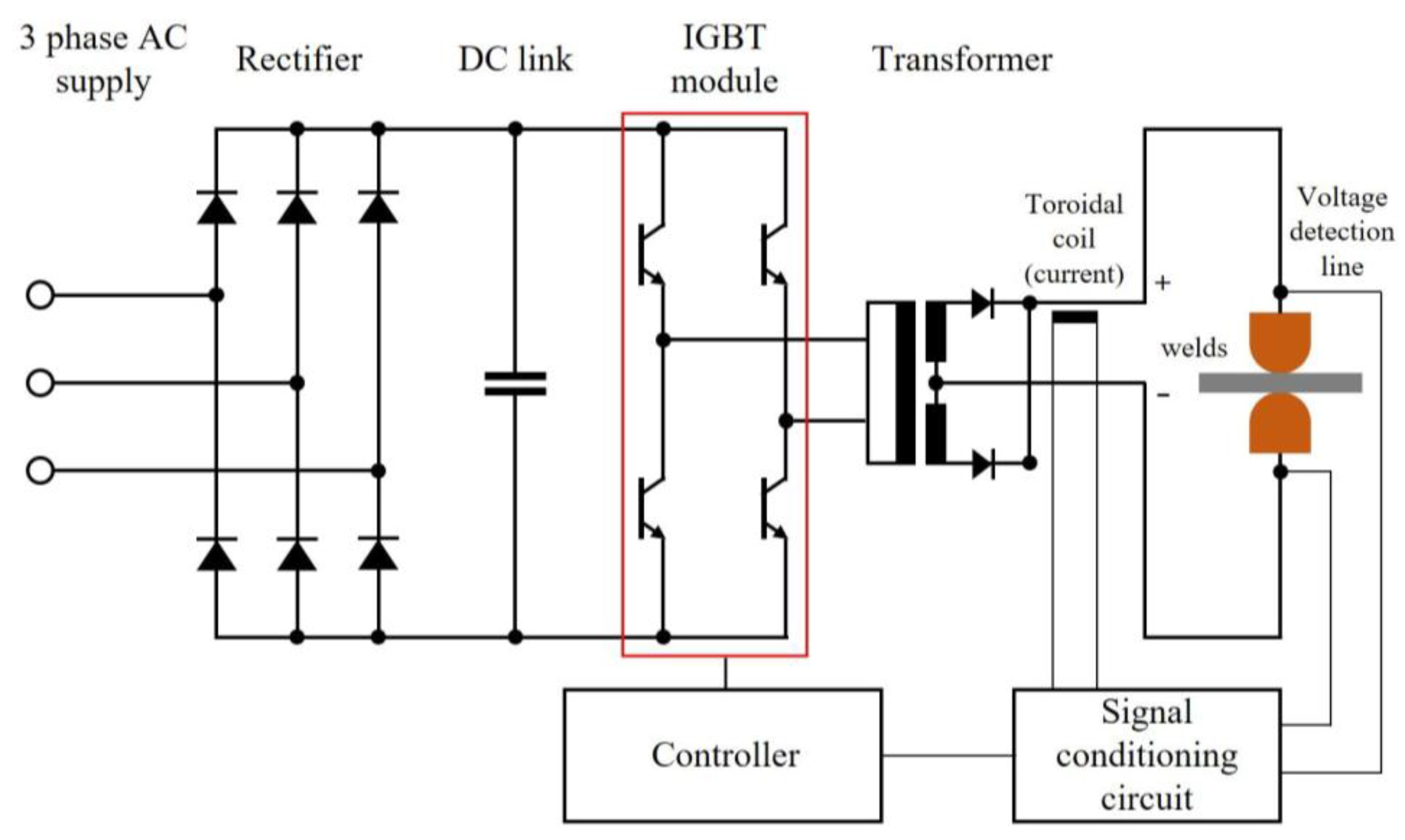
A related RSW system with combined power and current control capabilities was developed to support the implementation of the proposed reference-based adaptive RSW method. Figure 3 shows a schematic of the proposed system. An MFDC system forms the basis of this design. A rectifier converts the three-phase AC supply (380 V and 60 Hz) to DC. A capacitor, DC link, connects the rectifier and the inverter (insulated-gate bipolar transistor (IGBT) module, CM300DY-28H) and performs DC filtering and energy buffering. The DC produced by the rectifier and the DC link was switched by a 1.0 kHz pulse-width modulation (PWM) signal from the controller and inverted to the AC with 1.0 kHz. The high-voltage, low-current AC with 1.0 kHz was converted to low-voltage, high-current AC with 1.0 kHz by a welding transformer. The transformed AC was subsequently converted to DC by diodes in the transformer. The current from the transformer was smoothed by the weld gun impedance.

Figure 3.
Proposed reference-based adaptive resistance spot welding (RSW) system.
For feedback control, the welding current was measured using a toroidal coil inside the transformer, and the welding voltage was measured using detection lines attached to both ends of the electrode tips. These measured signals were transmitted back to the controller’s analog-to-digital converter (ADC) via the signal conditioning circuits. While continuously monitoring the welding process, the controller processed the feedback signals and adjusted the electrode force controls using an electropneumatic regulator and the controller’s digital-to-analog circuit (DAC).
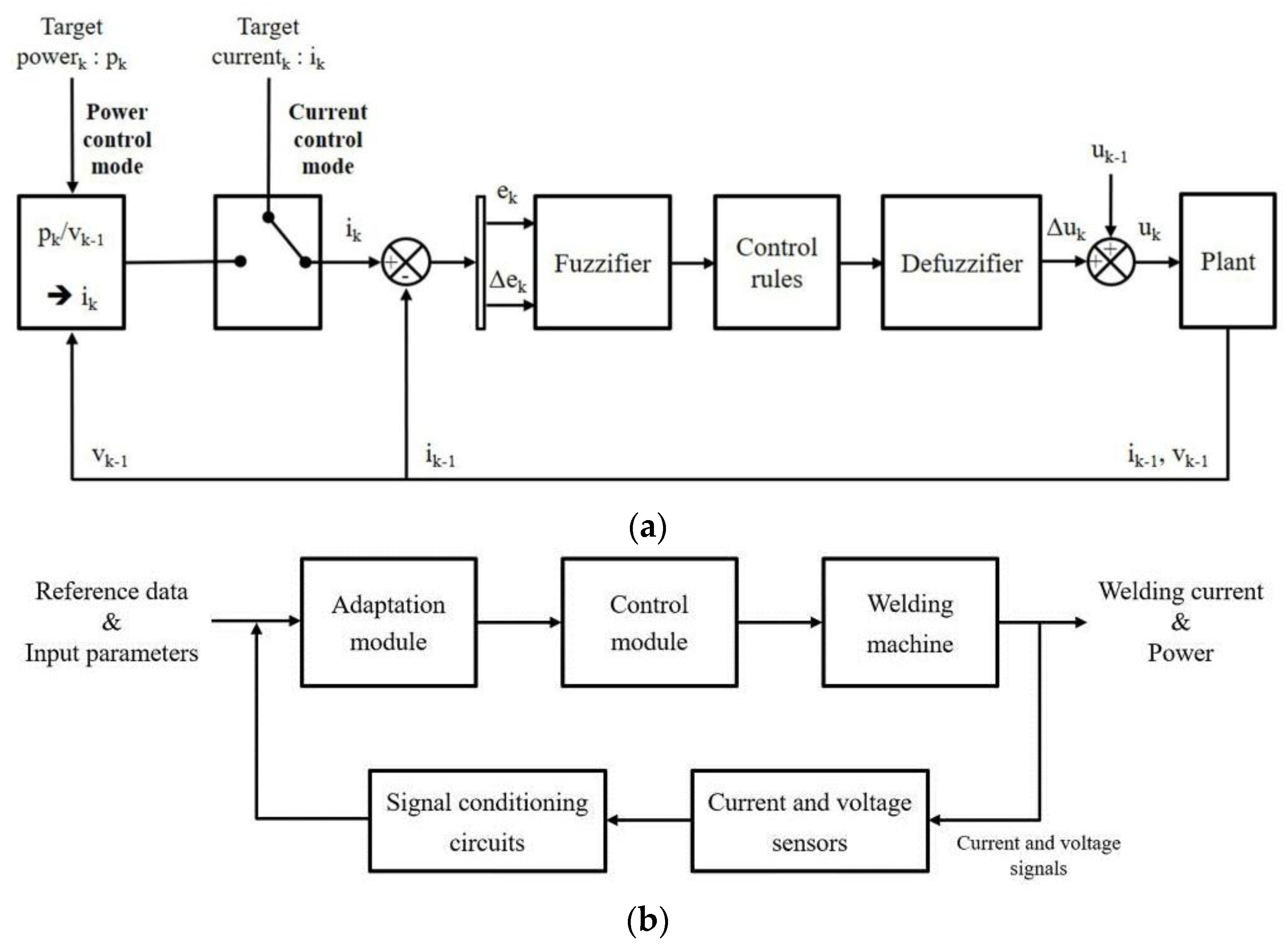
The reference-based adaptive RSW method proposed in this study included both current and power control; hence, the related RSW system tasked with implementing this method must include both power and current control capabilities. Figure 4a shows the block diagram of the controller that support the welding current and power control, and Figure 4b shows system components that support adaptive welding process.
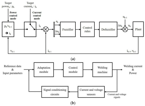
Figure 4.
Proposed RSW system components that support the (a) welding current and power control and (b) adaptive welding process.
The control modes for current and power were located in the control module and applied according to a predefined process control sequence. The welding power was controlled via the welding current using fuzzy-proportional integral (PI) control. The welding power and current used to determine the target welding power were calculated as follows:
where, p(t) is the power; v(t) is the tip voltage; i(t) is the welding current; ik is the target current for the current controller; pk is the target welding power; and vk−1 is the feedback voltage measured in the previous cycle. The calculated current is the target current for the current controller. This relationship formed the basis of the current control in addition to supporting the power control. An adaptation scheme module upstream of the control module supported the estimation of the weld pitch and the compensation of the heat input loss caused by the shunting effect. The internal processes of the adaptation scheme module were detailed in Section 4.
3.2. Experimental Procedure
Experiments were performed in parallel with the welding system development to collect the data for developing the algorithms included in the adaptation scheme module. The proposed adaptive RSW method and system were also experimentally validated by comparing the test results with the conventional RSW method. Specifically, four short-pitch spot welds were sequentially produced using a conventional CCC and the proposed adaptive RSW methods.
Test specimens measuring 30 × 100 mm were prepared using three types of steel sheets commonly applied to vehicle body reinforcement members: low-carbon (SGACEN), dual-phase (DP980), and complex-phase (CP1180). Table 1 presents details on the thickness, tensile strength, coating, and chemical composition for each of the test materials. The steel sheets were stacked with the SGACEN as the positive electrode side, the DP980 sheet as the negative electrode side, and the CP1180 in the middle. This stacking order mimicked the three-sheet lap welding combination used in crash members (comprising a low-carbon steel outer panel, an HSS reinforcement member, and an HSS inner structure). Chromium-copper (Cu-Cr) dome-type cap tips with a 40 mm tip radius and a 6 mm tip diameter were used. The tips were used to make 50 welds prior to experimentation to ensure their stabilization.

Table 1.
Steel sheet material specifications.
An initial experiment using RSW under CCC was conducted with various weld pitches and currents to investigate the shunting effect in RSW and the relationship between the weld pitch and the measured data (e.g., power signal and heat input). Table 2 details the welding conditions, including the weld pitch, welding current, welding time, electrode force, hold time, and cooling water characteristics.
Table 2.
Experimental welding conditions.
The minimum welding current defined as the current immediately before the occurrence of expulsion was determined through repeated single spot-weld tests at 0.5 kA current intervals. Current and voltage were sampled every 0.5 ms using the sensors in the proposed adaptive RSW system. Their averaged values were subsequently used to calculate the welding power, dynamic resistance, and heat input using Equations (1), (3) and (4), respectively.
where r(t) is the resistance at 0.5 ms intervals, and Q is the total heat input during the total welding time.
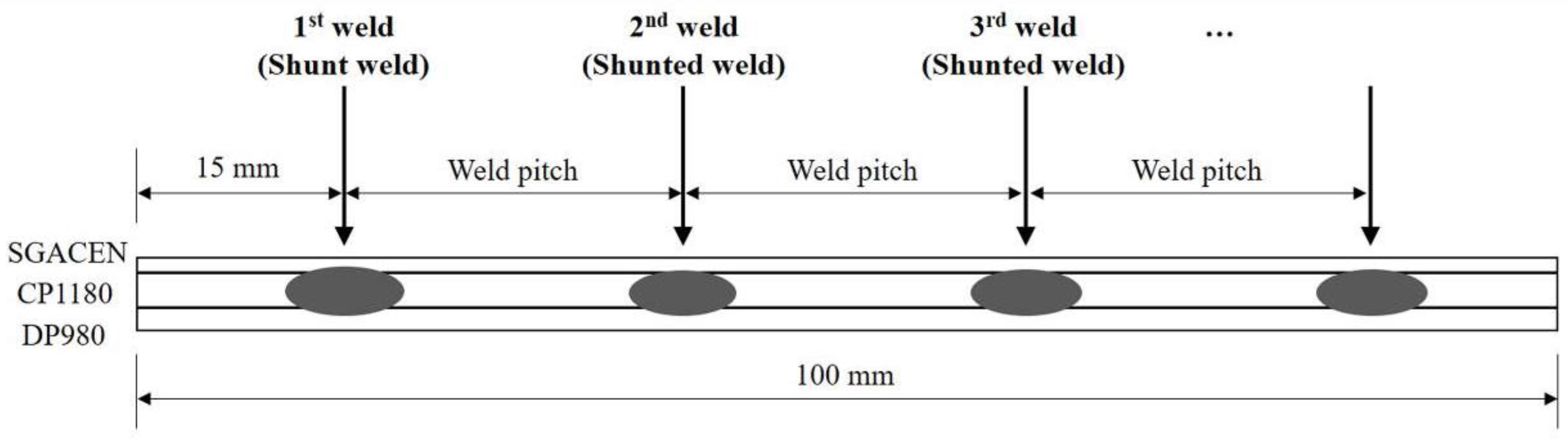
Figure 5 shows the RSW sequence applied to the test specimens under variable weld pitch and current conditions. The center-to-center distance of each weld is the weld pitch. The first test weld (the shunt weld) receives all of the applied current and, therefore, unaffected by shunting. The second test weld (the shunted weld) shares the applied current with the initial shunt weld and, therefore, affected by shunting.
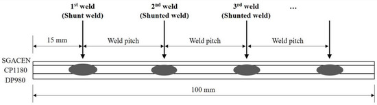
Figure 5.
Resistance spot welding sequence applied to the test specimens. Steel sheets: low-carbon (SGACEN), complex-phase (CP1180), and dual-phase (DP980).
A series of welds were made using various weld pitches and minimum welding current (7.5 kA) indicated in Table 2 to investigate on the shunting effect on the dissimilar, stacked steel sheets used herein. The welding current was next increased in 0.5 kA intervals to determine the amount of heat input compensation for each weld pitch. The shunting effect was assessed by comparing the welding signal curves and the nugget diameters for the shunt and shunted welds. Based on these experimental results, statistical models were developed to estimate the weld pitch and the heat input required to compensate for the shunting effect. These statistical models were subsequently introduced into the adaptation scheme module of the proposed reference-based adaptive RSW system.
4. Proposed Reference-Based Adaptive RSW Method
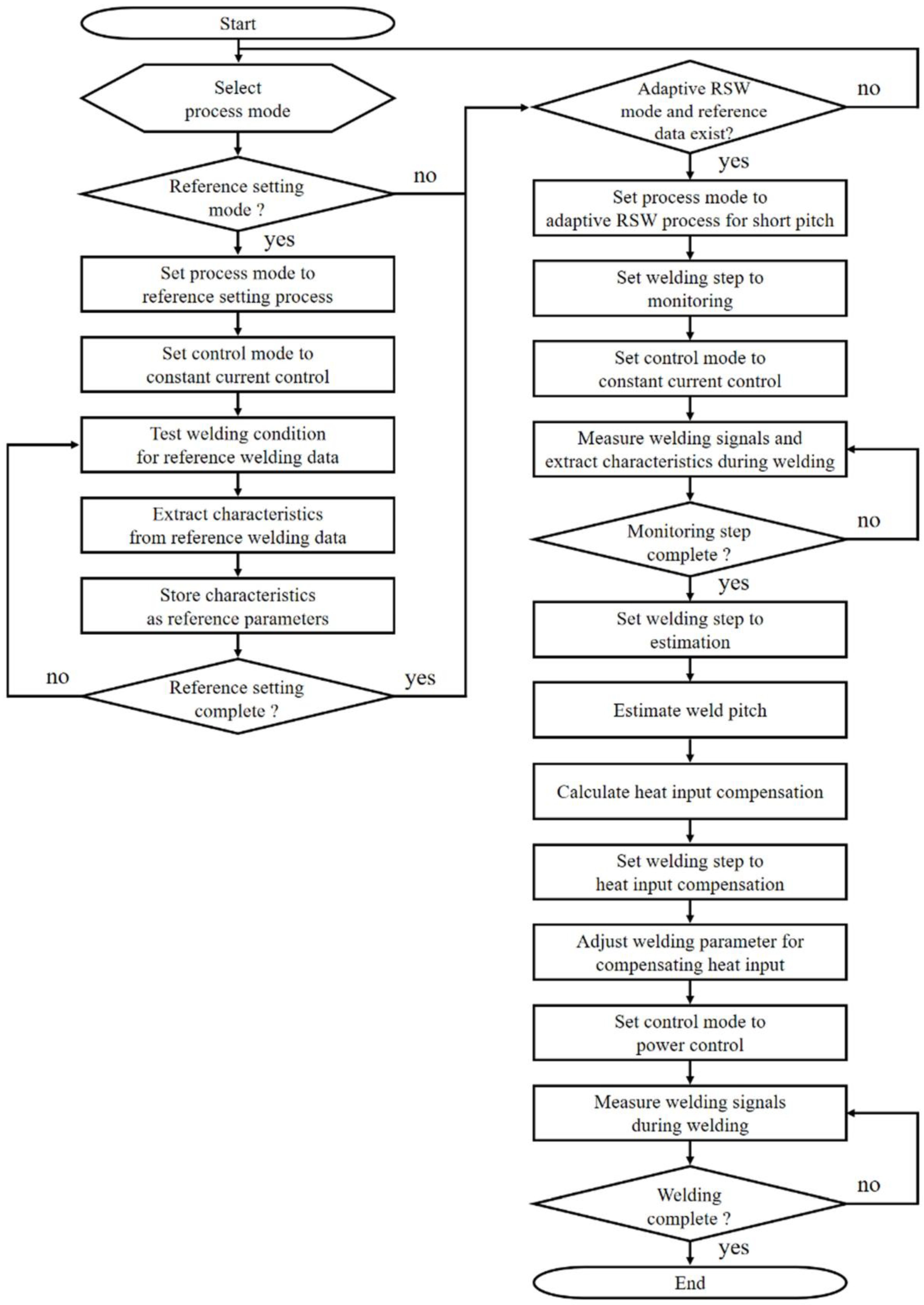
Figure 6 shows the stepwise reference-based adaptive RSW method proposed in this study. The method uses both constant current and power control and includes two operational modes: (1) the reference setting mode, which collects and processes reference welding data under CCC and (2) the adaptive RSW mode, which uses the processed reference welding data to compensate for the heat loss caused by the shunting effect using both CCC and power control.
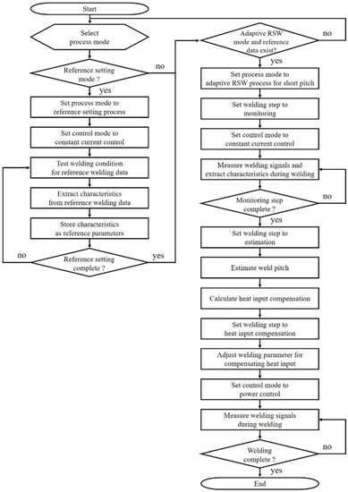
Figure 6.
Proposed reference-based adaptive RSW method.
In the reference-setting mode, the suitable welding condition is initially determined as the reference condition by conducting a few single spot welding without the shunting effect. This condition was generally included within the suitable welding range and close to the upper boundary of the suitable welding range (occurrence of expulsion). Both the welding characteristics and the welding signals from this reference welding condition were calculated and measured, respectively, and stored as reference parameters in the proposed adaptive RSW system’s controller. The subsequent adaptive RSW mode comprised three steps: (1) monitoring, (2) estimation, and (3) heat input compensation. Early in this process, the welding characteristics and the welding signals were measured and calculated, respectively, using CCC to support monitoring. Next, the weld pitch and the required heat input were sequentially estimated, and the welding parameters controlling the heat input compensation were adjusted. Finally, the adjusted welding parameters were used to alter the welding process using power control to reduce the shunting effect. Power control was specifically used to compensate for the heat input loss after the estimation step in the adaptive RSW mode. Integral to the overall adaptive RSW mode processes, a detailed description of the weld pitch estimation, heat input compensation estimation, and heat input compensation supply follows in Section 4.1, Section 4.2 and Section 4.3.
4.1. Weld Pitch Estimation
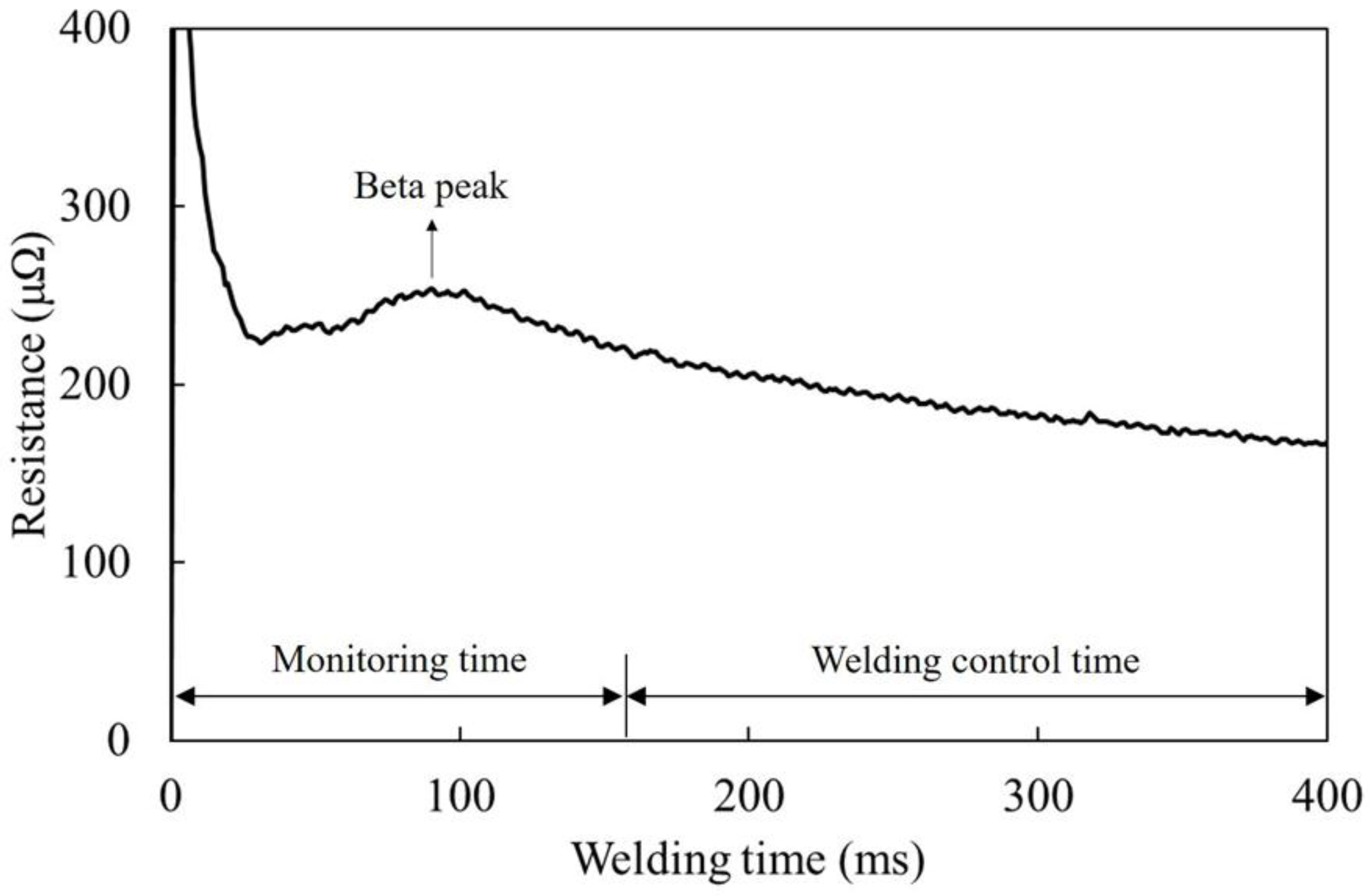
In previous studies, dynamic resistance waveforms were typically used to monitor the welding processes and predict the weld quality [25,26]. However, this method was not efficient for adaptive welding processes that monitor and control welding process in real time within a given time because of the lengthy time requirement of extracting features from the dynamic resistance waveform. The time required to locate and use the dynamic resistance β-peak, which is a significant feature of interest, is lengthy because additional time is needed to confirm the β-peak after it is initially located. Furthermore, if the dynamic resistance β-peak is delayed, more time is needed to locate and confirm its existence, and less time is available to apply strategies for improving the weld quality. Figure 7 shows this relationship. In the short-pitch RSW, an increase in the shunting effect delays the dynamic resistance β-peak and decreases the waveform valley. In this case, even though more heat input compensation is needed, the welding time for the compensation is shortened. Therefore, a unique indicator for estimating the shunting effect (weld pitch) was used to overcome the limitation of using dynamic resistance waveform.
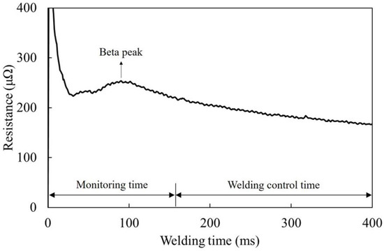
Figure 7.
Relationship between the β-peak and the monitoring and welding control times.
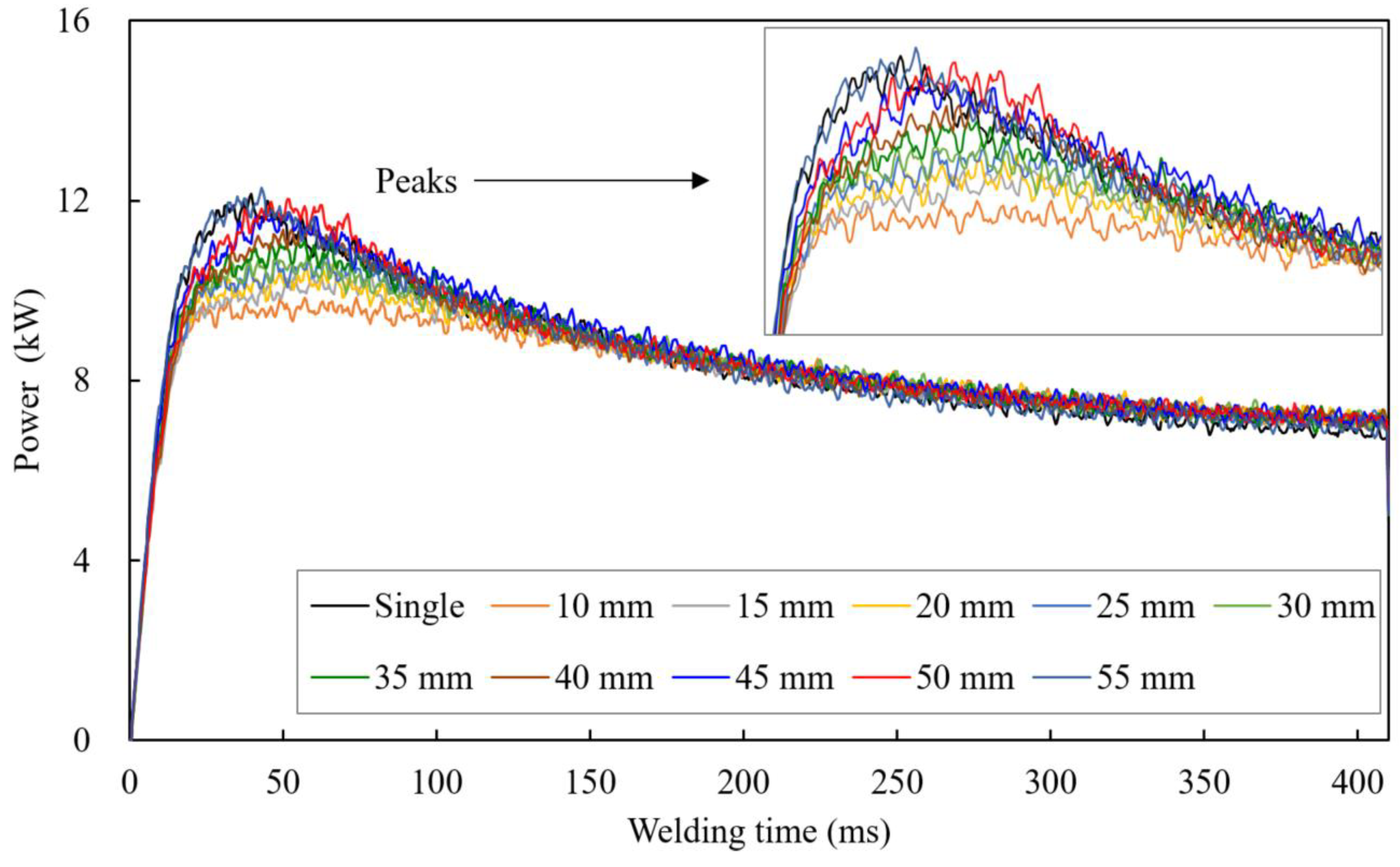
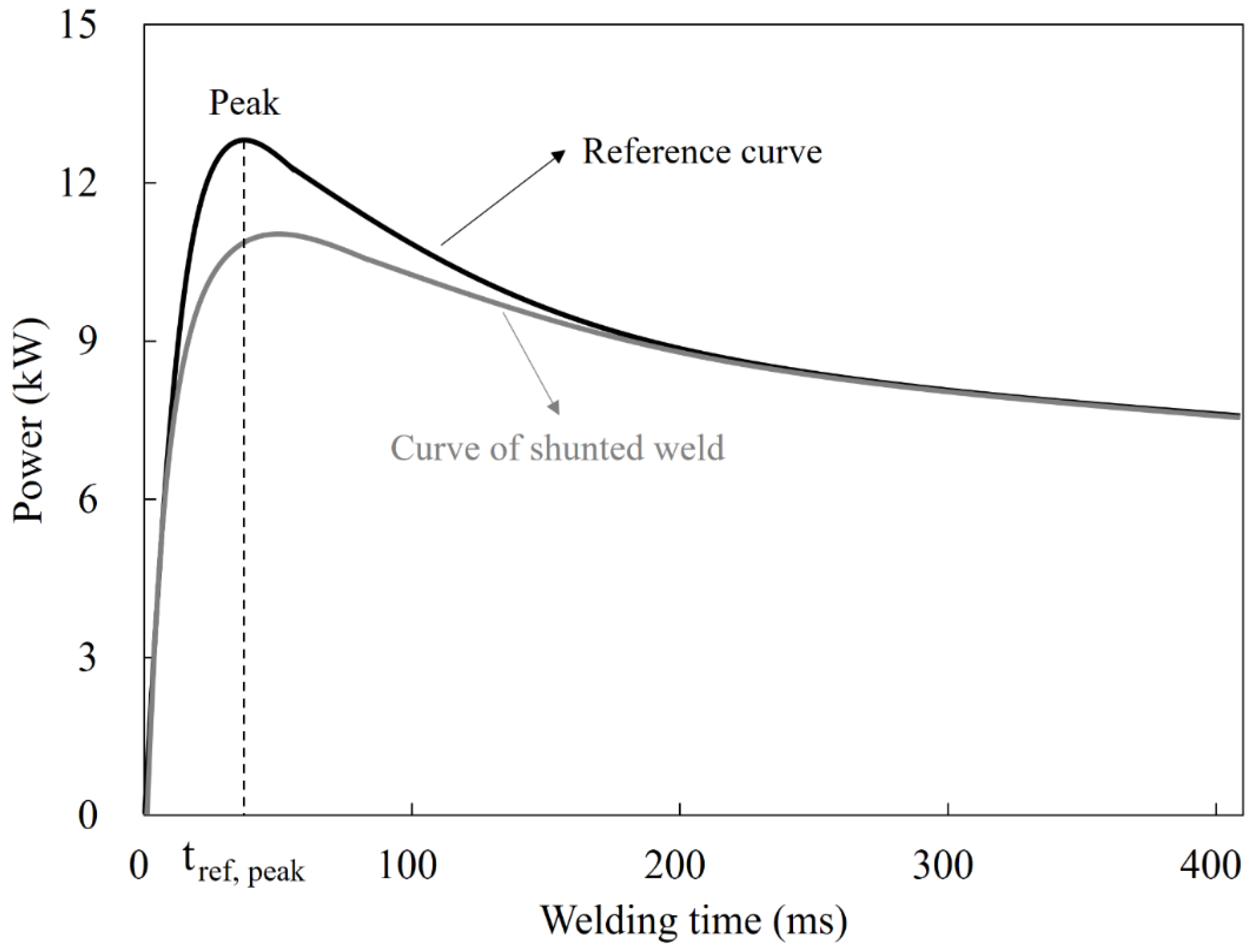
The welding power was measured over time for various weld pitches under a constant 7.5 kA welding current, a 410 ms welding time, and a 3.5 kN electrode force (reference welding conditions) to determine the effects of weld pitch on welding power. Figure 8 shows these relationships. For weld pitches of 10–40 mm, the power curve peak decreased, and was delayed as the weld pitch decreased, relative to the shunt weld. During short-pitch welding, the shunt weld formed a parallel electrical path that increased the shunting effect as the weld pitch decreased. Conversely, the shunting effect decreased as the weld pitch increased. For weld pitches greater than 45 mm, the power curves were nearly identical to those of the shunt weld. After the welding power peaked, the differences among the power curves gradually decreased until they converged. This phenomenon was likely caused by the reduction of both contact resistance and bulk resistance in the shunted weld after the dynamic resistance β-peak [17], which reduced the shunting effect.
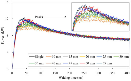
Figure 8.
Welding power over time for various weld pitches under a constant 7.5 kA welding current, a 410 ms welding time, and a 3.5 kN electrode force (reference welding conditions).
A new parameter was used in this study to estimate the weld pitch, minimize the monitoring time, and maximize the welding control time, as seen in Figure 7. The heat input ratio was defined as the ratio of the shunted welding heat input to the reference (shunt) welding heat input until the reference power curve peak and formulated as follows:
where Pshunted and Pref are the shunted and reference welding powers, respectively, and tref, peak is the time at which the reference power curve peaks. Figure 9 graphically depicts this parameter. The use of the heat input ratio accurately apportioned the monitoring and welding control times, resulting in shorter monitoring and longer welding control times.
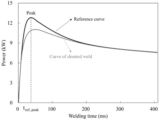
Figure 9.
Heat input ratio parameter.
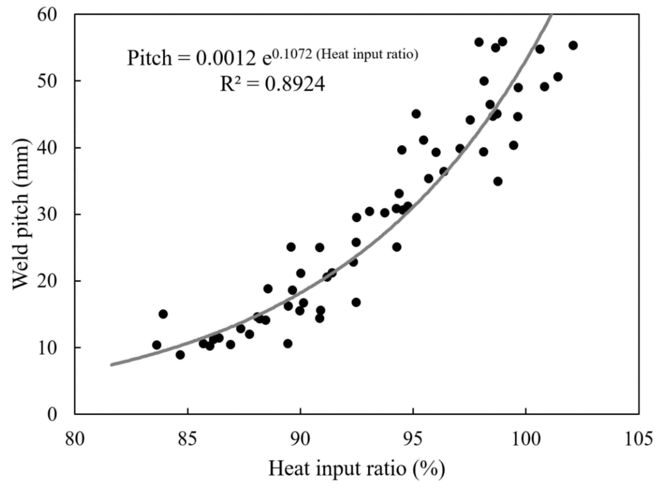
The relationship between the weld pitch and the heat input ratio was investigated to estimate the weld pitch. The following exponential model was developed based on this relationship:
This exponential model had a coefficient of determination (R2) of 0.8924, and was assumed to effectively estimate the weld pitch. Figure 10 graphically depicts this relationship.
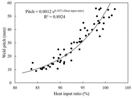
Figure 10.
Exponential model used to estimate the weld pitch as a function of the heat input ratio.
4.2. Heat Input Compensation Estimation
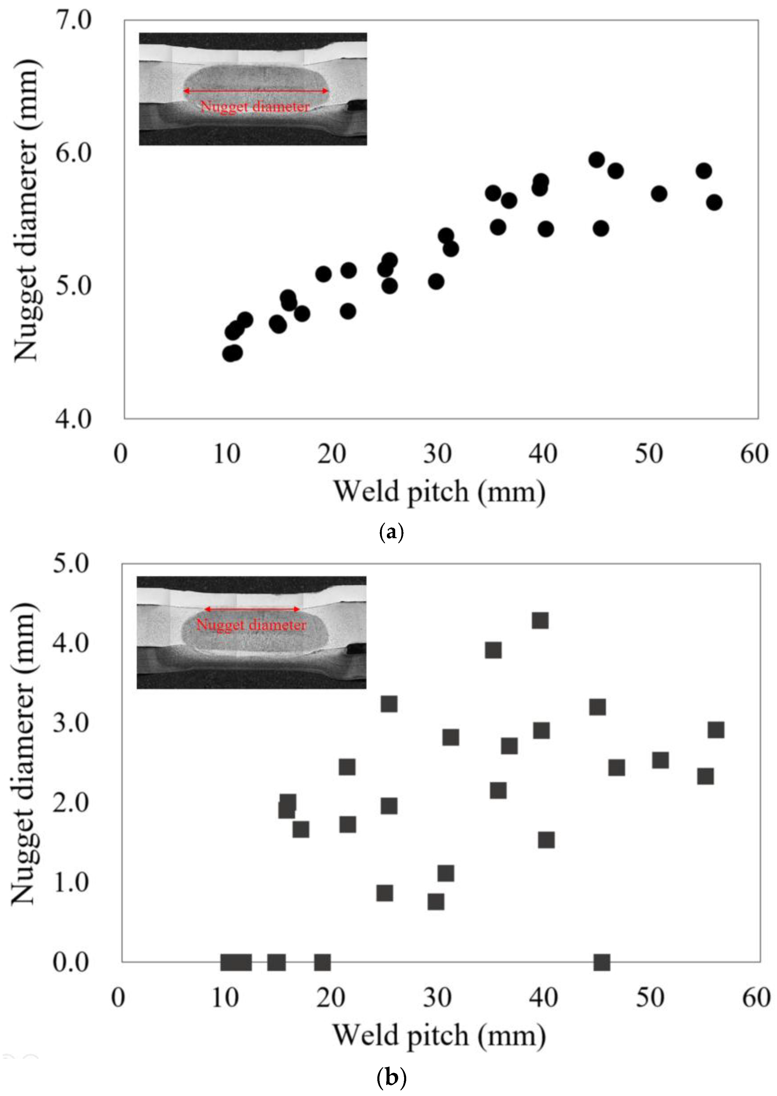
The heat input compensation in response to the shunting effect was estimated based on the nugget diameter. The effects of shunting and weld pitch on the nugget diameter were initially investigated. In this study, two types of nugget diameter were defined and used: nugget diameter between SGACEN and CP1180 (SGACEN-CP1180 nugget diameter) and maximum nugget diameter (CP1180-DP980 nugget diameter). Figure 11 shows the nugget diameters as a function of the weld pitch. The shunting effect decreased as the weld pitch increased. The CP1180-DP980 and SGACEN-CP1180 nugget diameters also increased. Consistent with prior observations, the nugget diameters converged for weld pitches greater than approximately 45 mm. The CP1180-DP980 nugget diameter was larger with smaller deviations, relative to the SGACEN-CP1180 nugget diameter. The higher thickness and resistivity of the CP1180 and DP980 materials resulted in a higher resistance and concentration of the heat input (joule heat) [27,28] relative to the SGACEN material. The CP1180-DP980 nugget diameter was assumed to best reflect the relationship between nugget growth and heat input, and was, therefore, used to estimate the heat input compensation.

Figure 11.
Nugget diameter as a function of the weld pitch for the (a) CP1180-DP980 and (b) SGACEN-CP1180 layers.
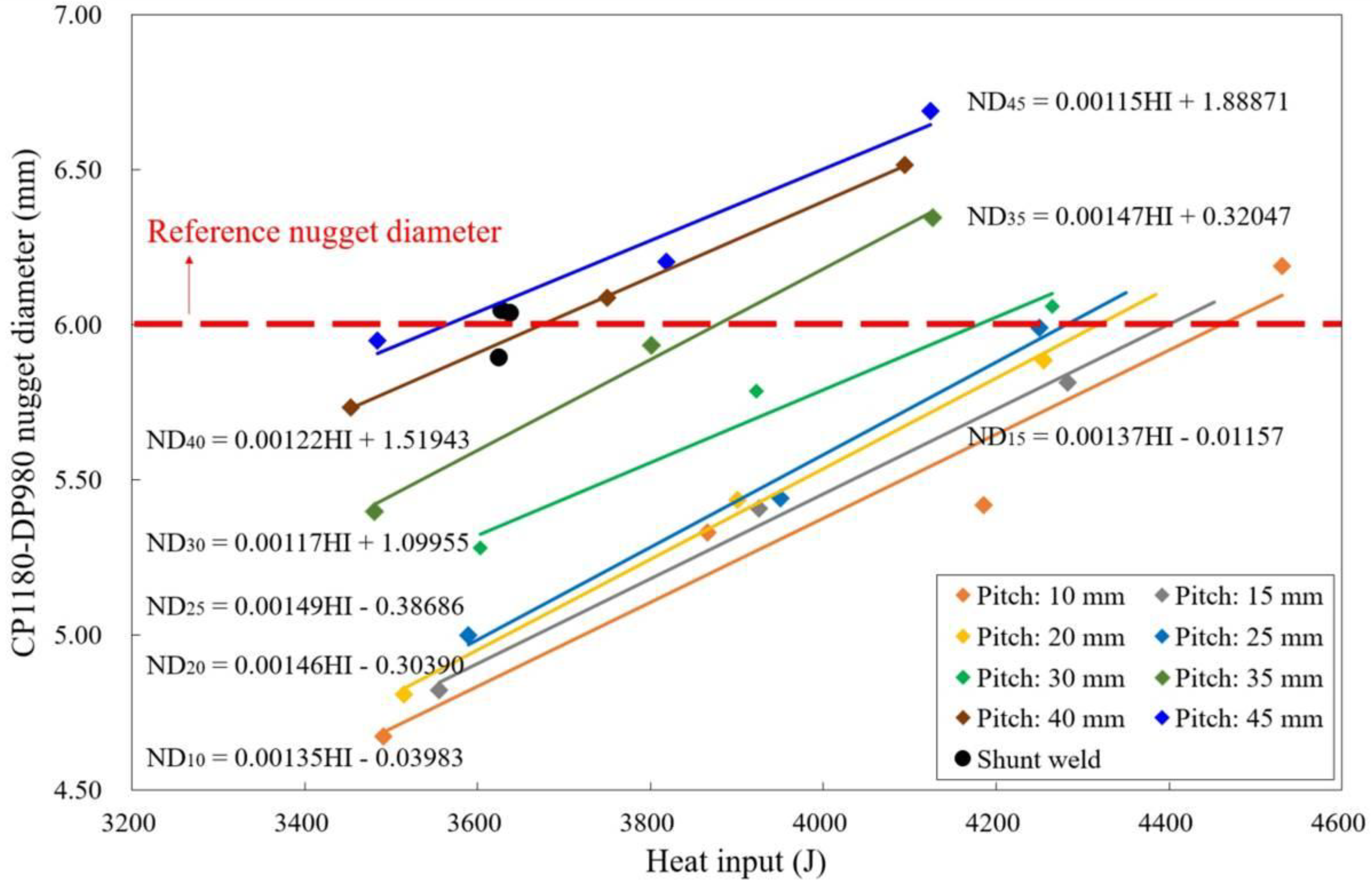
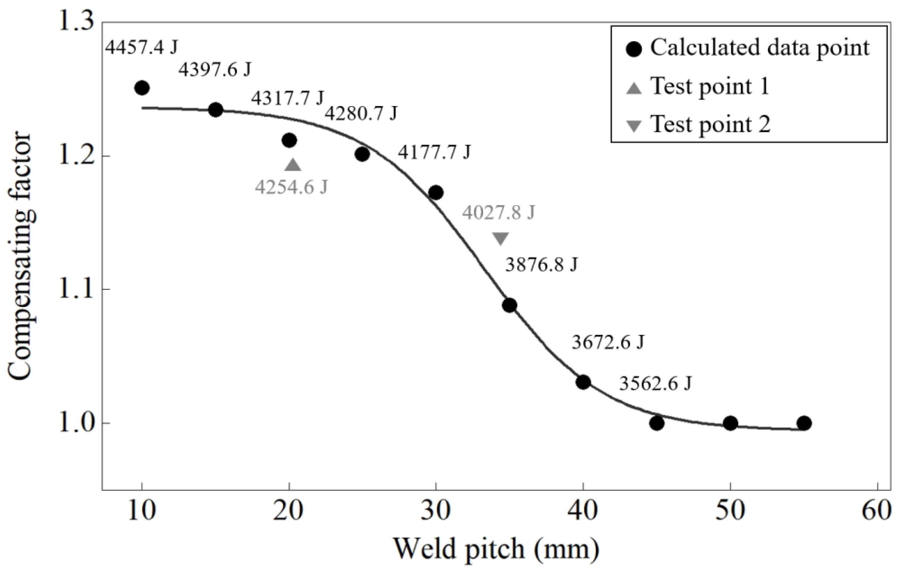
Figure 12 shows the CP1180-DP980 nugget diameter as a function of heat input for various weld pitches. For each of the weld pitches, the CP1180-DP980 nugget diameter increased as the heat input increased. At a constant heat input, the CP1180-DP980 nugget diameter increased as the weld pitch increased. The linear equations in Figure 12 were solved using a nugget diameter of 6 mm (similar to the shunt weld’s nugget diameter). The resultant heat input values were subsequently used to determine the related heat input compensating factors (CHI). Figure 13 shows this compensating factor as a function of weld pitch, as well as the calculated (data label), normalized (dot symbol) heat input values, and two test points to evaluate the relationship between the heat input and the weld pitch. The normalized values were obtained by dividing the calculated heat input values by the heat input value at a weld pitch of 45 mm. The CHI at weld pitches of 50 and 55 mm were assumed to be 1.0 because of the negligible shunting effect.

Figure 12.
CP1180-DP980 nugget diameter as a function of the heat input for various weld pitches.
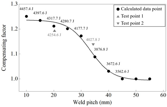
Figure 13.
Heat input compensating factor (CHI) as a function of weld pitch and the calculated (data label), normalized (dot symbol) heat input values, and test points. The normalized values are obtained by dividing the calculated heat input values by the heat input value at a pitch of 45 mm.
A logistic growth model was used to estimate the heat input compensation because this model form best reflected the relationship between CHI and the weld pitch and the convergence phenomenon at weld pitches greater than 45 mm. Furthermore, this converging model form prevented the calculation of excessively high heat input values when the estimated shunting effect was severe. These characteristics had the advantage of providing stability to the welding process. CHI and the associated heat input compensation (HItarget) were estimated as follows:
where Cuser is a user factor, and HIshunt weld is the heat input of the reference weld. In addition, test points 1 (maximum nugget diameter = 5.89 mm) and 2 (maximum nugget diameter = 6.19 mm), which did not have a nugget diameter of exactly 6.0 mm because of experimental limitations, were used to validate the relationship shown in Figure 13. Considering the difference in the nugget diameter, these two test points were considered to suitably follow the relationship between the heat input and the weld pitch. Although the prediction models for the weld pitch and CHI were considered appropriate, these formulations may not be widely transferrable because of the unique experimental conditions (e.g., test materials, material layers, welding conditions, electrode degradation, etc.) considered in this study. Cuser was included to address this limitation by allowing the users to adjust HItarget. Cuser can be determined by trial and error or can be optimized using optimization methods such as design of experiment (DOE).
4.3. Heat Input Compensation Supply Strategy
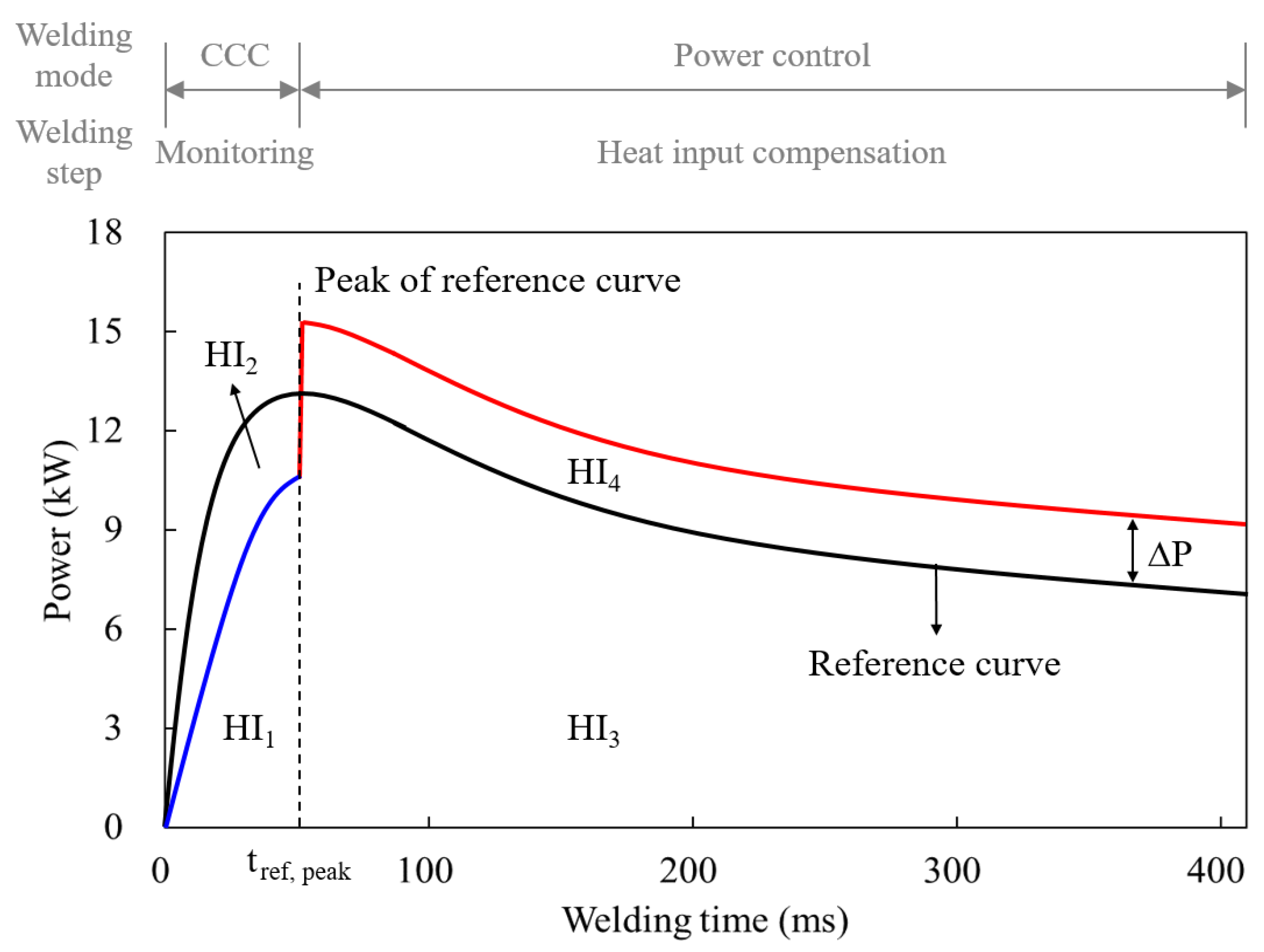
Figure 14 shows the heat input compensation (HItarget) supply strategy proposed in this study for the welding process. CCC welding was performed during the initial monitoring step. The welding current and voltage were measured at 0.5 ms intervals, while the welding power and the heat input were subsequently calculated. The monitoring step ended and the estimation step began when tref, peak was reached. The heat input ratio, weld pitch, CHI, and HItarget were estimated using the measured welding power and stored reference power and Equations (5)–(8). During the final heat input compensation step, the welding parameters were adjusted to supply HItarget over the remaining welding time. The constant power value (∆P) was specifically added to the previously stored reference power value at each 0.5 ms welding cycle after tref, peak. Power control was then used over a given welding time to produce a newly calculated power value. ∆P was calculated using the following formulations:
where Pmeasured and Preference are the measured and reference welding powers, respectively; tend is the reference welding time; and HI1, HI2, HI3, and HI4 are the heat inputs graphically defined in Figure 14. HI1 is the heat input up to tref, peak during the adaptive welding; HI2 is the heat input value obtained by subtracting HI1 from the heat input up to tref, peak during the reference welding; HI3 is the heat input from tref, peak to tend during the reference welding.
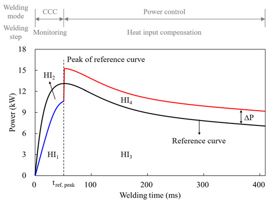
Figure 14.
Relationship between the β-peak and the monitoring and welding control times.
5. Experimental Validation Results
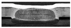
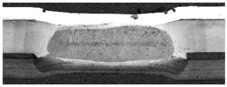
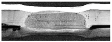
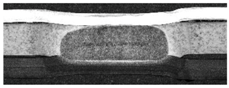
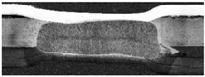
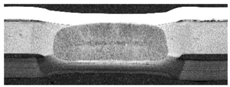
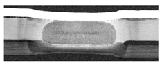
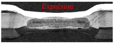
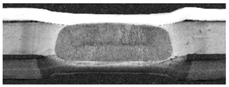
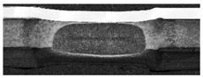
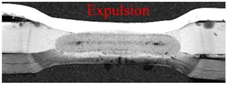
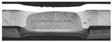
Four short-pitch spot welds were sequentially produced using conventional and proposed adaptive RSW welding methods to evaluate the performance of the proposed reference-based adaptive welding method and system. The Cuser values of 1.0 and 0.9 were used for the proposed adaptive welding method. Table 3 compares the weld pitch, heat input, and nugget diameter using these methods and includes cross-sectional images of the welds. In each case, the target weld pitch was 10.0 mm, but inexact adjustments led to random pitch effects. For the proposed adaptive RSW welding method, the errors of estimation for the weld pitch between the first and second welds were less than 10%: 6.87% at Cuser = 1.0 and 4.16% at Cuser = 0.9, which were much smaller than the variation of the data shown in Figure 10 (scatter plot). The weld pitch estimated between the second and third and third and fourth welds had larger relative errors because of the adjacent weld effects. Regarding the heat input and the nugget diameter, the conventional method produced lower heat inputs and smaller nugget diameters in the shunted welds (welds 2–4) attributable to the shunting effect. The CP1180-DP980 nugget diameters for the shunted welds were reduced by approximately 20%, and none reached the SGACEN-CP1180 faying surface. Comparatively, the proposed adaptive RSW method with Cuser = 1.0 had higher heat inputs and larger nugget diameters in the first shunted weld (weld 2) relative to the shunt weld (weld 1). This result was attributed to the adaptive process control described in Section 4. However, expulsion occurred in the third and fourth welds because of excessive heat energy supplied to the welds after tref, peak. For the proposed adaptive RSW method with Cuser = 0.9 (intended to prevent excessive heat input), the CP1180-DP980 nugget diameter in the first shunted weld (weld 2) slightly decreased relative to the shunt weld (weld 1), but increased more than 10% relative to the shunt weld produced using the conventional RSW method. The SGACEN-CP1180 nugget diameter in the first shunted weld (weld 2) decreased by less than 1% relative to the shunt weld (weld 1).
Table 3.
Comparison of various weld pitch, heat input, and nugget diameter parameters using conventional and proposed adaptive RWS methods.
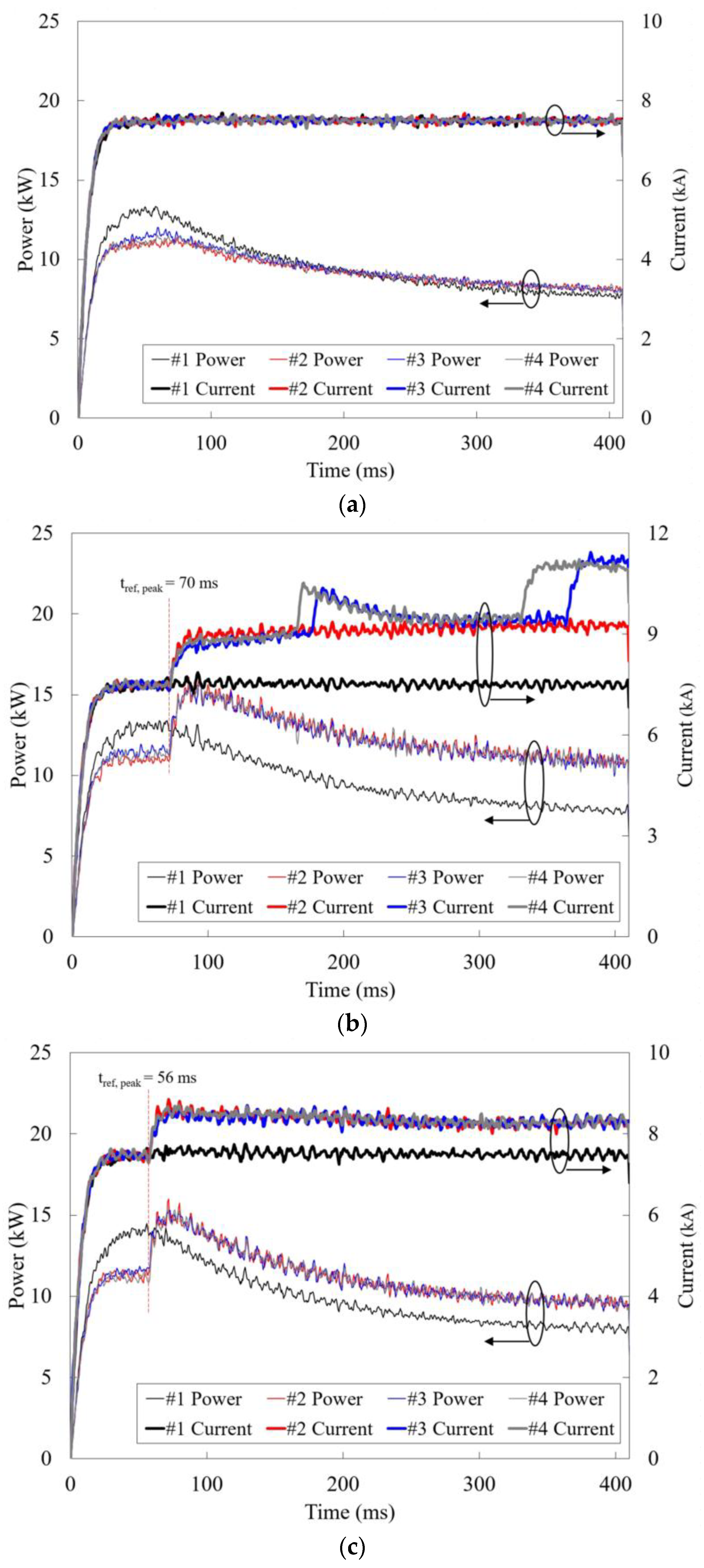
Figure 15 graphically illustrates the differences among the conventional and proposed adaptive RSW welding methods by presenting the measured welding current and power over time and for each of the four welds. When using the conventional RSW method, shown in Figure 15a, the welding power magnitude decreased as the number of welds increased because of the shunting effect. Alternatively, the proposed adaptive RSW method used CCC to monitor the welding signal up to tref, peak and used power control to compensate for the heat input loss. The current after tref, peak resembled a stepped constant-current function, but this waveform resulted from the power control. The sudden increases in current in Figure 15b were attributable to the expulsion events. Based on these collective results, the proposed reference-based adaptive RSW method and system were determined to be effective in reducing the shunting effect in the short-pitch RSW process.
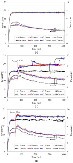
Figure 15.
Welding current and power over time and for each of the four welds measured during (a) conventional RSW; (b) proposed adaptive RSW with Cuser = 1.0; and (c) proposed adaptive RSW with Cuser = 0.9.
6. Conclusions
This study developed a reference-based adaptive RSW method intended to reduce the shunting effect and a related RSW system with combined power and current control capabilities that implements this adaptive method. The notable developments and outcomes from this study are as follows:
- The proposed adaptive RSW method and system reduced the shunting effect by compensating for the associated heat input loss using weld pitch estimates. Based on the relationship between the weld pitch and the welding power, the heat input ratio was used as a new parameter for estimating the weld pitch. This parameter decreased the monitoring time and increased the welding control time to support the adequate heat input compensation. An exponential model was developed to estimate the weld pitch as a function of the heat input ratio and subsequently implemented in the system’s controller.
- In addition, a logistic growth model was developed to estimate the heat input compensating factor (CHI) (used for calculating the heat input compensation) based on the nugget diameter, heat input, and weld pitch. This model not only estimated the heat input compensation factor, but also contributed to the stability of the welding process. A unique user factor (Cuser) was included to support application under different welding conditions (e.g., with different materials, material combinations, surface conditions, etc.).
- The unique heat input compensation supply strategy proposed herein distributed the calculated heat energy over a given welding time. This strategy used power control with a modified reference power curve.
- The experimental results intended to validate the proposed adaptive RSW method and system indicated that the proposed system effectively reduced the shunting effect and produced an improved nugget shape relative to conventional RSW method results. The nugget diameter can be maintained at a size similar to a shunt weld by proportionally increasing the heat input with the weld pitch. Therefore, the proposed welding process is considered to improve the mechanical performance of multi-spot welded panel structures, such as tensile shear strength and fatigue strength, based on the research results of Kulkarni [29] and Lee [30], which showed that the mechanical performances of a multi-spot welded panel was improved with the increase of the number of weld spots.
This study uniquely resulted in the development of both a reference-based adaptive RSW method intended to reduce the shunting effect and a related RSW system with combined power and current control capabilities that implements this adaptive method. Building upon this study’s advances, future research should consider the transferability of these developments under different welding conditions (e.g., with different materials, material combinations, surface conditions, etc.).
Funding
This research received no external funding.
Conflicts of Interest
The author declares no conflict of interest.
References
- Goldberg, P.K. The effects of the corporate average fuel efficiency standards in the US. J. Ind. Econ. 1998, 46, 1–33. [Google Scholar] [CrossRef]
- Kang, M.; Jeon, I.-H.; Han, H.N.; Kim, C. Tensile–shear fracture behavior prediction of high-strength steel laser overlap welds. Metals 2018, 8, 365. [Google Scholar] [CrossRef]
- Spena, P.R.; Rossi, S.; Wurzer, R. Effects of welding parameters on strength and corrosion behavior of dissimilar galvanized Q&P and TRIP spot welds. Metals 2017, 7, 534. [Google Scholar] [CrossRef]
- Hayat, F.; Sevim, I. The effect of welding parameters on fracture toughness of resistance spot-welded galvanized DP600 automotive steel sheets. Int. J. Adv. Manuf. Technol. 2012, 58, 1043–1050. [Google Scholar] [CrossRef]
- Sherwood, C.P.; Mueller, B.C.; Nolan, J.M.; Zuby, D.S.; Lund, A.K. Development of a frontal small overlap crashworthiness evaluation test. Traffic Inj. Prev. 2013, 14 (Suppl. 1), S128–S135. [Google Scholar] [CrossRef] [PubMed]
- Nguyen, P.T.L.; Lee, J.Y.; Yim, H.J.; Lee, S.B.; Heo, S.J. Analysis of vehicle structural performance during small-overlap frontal impact. Int. J. Autom. Tech. 2015, 16, 799–805. [Google Scholar] [CrossRef]
- Yu, J.; Shim, J.; Rhee, S. Characteristics of resistance spot welding for 1 GPa grade twin induced plasticity steel. Mater. Trans. 2012, 53, 2011–2018. [Google Scholar] [CrossRef]
- Oikawa, H.; Murayama, G.; Hiwatashi, S.; Matsuyama, K. Resistance spot weldability of high strength steel sheets for automobiles and the quality assurance of joints. Weld. World. 2007, 51, 7–18. [Google Scholar] [CrossRef]
- Challenges and Advances in Welding of a New Generation of High Strength Steels. Available online: http://awo.aws.org/wp-content/uploads/2014/RWMA/ChallengesandAdvancesinWeldingofNewGenerationofHighStrengthSteels_TVNataleMKimchiandJGould.pdf/ (accessed on 24 August 2018).
- Yu, J.; Choi, D.; Rhee, S. Improvement of weldability of 1 GPa grade twin-induced plasticity steel. Weld. J. 2014, 93, 78–84s. [Google Scholar]
- Yu, J. New methods of resistance spot welding using reference waveforms of welding power. Int. J. Precis. Eng. Manuf. 2016, 17, 1313–1321. [Google Scholar] [CrossRef]
- Duan, R.; Luo, Z.; Li, Y.; Zhang, Y.; Liu, Z.M. Novel postweld heat treatment method for improving mechanical properties of resistance spot weld. Sci. Technol. Weld. Join. 2015, 20, 100–105. [Google Scholar] [CrossRef]
- Taniguchi, K.; Matsuda, H.; Ikeda, R.; Oi, K. Heat distribution in welds by short-time high-current post-heating and its improving effect on cross tension strength: Development of resistance spot welding with pulsed current pattern for ultrahigh-strength steel sheets. Welding Int. 2016, 30, 817–825. [Google Scholar] [CrossRef]
- Sajjadi-Nikoo, S.; Pouranvari, M.; Abedi, A.; Ghaderi, A.A. In situ postweld heat treatment of transformation induced plasticity steel resistance spot welds. Sci. Technol. Weld. Join. 2018, 23, 71–78. [Google Scholar] [CrossRef]
- Shibuya, Y. Joining methods for the IMPREZA WRX STI. In Proceedings of the Joining in Car Body Engineering 2015, Bad Nauheim, Germany, 24–26 March 2015. [Google Scholar]
- Kuhn, R.M.; Mallick, P.K. Effect of weld pitch variation on the performance of a two-piece spot-welded body structure. SAE Tech. Pap. 2002. [Google Scholar] [CrossRef]
- Chang, H.S.; Cho, H.S. A study on the shunt effect in resistance spot welding. Weld. J. 1990, 69, 308–316. [Google Scholar]
- Wang, B.; Lou, M.; Shen, Q.; Li, Y.B.; Zhang, H. Shunting effect in resistance spot welding steels-Part 1: Experimental study. Weld. J. 2013, 92, 182–189. [Google Scholar]
- Li, Y.B.; Wang, B.; Shen, Q.; Lou, M.; Zhang, H. Shunting effect in resistance spot welding steels-Part 2: Theoretical analysis. Weld. J. 2013, 92, 231–238. [Google Scholar]
- Development of Short Pitch Resistance Spot Welding Technology. Available online: https://www.hondarandd.jp/point.php?pid=972&lang=en/ (accessed on 24 august 2018).
- Yu, J.; Faridh, M.; Park, Y.W. Adaptive resistance spot welding method that reduces the shunting effect. J. Manuf. Process. 2018, 35, 604–613. [Google Scholar] [CrossRef]
- Li, W.; Cerjanec, D.; Grzadzinski, G.A. A comparative study of single-phase AC and multiphase DC resistance spot welding. J. Maunf. Sci. E-T 2005, 127, 583–589. [Google Scholar] [CrossRef]
- Podržaj, P.; Simončič, S. Resistance spot welding control based on fuzzy logic. Int. J. Adv. Manuf. Technol. 2011, 52, 959–967. [Google Scholar] [CrossRef]
- Klopčič, B.; Dolinar, D.; Štumberger, G. Advanced control of a resistance spot welding system. IEEE Trans. Power Electr. 2008, 23, 144–152. [Google Scholar] [CrossRef]
- Cho, Y.; Rhee, S. Quality estimation of resistance spot welding by using pattern recognition with neural networks. IEEE T. Instrum. Meas. 2004, 53, 330–334. [Google Scholar] [CrossRef]
- Ling, S.-F.; Wan, L.-X.; Wong, Y.-R.; Li, D.-N. Input electrical impedance as quality monitoring signature for characterizing resistance spot welding. NDT E Int. 2010, 43, 200–205. [Google Scholar] [CrossRef]
- Yu, J. Effect of cover sheet on dissimilar three-steel sheets resistance spot welding. Int. J. Adv. Manuf. Technol. 2017, 89, 483–491. [Google Scholar] [CrossRef]
- Ikeda, R.; Okita, Y.; Ono, M.; Yasuda, K.; Terasaki, T. Development of advanced resistance spot welding process using control of electrode force and welding current during welding. Welding Int. 2014, 28, 13–20. [Google Scholar] [CrossRef]
- Kulkarni, P.P. Shear strength prediction of multi-spot welded lap shear specimen through experimentation and validation by FEM. Int. J. Eng. Res. Appl. 2014, 4, 80–87. [Google Scholar]
- Lee, H.; Kim, N. Fatigue life prediction of multi-spot-welded panel structures using an equivalent stress intensity factor. Int. J. Fatigue 2004, 26, 403–412. [Google Scholar] [CrossRef]
© 2018 by the author. Licensee MDPI, Basel, Switzerland. This article is an open access article distributed under the terms and conditions of the Creative Commons Attribution (CC BY) license (http://creativecommons.org/licenses/by/4.0/).