Abstract
The micro ablation characteristics of steel inflicted by the lightning currents and the influence of anti-corrosion coating on these characteristics are seldom investigated, even though fundamental to applications of steel. In this work, ablation tests on uncoated and coated mild steel plates were conducted with the 2 ms rectangular current simulating the component B of lightning currents. The macro-morphology, microstructure, and Vickers hardness of ablation zones were investigated systematically. The ablation characteristics and mechanisms of coated and uncoated steel were analyzed comparatively. It was found that the energy density of the 2 kA 2 ms rectangular current arc exceeded 106 W/cm2 causing the steel near the arc root melted within 2 ms and ablation formed. The width-depth-ratio of the ablated zone was 43.7 for uncoated plate, and only 7.5 for coated plate, since coating constricted the splashing effect of steel melt occurring on uncoated plate and confined the arc root. The metallographic microstructure and EBSD results showed the ablated zones of uncoated and coated steel both consisted of quenched martensite mixed with a handful of ferrite. There were fined equiaxed grains both in the fusion zone (FZ) and heat affected zone (HAZ) of uncoated plates whereas coarser columnar grains and fined equiaxed grains in the FZ and HAZ of coated plates, respectively. In the HAZ of uncoated plate, the average Vickers hardness of steel increased by 113%, while, in the HAZ and FZ of the coated plate, it increased by 209% and 136%, respectively.
1. Introduction
Lightning is the most hazardous natural events for industrial facilities, since lightning-triggered accidents of these facilities are of the highest frequency among all types of natural-caused accidents [1,2]. Storage tanks, such as the oil-storage tanks, are the most vulnerable industrial facilities that are threatened by the lightning [1,2]. More than 30% of the fire and exploration accidents of the steel-made tanks for oil storage are caused by direct lightning strikes [3]. The steel-made floating roof or external wall of oil-storage tanks can be heated, melted, or even be penetrated by the lightning currents due to the huge thermal effect of the lightning channel, and sparks that could ignite the oil vapor are generated [3,4]. The ablation characteristics of steel under direct lightning strikes are fundamental to the lightning protection of oil-storage tanks and other steel-made industrial facilities. Thus, it has been investigated for a long time in the field of lightning protection [5,6,7,8,9,10,11].
Investigations on the ablation characteristics of steel are carried out by the method of a simulated ablation test on steel plates with simulated lightning currents. The widely adopted simulated lightning currents, which are stipulated by the Society of Automobile Engineers (SAE) according to the features of natural lightning currents, consist of four components, i.e., the component A, B, C, and D [12]. Components A and D correspond to the return stroke currents of natural lightning, and components B and C correspond to the continuing currents. It has been recognized that the ablation damage of steel is mainly attributed to the continuing currents, since the arc of the continuing currents transfers more energy to the steel plate [6,8,9].
Among existing investigations on the ablation damage of steel struck by the continuing currents of lightning, a majority of attention have been focused on the ablation tests under the component C. These ablation damages, which can be observed directly with eyes, are in forms of the ablation crater on the steel plate or the penetration of the plate [6,8]. And, the ablation characteristics are evaluated by parameters including the melting volume of steel, the depth of the ablation crater and the rear-face temperature of the steel plate. In contrast, investigations on the ablation damage caused by the component B have been seldom conducted. Due to the high energy density of the current arc, the steel can be melted immediately and cooled down rapidly after being struck by the component B of the simulated lightning currents, which is similar with the process of welding, such as the tungsten insert gas (TIG) welding, and treatments of steel with high energy beams, such as laser or pulsed electron beams. Investigations have shown that martensite or austenite is produced in the fusion zone (FZ) and heat-affected zone (HAZ) of welding beads, and of the laser or pulsed electron beams radiated steel, and consequently alters the mechanical performance of steel [13,14,15,16]. Thus, the ablation damages in forms of microstructural and mechanical change of the steel, which cannot be evaluated by the above-mentioned macro parameters, are worth investigation. However, the micro-characteristics of the ablation damage have not been investigated and reported.
In industrial applications, the external walls of the steel-made storage tanks are painted with the coating materials to protect against corrosion and improve surface performance. Experiments of Y. K. Beller et al [9] and F. Moupfouma [11] show that the insulated coating can influence the arc behavior of the simulated lightning current on coated metal surface and consequently influence the surface morphology of the ablated zone. Whereas, the microstructure and mechanical characteristics of the ablated steel need to be further investigated to figure out the impact of anti-corrosion coating materials on the ablation mechanism of coated plate.
In the present investigation, ablation tests on the uncoated and coated mild steel plates have been conducted under the component B of the simulated lightning currents, which is the 2 ms rectangular current with amplitude of 2 kA as the SAE stipulated. The surface and sectional morphology, together with the metallographic and crystallographic microstructure, were investigated. The Vickers hardness cross-section of the ablated zones was measured. Based on the comparative analyses on these results, the characteristics and formation process of the ablated zone in the uncoated and coated plates were concluded.
2. Materials and Methods
2.1. Materials
Mild steel (Q235 steel) in hot-rolled condition was used in the ablation tests since it is widely applied in the storage tanks in China. The chemical composition (wt.%) of the as-received Q235 steel was 0.16C, 0.20Si, 0.61Mn, 0.019P, 0.023S, Fe balance. A typical anti-corrosion coating system on the external wall of storage tanks was painted on the coated samples. The anti-corrosion coating system consisted of three layers, i.e., the primer, the intermediate coating, and the top finish, of which the materials were the two-component epoxy zinc-rich coating, the micaceous iron oxide epoxy coating, and the two-component acrylic polyurethane coating, respectively. The film thickness of the three layers are 70 µm, 100 µm, and 70 µm, respectively. The surface resistivity of the coated plate was measured to be more than 1012 ohm, which indicated that the coating is insulated.
The as-received steel plates were 4 mm in thickness and were cut into smaller plates of 150 mm × 150 mm × 4 mm in dimension with machine tool to make samples for the ablation tests. To prepare uncoated samples, the smaller plates were polished with sandpaper of 400 meshes and 800 meshes, respectively. Then, dust on the surface of smaller plates were wiped off with absorbent cotton dipped in alcohol to avoid the dust’s influence on the interaction between current arc and uncoated sample surface.
To prepare coated samples, the smaller plates were pre-treated with a grit-blasting device (BT-1821, GuanTai Blasting Mechanic Co. Ltd, Qingdao, China). Then, the primer, the intermediate coating and the top finish were painted on these plates in sequence with high-pressure airless spraying treatment (GPQ-6C Changjiang Technology Co. Ltd, Chongqing, China). After each layer of coating being sprayed, the plates were settled in air for 5~6 h to ensure that the layer solidified completely. After being painted, the coated samples were wiped with absorbent cotton dipped in alcohol to eliminate dust as well.
2.2. Ablation Test Methods
The simulated lightning ablation tests have been conducted with a testing system, of which. the schematic diagram is shown in Figure 1. As the SAE stipulated, the 2 ms rectangular current was adopted to be the component B of the simulated lightning currents [12], and the ablation tests were conducted under the currents with amplitudes ranging between 1 kA to 2 kA. The 2 ms rectangular current was generated by the multi-waveform multi-pulse impulse current generator developed by our laboratory. The test current was measured by converting it into voltage with a resistance divider. The measured voltage waveform, which is equal to the current waveshape, is shown in Figure 2. The tungsten and copper electrode (W80) was used. As illustrated in Figure 1, the electrode tip consisted of an ellipsoidal dome and a conical body. The ellipsoidal dome was the front end of a ellipsoidal sphere, of which the long and short axi was 5 mm and 4 mm, respectively, as marked in Figure 1. The test plate was placed erectly. The electrode was fixed perpendicularly to the test plate. In order to keep the consistency of experimental results, the distance between the electrode tip and the test plate was fixed to be 5 mm with an insulated fixing device. When the 2 ms rectangular current was generated, the air gap between the electrode tip and the test plate was breaked down and the electric arc established between the air gap. The maximum temperature of the electric arc exceeded 3000 °C [10], which induced the ablation of the test plates.

Figure 1.
The schematic diagram of the testing system.
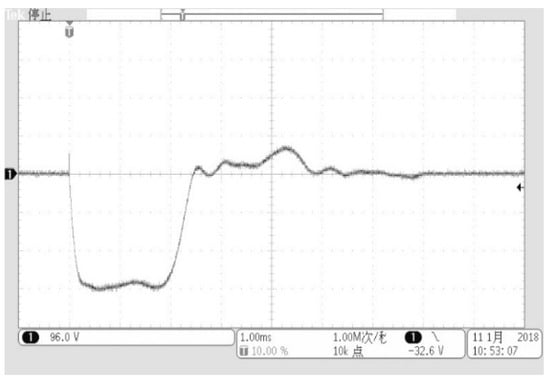
Figure 2.
The waveform of the 2 ms rectangular current with amplitude of 2 kA applied in the ablation tests.
2.3. Characterization Methods
The morphological inspection on the surface of the ablated zone was conducted with a stereoscope (Leica M125, Wetzalr, Germany). Then, the ablated zone was cut through across its center for the sectional sample. The metallographic microstructure of the sectional sample was observed with an optical misroscope (OM, Leica DM400, Wetzalr, Germany) and a scanning electron microscope (SEM, Tescan VEGA 3 - XMU, Brno, Czechia). And, the metallographic specimens were etched with 4% nital solution (4mL HNO3 and 96 mL C2H5OH). The electron backscattered diffraction (EBSD, VEGA 3 - XMU, Czechia) examination was carried out on the sectional sample and the data were analysed with the HKL Channel 5 software (version 5.0.9.0, Oxford Instruments, Abingdon, UK). The Vickers hardness of the sectional sample was measured using the micro-hardness tester (Zwick/Roell Zhu, Ulm, Germany) with a load of 50 g and a dwell time of 10 s.
3. Results
3.1. Macro-Morphology of the Ablation Zone
3.1.1. Uncoated Plate
The surface morphology of the uncoated plate inflicted by the 2 ms rectangular current with amplitude of 2 kA is shown in Figure 3a. The center of the splashing area O is regarded as the arc attachment point on the uncoated plated surface. As shown in Figure 3a, the surface of the ablated zone is characterized by the splashing morphology. The total splashing area approximates a circle with the diameter of 10.2 mm, of which the external boundary is marked with a red dashed line. Inside the splashing area, there are two obvious boundaries dividing the area it into three parts. In the central part that is encircled by the boundary 1, the surface of the steel plate is with metallic lustre and slightly uneven, which indicates that the steel near the arc attachment point has melted then re-solidified. In the part between the boundary 1 and 2, the steel surface gets brown and splashed steel spattering scatters. In the part between the boundary 2 and 3, there is splashed steel spattering as well, whereas the colour of the surface is different. The splashing morphology suggests that the melted steel near the arc attachment point has been splashed outward and re-solidified on the plate surface, forming the metal spattering.
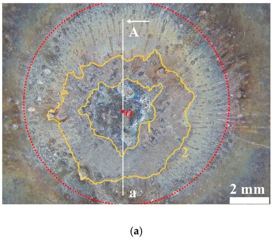
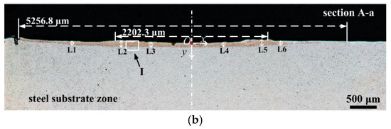
Figure 3.
The (a) surface morphology and (b) metallographic section morphology of the ablated zone on the uncoated plated inflicted by the 2 kA current (x is the direction along the plate surface).
The sectional metallographic morphology of the ablated zone, which was obtained by cutting the plate through the A-a line in Figure 3a, is shown in Figure 3b. The middle point O corresponds to the arc attachment point O marked in Figure 3a. As illustrated in Figure 3b, the ablated zone is band-shaped observed from the section view and the thickness of the band-shaped zone differs along the direction of the plate surface (x). At some representative locations marked in Figure 3b, the thicknesses of the ablated zone have been measured and are tabulated in Table 1.

Table 1.
Thickness (µm) of the ablated zone at locations marked in the sectional metallographic morphology of the uncoated and coated plates.
At locations 2 and 5, the thickness of the ablated zone is higher than that at other locations. The thickness decreases gradually from the location 2 and 5 to the left and right ends of the zone, respectively. It indicates that the ablation effect of the arc gets weak gradually with the distance from the arc root increasing. The horizontal length of the band-shaped zone is measured to be 5256.8 μm and approximately equals to the distance from one side to the opposite side of the boundary 2, which is shown in Figure 3a. It suggests that, the steel under the splashing area outside the boundary 2 has not been ablated by the arc, although the surface morphology of the steel plate has changed in this area. Thus, the ablated zone is limited inside boundary 2.
In addition, the thickness of the ablated zone decreases gradually from both locations 2 and 5 to the middle point O. The horizontal distance between locations 2 and 5 is measured to be 2202.3 μm and approximately equals to the distance from one side to the opposite side of boundary 1. At the central part of the splashing area encircled by the boundary 1, the thickness of the ablated zone is thinner. It can be further inferred that a portion of the steel melt near the arc attachment point has been splashed outward from the center, which is in accordance with the surface morphology. Taking the horizontal length and the maximum thickness of the band-shaped zone as the width and depth of the ablated zone, respectively, the width-depth-ratio of the ablated zone is 43.7.
For the ablation zones of the uncoated plates inflicted by the currents with 1 kA, 1.2 kA, 1.5 kA, and 1.8 kA amplitudes, respectively, there are similar splashing morphology on the surface and band-shaped ablation zone on the section, which presents similar macro characteristics with the ablation zone induced by the 2 kA current. The size of the ablation zone surface increases with the current amplitude growing. The curve in Figure 4 shows the positive revelance between the current amplitude and the diameter of the boundary on the ablation zone surface, which is delineated with the red dashed line in Figure 3a.
Figure 4.
The relation curve between the current amplitude and the diameter of the boundary on ablation zones’ surface of uncoated and coated plates.
3.1.2. Coated Plate
Similaryly, the surface morphology of the coated plate inflicted by the 2 ms rectangular current is shown in Figure 5a and the sectional metallographic morphology, which was obtained by cutting the plate through the B-b line in Figure 5a, is shown in Figure 5b.
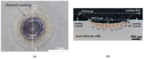
Figure 5.
The (a) surface morphology and (b) sectional metallographic morphology of the ablated zone on the coated plated inflicted by the 2 kA current (x is the direction along the plate surface, d is the maximum depth).
It can be seen from Figure 5a that a circular crater forms on the surface of the coated plate. The steel surface under the anti-corrosion coating system is revealed inside the crater, which indicates that the three layers of the coating system has totally melted and evaporated by the thermal effect of the arc. The revealed steel surface is slightly depressed downward. An annular area, in which the coating gets charred instead of being decomposed, appears surrounding the crater. Outside the annular area, the coating is relatively unaffected. And, there is no splashed steel spattering on the coated plate. The surface diameter of the crater is measured to be only 3.5 mm, which is smaller than the diameter of the splashing area on the uncoated plate.
The sectional morphology of the crater in the coating system are delineated in Figure 5b. It can be seen that the edge of the crater is slope, which suggests that the crater approximates a truncated cone. The top and bottom diameter of the crater is measured to be 3470.8 µm and 2297.8 µm, respectively. The ablated zone in steel is crescent-shaped from the section view, which suggests that a molten pool formed when the coated plate was inflicted by the arc of the 2 ms rectangular current. The upper boundary of the ablated zone is depressed downward compared with the original surface of the steel plate. Additionally, there is no splashed steel spattering on the surface of the coated plate as the Figure 5a has shown. Thus, it can be inferred that the evaporation of the melted steel has occurred during the ablation process. The thickness of the ablated zone at several representative locations marked in Figure 5b has been measured and is listed in Table 1 as well. The maximum depth of the ablated zone is measured to be 306.4 µm, and the width-depth-ratio of the ablated zone is 7.5.
As with the case of uncoated plates, the ablation zones induced by the 2 ms rectangular current with 1 kA, 1.2 kA, 1.5 kA, and 1.8 kA amplitudes present similar features with that induced by the 2 kA current, which are the ablation crater in coating material and the crescent-shaped ablation zone in steel material. The diameter of the boundary on the ablation zones surface equals to the bottom diameter of the crater, and its relation curve with the current amplitude is shown in Figure 4 as well.
3.2. Microstructure and EBSD Analysis
3.2.1. Microstructure
For the uncoated plate inflicted by the 2 kA current, the microstructure in the ablated zone I marked with a rectangular frame in Figure 3b is shown in Figure 6. The metallographic morphology in Figure 6a shows the microstructure transition from the ablated zone to the steel substrate, and Figure 6b,c further delineate the diverse microstructures in the two rectangular frames marked in Figure 6a, respectively. It can be seen from Figure 6 that the ablated zone includes the fusion zone (FZ) on the top and the heat affect zone (HAZ) under it. As shown in Figure 6b, there are many visible dendritic grains in the FZ, which is a typical solidification microstructure. There is lath martensite (M) mixed with a handful of ferrite (F) in the HAZ. As shown in Figure 6c, there is a dual phase region of martensite and α-ferrite (F) in the HAZ, which suggests that the temperature in this region was lower than the austenite transformation temperature, and only part of base metal was transformed during the ablation process. The content of martensite decreases gradually from the upper part to the lower part of the HAZ. The thickness of the FZ and the HAZ in Figure 6a is measured to be about 12.9 µm and 82.0 µm, respectively.
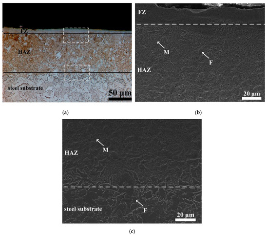
Figure 6.
The (a) microstructure observed with optical microscope (OM) in the ablated zone of uncoated plate and the microstructure observed with scanning electron microscope (SEM) in (b) the upper rectangular frame and (b) the lower rectangular frame marked in figure (a). (FZ represents the fusion zone; HAZ represents the heat affected zone; M represents martensite and F represents ferrite.).
For the coated plate inflicted by the 2 kA current, the ablated zones II and III, which are marked with reactangular frames in Figure 5b, are shown in Figure 7a,b, respectively. For the convenience of comparison, the metallographic microstructure of the steel substrate is shown in Figure 7c. As illustrated in Figure 7, the ablated zone is composed of the FZ and the HAZ. In the labelled FZ, there are lath martensite (M), massive ferrite (MF), and acicular ferrite (AF). And, the columnar grain boundaries, from which the martensite grows, can be observed. In the HAZ, the microstructure is characterized by lath martensite and massive ferrite with smaller size than that in the FZ. There was also no appearance of columnar grain boundaries. The interface between the FZ and the HAZ, which is marked with the white dashed line, is in parallel with the interface between the HAZ and the steel substrate. The distance between the white and black dashed lines is regarded to be the thickness of the HAZ and is measured to 89.7 µm. The thickness of the FZ is measured to be 199.5 µm.
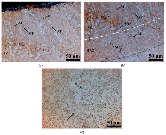
Figure 7.
The metallographic microstructure in the (a) ablated zone II, (b) the ablated zone III and (c) the steel substrate. (MF represents massive ferrite and AF represents acicular ferrite.).
3.2.2. EBSD Analysis
The crystallographic characteristics of the ablated zones in the uncoated and coated plates were investigated. In the ablated zones of the uncoated and coated plates, the phase constitutions are both bcc and FeC3, which is in accordance with the microstructure observation result with the optical microscope and scanning electron microscope.
Figure 8a,b show the EBSD maps of the ablated zones in the uncoated and coated plates, respectively, of which the vision fields correspond to the locations shown in Figure 6a and Figure 7b, respectively. Figure 8c further delineates the ablated zone that is partly presented in the upper part of Figure 8b. The low angle grain boundaries (LAGBs) with misorientataion angle between 3° to 15° and the high angle grain boundaries (HAGBs) with misorientataion angle exceeding 15° are marked with white and black lines, respectively.
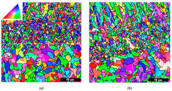

Figure 8.
Electron backscattered diffraction (EBSD) maps of the (a) ablated zone in uncoated plate, (b) and (c) ablated zones in coated plate.
Figure 8a shows that, for uncoated plate, there are fined equiaxed grains both in the FZ and the HAZ of the ablated zone, and, in contrast, coarser equiaxed grains in the steel substrate. The average size of the equiaxed grains and the original equiaxed grains are measured to be 3.5 µm and 10.8 µm, respectively. The crystallographic microstructure in the ablated zone is homogeneous, and for the convenience of discussion, the ablated zone is regarded as the fine-grained zone I (FGZ-I).
According to Figure 8b, there are columnar grains in the FZ, fined equiaxed grains in the HAZ and coarser equiaxed grains in the steel substrate, in sequence. The two paralleled boundaries between the three parts are marked with white dashed lines. It can be seen that the growing direction of the columnar grains is perpendicular with the two boundaries, indicating that the grains grow preferentially along the direction of thermal conduction. The average size of the equiaxed grains in the HAZ is measured to be 3.5 µm as well. Similarly, the FZ and the HAZ of the ablated zone in coated plate are defined as the columnar-grained zone (CGZ) and the fine-grained zone II (FGZ-II), respectively.
In the CGZ shown in Figure 8c, smaller equiaxed grains appear between the large columnar grains and grains with low angle misorientation boundaries exist inside the large columnar grains. The fraction of LAGBs in the zones including the CGZ and FGZ-II of the coated plates, the FGZ-I of the uncoated plate and the steel substrate have been measured and shown in Table 2. It can be known that, the fraction of LAGBs in the steel substrate is the lowest and in the CGZ is the highest.
Table 2.
The fraction of the low angle grain boundaries (LAGBs) in the ablated zone in uncoated and coated plates and the steel substrate.
3.3. Vickers Hardness
For coated and uncoated plates, the Vickers hardness profiles of the steel have both been measured cross the section of the plate from the ablated zone to the steel substrate. The schematic distribution of the measured points on the section of the uncoated and coated plates is shown in Figure 9a and the Vickers hardness profiles are shown in Figure 9b. The horizontal axis in Figure 9b represents the vertical distance of the measured point from the surface of the ablated zone. Since the thickness of FZ in uncoated plate is too thin to measure the accurate value of the Vickers hardness, only the HAZ is marked on the Vickers hardness profile of the uncoated plate.
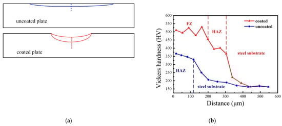
Figure 9.
The (a) schematic distribution of the measured points and (b) Vickers hardness profiles of the steel cross the section of the uncoated and uncoated plates.
It can be seen from the Figure 9b that, both for coated and uncoated plates, the Vickers hardness of the steel in the ablated zones is higher than that in the steel substrate. The Vickers hardness of the steel decreases sharply near the interface between the ablated zone and the steel substrate. Additionally, in the steel substrate area that is close to the ablated zone, the Vickers hardness of the steel is slightly higher than the Vickers hardness in the area that is distant from the ablated zone.
It can be seen from the Figure 9b as well that, for the ablated zone of the coated plate, the Vickers hardness of the steel in the FZ is higher than that in the HAZ. In the FZ, the value of the Vickers hardness ranges between 450 and 550 HV and fluctuates randomly at different measured points. In the HAZ, the value of the Vickers hardness ranges between 350 and 400 HV and varies slightly at different measured points. In addition, the Vickers hardness in the HAZ of the coated plate approximates that in the HAZ of the uncoated plate.
4. Discussion
4.1. Geometry of the Ablated Zones
As mentioned above, the diameter of the ablation zone’s surface boundary on uncoated plate is larger than that on coated plate at each current amplitude between 1 kA to 2 kA. In addition, the section of the ablated zone in the uncoated plate is band-shaped, while that in the coated plate is crescent-shaped. The width-depth-ratios of the ablated zone in the uncoated and coated plates inflicted by the current with 2 kA amplitude are 43.7 and 7.5, respectively. The differences in the geometry of the ablated zones indicate that the appearance of anti-corrosion coating system influenced the current arc behavior on sample surface and the ablation process of steel.
The arc of the 2 ms rectangular current simulating the lightning current was a type of plasma beam. With the current amplitude reaching 2 kA, the steel near the arc attachment point of coated and uncoated plates both melted within 2 ms after the test plates being struck, as confirmed by the macro ablation morphology on the surface of uncoated and coated plates.
Inside the arc channel, there was considerable temperature gradient along the radial direction of the arc channel inducing a radially outward force that balances with the radially inward electromagnetic force [10]. The higher the current amplitude was, the higher the electromagnetic force in the arc column and the greater temperature gradient were. At the arc attachment point on the uncoated plate, the current was dispersed into the steel, but the temperature gradient still existed. The force balance in the arc channel was broken at the arc attachment point. As a consequence, the radially outward force became the explosive force that splashed a portion of the steel melt away from the arc attachment point, which extended the distribution range of the steel melt on the plate surface and decreased the thickness of them. Thus, the ablated zone in the uncoated plate was band-shaped and shallow in depth.
However, the arc behavior on the coated plate was different from that on the uncoated plate. Since the coating system was insulated, the three layers of the coating system were broken down firstly when the coated plate was struck by the 2 ms rectangular current with amplitude of 2 kA. The finishing decomposition temperature of the epoxy and polyurethane, which are the base materials of the coating system, are 500 °C and 625 °C, respectively [17,18], while the temperature of the arc channel would exceed 3000 °C [9,10]. Thus, almost at the same time when they were broken down, the three layers of the coating system melted and decomposed by the thermal effect of the arc during the ablation process, which caused the formation of the crater in the coated plate. Since the well conductive steel was revealed inside the crater, the current was prone to flow in to the steel plate though the revealed steel surface and the arc root of the 2 ms rectangular current was limited inside the crater. As a consequence, the splashing effect was constricted, and the steel melt aggregated into a molten pool at the arc attachment point. During the duration of the 2 ms rectangular current, the surface of the molten pool suffered from the arc pressure, which was in proportion with the square of the current amplitude [19,20,21]. The amplitude of test current is high up to 2 kA, thus the surface of the molten pool was depressed downward and the ablated zone in the coated plate was crescent-shaped.
In general, it can be known that, during the ablation process, the steel melt was splashed away from the arc attachment point on the uncoated plate, whereas the splashing effect was restricted on the coated plate causing the formation of a molten pool, which lead to the different geometry of the ablated zones in uncoated and coated plates.
4.2. The Microstructure and Vickers Hardness in the Ablated Zones
As mentioned above, the metal melted within 2 ms after being struck by the arc of the 2 ms rectangular current, thus the formation of the final microstructure in the ablated zone was a synthetical result of the solidification and the solid-state phase change. In addition, this indicates that the energy density injected from the current arc to the test plate exceeded the order of 106 W/cm2, since it has been investigated that it takes 25 ms for the steel to be melted when the energy density is 106 W/cm2 [9,10]. According to the duration of the current and the energy density of the arc, it can be known that the metal ablation process is comparable to the surface re-melting treatment of steel via laser or pulsed-electron beam, of which the energy density ranges between 106 W/cm2 to 108 W/cm2 in general [16,22,23].
Quenched martensite mixed with a handful of ferrite both in the ablated zones of the uncoated and coated plates, as with the cases in investigations on the surface re-melting treatment [22,23,24,25]. Since the energy density of the current arc is over 106 W/cm2, the thermal gradient and cooling rate in steel are high enough for the appearance of quenched martensite. The carbon content of the steel adopted in the present investigation was 0.16%, and therefore the ferrite formed in the ablated zone, according to the iron-carbon phase diagram [26].
The depth of the ablated zone in uncoated and coated plates was deeper than the depth of the heat affected zones caused by the surface re-melting treatment with pulsed electron beams, which generally ranged between several micrometers to tens of micrometers [23,24,25]. The electron beams applied in surface re-melting treatment are pulsed and with typical pulse duration up to several microseconds [16,22], while the 2 ms rectangular current is a one-shot strike and the duration is much longer, which enabled the heat to accumulate in the steel during the whole ablation process and consequently cause deeper ablated zone.
Based on the above analysis on the morphology of the ablated zones in Section 4.1, it can be known that the coating influences the steel melt’s geometry and their dynamic behavior on the plate surface. This further caused the differences in the solidification processes of the steel melt and the crystallographic microstructure of the ablated zone between the uncoated and coated plates.
For the uncoated plate, there were fined equiaxed grains both in the FZ and the HAZ, while for the coated plate, there were columnar grains and fined equiaxed grains in the FZ and the HAZ, respectively. The fined equiaxed grains in the ablated zones were mainly attributed to the rapid cooling rate of the steel near the arc attachment point, since it is well known that the rapid cooling rate is a substantial factor for the formation of fined equiaxed grains [27], and the steel was cooled down rapidly during the ablation process. In addition, the refinement of grains was in accordance with the investigations showing that the size of martensite was refined in microstructure produced by surface re-melting treatment [16,27]. The columnar grains grew preferentially along the direction of the heat conduction in the FZ of the coated plate, as shown in the Figure 8b, since the growth of grains was driven by the thermal gradient inducing force.
As shown in Table 2, the fraction of LAGBs in the ablated zones of uncoated and coated plates were both higher than that in the steel substrate and the fraction in the FZ of coated plate is the highest. It probably related to the fact that the dislocation density in the ablated zones increased compared with the steel substrate, since it was reported that there was dislocation in the microstructure of the irradiated steel via the pulsed-electron beam [28,29]. The current amplitude was high up to 2 kA, thus the resultant force applied on the steel melt by the arc of the 2 ms rectangular current, which includes the arc pressure, the arc shear stress and the electromagnetic force, can be strong enough to drive serious flowing behavior in the molten pool [21] and influence the solidification process of the steel melt. In addition, the thermal gradient in the steel near the arc attachment was as high as that in the steel irradiated by the pulsed-electron beam. These probably were the reasons for the increased dislocation density in the ablated zones.
The Vickers hardness of steel in the ablated zones of uncoated and coated plates was both higher than that in the steel substrate as a result of the appearance of quenched martensite. In the HAZ of the uncoated plate, the average Vickers hardness of steel increased by 113%, while, in the HAZ and FZ of the coated plate, it increased by 209% and 136%, respectively. Both for uncoated and coated plates, the Vickers hardness decreased monotonically across the section of the ablated plates, which was distinct from the fluctuating Vickers hardness profiles cross the section of processed steel via pulsed-electron beam. The fluctuating Vickers hardness profiles is recognized to be caused by the shockwave propagated from the pulsed-electron beam into the steel [30,31]. Thus, the Vickers hardness profiles of the ablated zone in coated and uncoated plate decreasing monotonically indicated that the shockwave from the one-shot struck of the 2 ms rectangular current arc was not as serious as from the pulsed-electron beam.
5. Conclusions
Ablation tests on the uncoated and coated mild steel were conducted with the 2 ms rectangular current simulating the component B of the lightning current. The surface and cross-section morphology, the microstructure, and the Vickers hardness of the ablated zones in the uncoated and coated plates were investigated. Based on the results and discussions, the following conclusions were drawn:
- The energy density, which was injected from the arc of 2 ms rectangular current with 2 kA amplitude to the test plate, exceeded 106 W/cm2. Being struck by the arc, the steel in the uncoated and coated plates both melted instantaneously within 2 ms and then solidified rapidly, which resulted in the ablated zone.
- The coating constricted the splashing effect of steel melt, which was attributed to the explosive force induced by the thermal gradient at the arc attachment point on uncoated plate and confined the arc root in the ablated crater. Thus, the section of the ablated zone is band-shaped in uncoated plate and is crescent-shaped instead in coated plate. The width–depth ratios of the ablated zones in uncoated and coated plates were 43.7 and 7.5, respectively.
- The ablated zones of uncoated and coated plates were both characterized by the quenched martensite mixed with a handful of ferrite, the fined grains and the increased Vickers hardness, as with the cases in surface re-melting treatment of steel via laser or pulsed-electron beam. And, there was no crack both in the ablated zone of uncoated and coated plates.
- For the uncoated plate, equiaxed grains were found both in the FZ and HAZ. For the coated plate, equiaxed grains were found in the HAZ, and coarser columnar grains mixed with smaller equiaxed grains in the FZ. This was attributed to that the coating influenced the steel melt’s geometry and dynamic behavior on the plate surface, which consequently altered the solidification process of the steel melt.
- In the HAZ of uncoated plate, the average Vickers hardness of steel increased by 113%, while, in the HAZ and FZ of the coated plate, it increased by 209% and 136%, respectively. The Vickers hardness profiles of the uncoated and coated plates both decreased monotonically from the ablated zone to the steel substrate.
Author Contributions
Conceptualization, M.D. and Z.F.; methodology, M.D. and Y.L.; software, M.D. and J.L.; validation, M.D. Z.F. and Y.L.; formal analysis, M.D.; investigation, M.D.; resources, X.B.; data curation, J.L.; writing—original draft preparation, M.D.; writing—review and editing, M.D., Z.F. and Y.L.; visualization, M.D. and J.L.; supervision, Z.F. and X.B.; project administration, Z.F. and X.B.; funding acquisition, Z.F. and Y.L.
Funding
This research was funded by the National Natural Science Foundation of China grant number [51577117]. The APC was funded by the National Natural Science Foundation of China grant number [51577117].
Acknowledgments
We appreciate the support from SINOPEC Researching Institute of Safety Engineering for providing materials and accommodation during the experiments.
Conflicts of Interest
The authors declare no conflicts of interest.
References
- Renni, E.; Krausmann, E.; Cozzani, V. Industrial accidents triggered by lightning. J. Hazard. Mater. 2010, 184, 42–49. [Google Scholar] [CrossRef] [PubMed]
- Chang, J.L.; Lin, C.C. A study of storage tank accidents. J. Loss Prev. Process Ind. 2006, 19, 51–59. [Google Scholar] [CrossRef]
- Wu, D.Y.; Chen, Z. Quantitative risk assessment of fire accidents of large-scale oil tanks triggered by lightning. Eng. Fail. Anal. 2016, 63, 172–181. [Google Scholar] [CrossRef]
- Necci, A.; Argenti, F.; Landucci, G.; Cozzani, V. Accident scenarios triggered by lightning strike on atmospheric storage tanks. Reliab. Eng. Syst. Saf. 2014, 127, 30–46. [Google Scholar] [CrossRef]
- McEachron, K.B.; Hagenguth, J.H. Effect of Lightning on Thin Metal Surfaces. Trans. Am. Inst. Electr. Eng. 1942, 61, 559–564. [Google Scholar] [CrossRef]
- Kern, A.; Zischank, W. Melting effects on metal sheets and air termination wires. In Proceedings of the 19th International Conference on Lightning Protection, Graz, Austria, 25–29 April 1988. [Google Scholar]
- Fisher, R.J.; Schnetzer, G.H. Damage to Metallic Samples Produced by Measured Lightning Currents. Technical Report from NASA; 1991; pp. 1–10. Available online: https://ntrs.nasa.gov/search.jsp?R=19910023326 (accessed on 3 October 2018).
- Zischank, W.; Drumm, F. Reliable simulation of metal surface penetration by lightning continuing currents. In Proceedings of the 18th International Aerospace and Ground Conference on Lightning and Static Electricity, Williamsburg, VA, USA, 26–28 September 1995. [Google Scholar]
- Kostogorovabeller, Y. Physics of Interaction of Lightning Currents with Aluminum Sheets. J. Aircr. 2012, 49, 66–75. [Google Scholar] [CrossRef]
- Chemartin, L.; Lalande, P.; Peyrou, B.; Chazottes, A.; Elias, P.Q.; Delalondre, C. Direct effects of lightning on aircraft structure: Analysis of the thermal, electrical and mechanical constraints. Aerosp. Lab. 2012, 5, 1–15. [Google Scholar]
- Moupfouma, F. Aircraft Structure Paint Thickness and Lightning Swept Stroke Damages. SAE Int. J. Aerosp. 2013, 6, 392–398. [Google Scholar] [CrossRef]
- SAE Aerospace Recommended Practice 5412B—Aircraft Lightning Environment and Related Test Waveforms; Society of Automotive Engineers: Warrendale, PA, USA, 2013.
- Yan, J.; Gao, M.; Zeng, X.Y. Study on microstructure and mechanical properties of 304 stainless steel joints by TIG, laser and laser-TIG hybrid welding. Opt. Lasers Eng. 2010, 48, 512–517. [Google Scholar] [CrossRef]
- Syed, B.; Shariff, S.M.; Padmanabham, G.; Lenka, S.; Bhattacharya, B.; Kundu, S. Influence of laser surface hardened layer on mechanical properties of reengineered low carbon steel sheet. Mater. Sci. Eng. A 2017, 685, 168–177. [Google Scholar] [CrossRef]
- Lan, L.Y.; Qiu, C.L.; Zhao, D.W.; Gao, X.H.; Du, L.X. Analysis of microstructural variation and mechanical behaviors in submerged arc welded joint of high strength low carbon bainitic steel. Mater. Sci. Eng. A 2012, 558, 592–601. [Google Scholar] [CrossRef]
- Proskurovsky, D.I.; Rotshtein, V.P.; Ozur, G.E.; Markov, A.B.; Nazarov, D.S. Pulsed electron-beam technology for surface modification of metallic materials. J. Vac. Sci. Technol. A 1998, 16, 2480–2488. [Google Scholar] [CrossRef]
- Gou, J.; Tang, Y.; Liang, F.; Zhao, Z.; Firsich, D.; Fielding, J. Carbon nanofiber paper for lightning strike protection of composite materials. Compos. Part B Eng. 2010, 41, 192–198. [Google Scholar] [CrossRef]
- Duan, L. Thecrystallization Kinetic and Thermal Decomposition Behavior of Polyurethane. Master’s Thesis, Nanjing University of Science and Technology, Nanjing, China, 2012. (In Chinese). [Google Scholar]
- Lin, M.L.; Eagar, T.W. Pressures produced by gas tungsten arcs. Metall. Trans. B 1986, 17, 601–607. [Google Scholar] [CrossRef]
- Hiraoka, K.; Okada, A.; Inagaki, M. Effect of electrode geometry on maximum arc pressure in gas tungsten arc welding. Q. J. Jpn. Weld. Soc. 1985, 3, 246–252. [Google Scholar] [CrossRef]
- Meng, X.M.; Qin, G.L.; Zou, Z.D. Sensitivity of driving forces on molten pool behavior and defect formation in high-speed gas tungsten arc welding. Int. J. Heat Mass Transf. 2017, 107, 1119–1128. [Google Scholar] [CrossRef]
- Liu, J.L.; Zou, Z.R.; Su, B.R. Heat Process Treatment with High Energy Beam, 1st ed.; Machinery Industry Press: Beijing, China, 1997; pp. 80–110. [Google Scholar]
- Shao, T.M.; Lin, X.C.; Yuan, W.D. Microstructure of transition zone in 2Cr14 steel by laser surface remelting. Acta Metall. Sin. 2001, 37, 1040–1044. [Google Scholar] [CrossRef]
- Liu, Z.J.; Han, L.J.; Jiang, X.L.; Le, X.Y. Study on microstructures of pulsed electron beam remelted carbon steel 45. J. Aeronaut. Mater. 2005, 25, 20–24. [Google Scholar] [CrossRef]
- Tang, G.Z.; Luo, D.; Tang, S.W.; Mu, Q.; Wang, L.Q. The microstructure and properties of Cr alloying layer after surface alloying treatment induced by high current pulsed electron beam. J. Alloys Compd. 2017, 714, 96–103. [Google Scholar] [CrossRef]
- Cui, Z.Q.; Qin, Y.C. Metalogy and Heat Treatment, 2nd ed.; China Machine Press: Beijing, China, 2007; p. 210. [Google Scholar]
- Zhao, Y.G.; Zhang, J.T.; Tan, J.; Ma, B.D. Microstructure Refinement and Property improvement of Metastable Austenitic Manganese Steel Induced by Electropulsing. J. Iron Steel Res. Int. 2014, 21, 685–689. [Google Scholar] [CrossRef]
- Zou, J.X.; Grosdidier, T.; Bolle, B.; Zhang, K.M.; Dong, C. Texture and Microstructure at the Surface of an AISI D2 Steel Treated by High Current Pulsed Electron Beam. Metall. Meter. Trans. A 2007, 38, 2061–2071. [Google Scholar] [CrossRef]
- Guan, Q.F.; Yang, P.L.; Zou, H. Nano crystalline and Amorphous Surface Structure of 0.45%C Steel Produced by High Current Pulsed Electron Beam. J. Mater. Sci. 2006, 41, 479–483. [Google Scholar] [CrossRef]
- Hao, S.Z.; Gao, B.; Wu, A.M. Surface Modification of Steels and Magnesium Alloy by High Current Pulsed Electron Beam. Nucl. Instrum. Methods Phys. Res. B 2005, 240, 646–652. [Google Scholar] [CrossRef]
- Proskurovsky, D.I.; Rotshtein, V.P.; Ozur, G.E.; Ivanov, Y.F.; Markov, A.B. Physical Foundations for Surface Treatment of Materials with Low Energy, High Current Electron Beams. Surf. Coat. Technol. 2000, 125, 49–56. [Google Scholar] [CrossRef]
© 2019 by the authors. Licensee MDPI, Basel, Switzerland. This article is an open access article distributed under the terms and conditions of the Creative Commons Attribution (CC BY) license (http://creativecommons.org/licenses/by/4.0/).