Article

Inconel 625/TiB2 Metal Matrix Composites by Direct Laser Deposition

1
Laboratory of high-energy systems and new technologies, National Research Tomsk State University, 36 Lenin Ave., 634050 Tomsk, Russia
2
Department of laser technologies, Peter the Great Saint-Petersburg Polytechnic University, 195251 Saint-Petersburg, Russia
3
Laboratory of laser and additive technologies, Saint-Petersburg State Marine Technical University, 190121 Saint-Petersburg, Russia
4
Institute of iron and steel technology, Technological University Bergakademie Freiberg, 09599 Freiberg, Germany
*
Author to whom correspondence should be addressed.
Metals 2019, 9(2), 141; https://doi.org/10.3390/met9020141
Submission received: 18 December 2018 / Revised: 23 January 2019 / Accepted: 24 January 2019 / Published: 28 January 2019

Abstract

:
This work presents results in the field of synthesis of new metal matrix composites with matrix NiTi and particles TiB2, and their use as additives to fabricate metal matrix composites based on the Inconel 625 alloy. NiTi-TB2 powders were obtained using self-propagating high-temperature synthesis. Composite NiTi-TiB2 particles were spheroidized on a high-frequency induction plasmatron. Composite NiTi-TB2 particles were mixed with metallic Inconel 625 powder with particle sizes of 50–150 µm. We used direct laser deposition by means of mixture of powders to grow samples with different contents of ceramics in the metal matrix. The process of direct laser deposition during the experiment was investigated. We have determined the peculiarities of the formation of the structure in metal matrix composites with different contents of titanium diboride. We have demonstrated the possibility of using Direct Laser Deposition (DLD) for fabricating items from ceramic metal materials. We have determined promising fields of further research for the purpose of obtaining efficient metal matrix composites using additive manufacturing technologies.

1. Introduction

Judging by global experience in the development of approaches in modern material science and new technological solutions, we must admit that the fabrication of assemblies and individual parts from new construction and functional materials is impossible without the development of additive manufacturing (AM). The introduction of additive manufacturing into full-scale production will provide for disruptive innovations [1,2]. Other manufacturing processes require thorough and detailed analysis of part geometry in order to determine the flow of operations and the choice of tools to be used in the manufacturing process [3]. First and foremost, additive manufacturing technologies allow for implementation of free-form designs and engineering ideas with minimum expenses in such science-intensive industries as aerospace engineering, rocket engineering, biomedical fields, and shipbuilding [4,5].
In manufacturing industries, the borders of applicability of additive manufacturing technologies are actively probed [6,7,8]. There is a demand for reference books that list the properties of the materials obtained using AM. There are many research papers that include data on the properties of materials that are obtained using additive manufacturing technologies on base metal substrates and ceramic substrates [9,10,11,12,13,14,15]. The wide assortment of metal powder materials used in AM continues to expand. Currently, about 29 metals are produced as powders, including stainless steels, aluminium alloys, and chisel steels. Alloys based on Ti [16], Co-Cr [17], Ni [10,18], and Fe [19] have already been well studied with respect to manufacturing functional parts using AM.
However, the creation of powder materials that can make new contributions to the formation of the properties of items is high on the agenda. It is apparent that this means a new level of parameters for operating materials (strength, hardness, wear resistance, operation at high temperatures, high resistance to cracking, resistance to multi-cycle loading, etc.). According to the classical understanding of condensed state physics, the structure governs the properties of materials, i.e., new properties can be obtained by altering the structure of a material in a certain way. In our case, it is the metal matrix composites (MMCs) that allow for achieving properties that can hardly be achieved for metal alloys. MMCs have increased mechanical strength, hardness, wear resistance, and operating temperatures [20,21,22,23]. However, the introduction of ceramic particles into the metal matrix in order to obtain MMCs entails a series of technological problems. In classical metallurgy processes, these problems are associated with poor wetting of ceramic particles with liquid metal, uneven distribution of particles within the metal matrix, and particle flotation, among others [24,25,26].
Most AM technologies are characterized by the use of powders as initial materials. Traditionally, in powder metallurgy, the production of composites is associated with the preparation of mixtures of powders with different compositions. In [27], the authors mixed aluminium powders with tungsten carbide (WC) nanoparticles, using selective laser melting to produce metal matrix composites of Al/WC. It is known that ceramic nanoparticles or particles with an average size of up to 5 µm provide the best reinforcement in metal matrix composites. Here, ceramic particles must be evenly distributed within the metal matrix [28,29,30,31].
For the purpose of resolving the problem of homogeneity of nanoparticle distribution of hard-melting particles within metal matrices in powders, an interesting research study has been conducted in [32]. Those researchers obtained a mechanical mixture of titanium-aluminium and niobium alloy powders. After composite particles had been prepared, they were immediately treated in a plasma jet at a temperature of about 8000 K. After plasma treatment, the shape of the particles became spherical. However, as has been shown, niobium microparticles lack regular distribution and shape. However, individual particles in the present paper were reported to have inner porosity, hence, during mechanical mixing they can be contaminated with iron impurities if planetary ball mills are used.
Thus, we can outline the most important problem of powder metallurgy, concerning the production of metal matrix composites. This problem lies in the production of spherical powder particles, among which finer ceramic nanoparticles are distributed.
In the present paper, we suggest a solution to this problem—a method of obtaining composite particles based on the methods of self-propagating high-temperature synthesis (SHS). The uniqueness of the developed powders lies in the fact that the composite structure of the powders is formed in situ during the synthesis stage, and not by mechanical mixing. The composite structure of the powders includes a metallic or an intermetallide matrix with ceramic particle inclusions. By changing synthesis parameters, we can adjust the average size of ceramic microparticles in the metal matrix. The suggested methods allow for obtaining the following composites: Al3Ti-TiB2, Ti3Al-TiB2, Ni-TiB2, Fe-TiB2, Al-TiB2, NiCr-TiB2, Fe-Si3N4, Fe-TiC, among others. Producing such compositions via traditional methods of mechanical activation is virtually impossible, since the grinding of ceramic powders and their introduction into the metal matrix is a technologically intensive process that introduces many impurities.
For the purpose of the present research, we set an objective to investigate the possibility of using new composites in a promising technology, that uses DLD and cladding and is based on the principles of heterophase powder laser metallurgy (HPLM). For the base composition, we selected materials with titanium diboride (TiB2) particles. Titanium diboride has high hardness and corrosion resistance. Moreover, TiB2 has good thermal stability and a high melting temperature (around 3225 °C) [33,34,35]. Therefore, titanium diboride is a good candidate for producing MMCs.
Also, the aim of this research was the investigation of direct laser deposition processes in the production of metal matrix Inconel 625/TiB2 composites, and the research and assessment of the structure of the materials obtained. Here, an important aspect is the formation of knowledge about the structural peculiarities that are formed when the content of ceramic diboride particles inside the metal matrix changes. Further, in our research, we obtained original powders that are used as master alloys which improve the quality of the process of the introduction of ceramics into the metal matrix.
The DLD technology allows for fabricating complex parts through a single process without using supplementary equipment. The DLD technology is based on positioning the material directly in the laser treatment location, where the object is being fabricated at that moment. This is what makes it different from selective laser sintering (melting), whereby the powder material forms a layer which is then treated by laser radiation in specified zones. DLD equipment is versatile and modular. It allows for printing large items (including those with a gradient structure) from multiple materials of arbitrary configuration and complexity, without additional devices and attachments.

2. Experiment Details

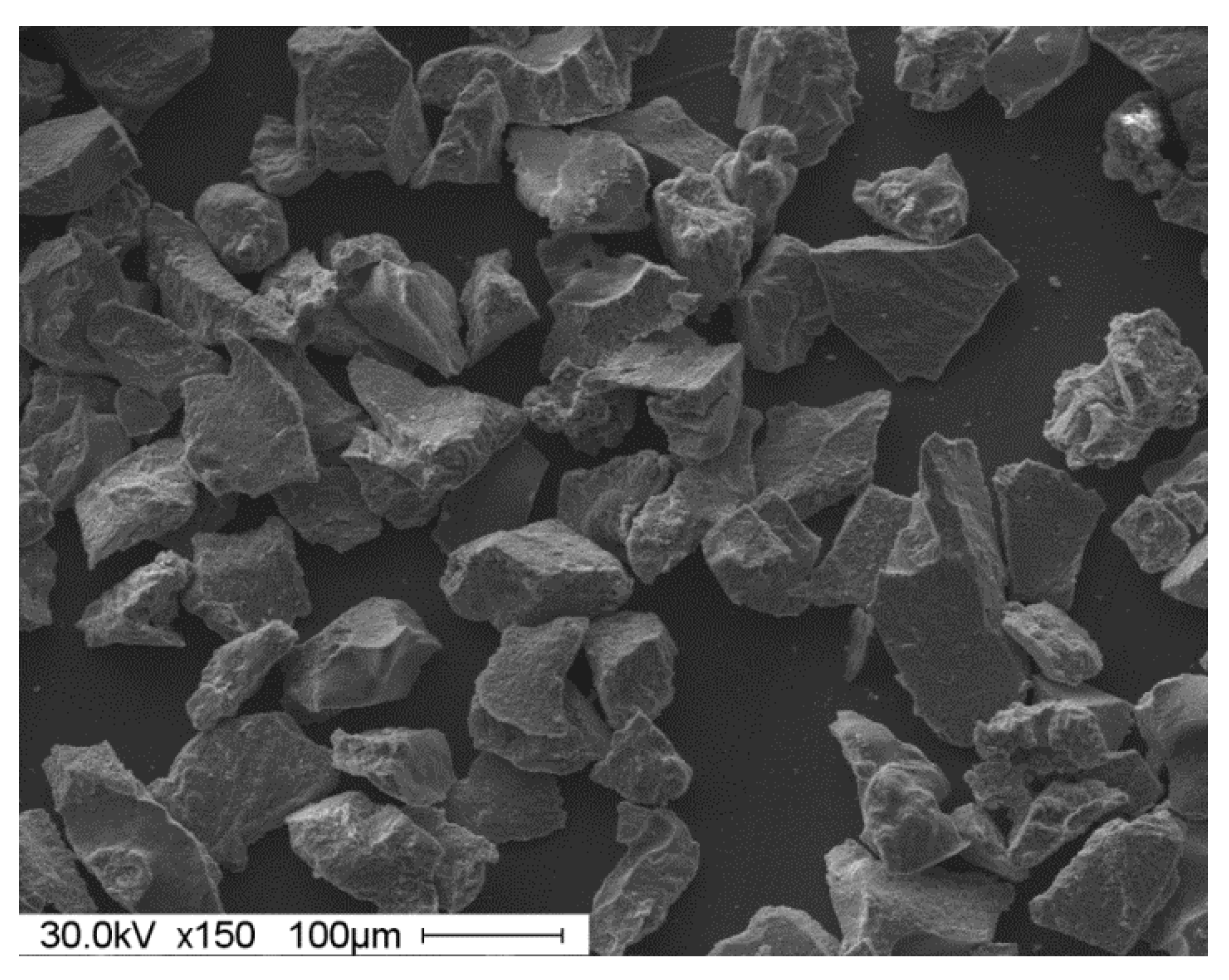
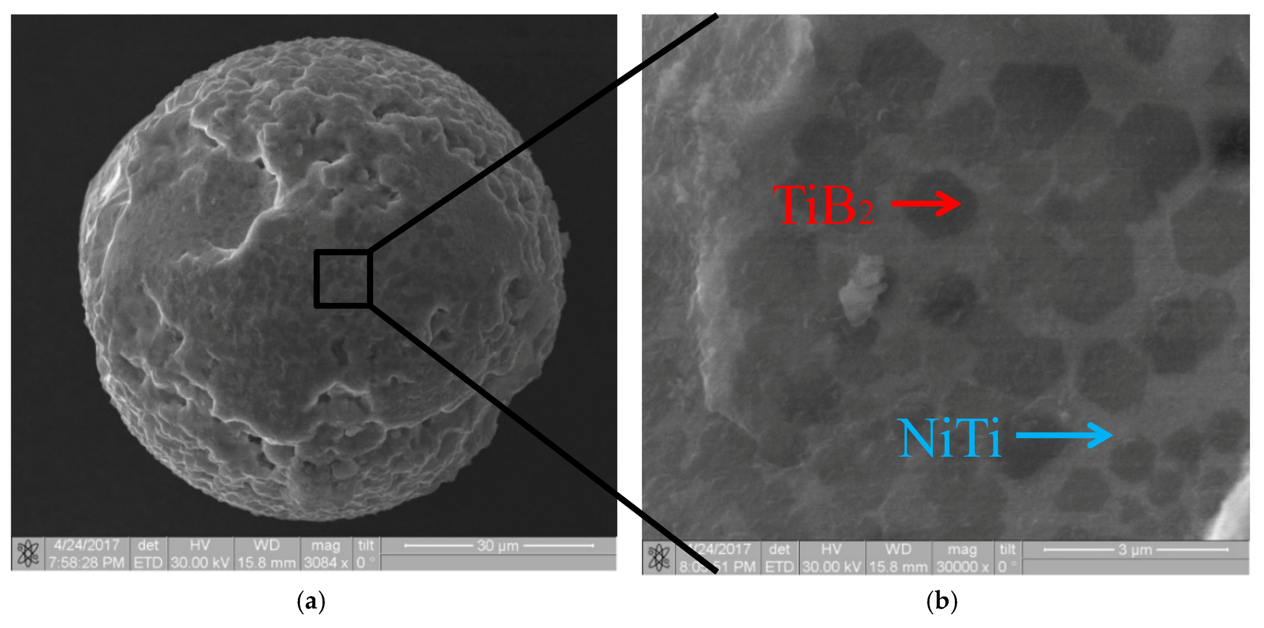
2.1. Powder Preparation

The base method for synthesizing ceramic metal composites is self-propagating high-temperature synthesis (SHS) [36]. A feature of normal SHS is the self-sustained combustion process, where the heat is generated by the direct synthesis reaction without oxygen to support combustion [37]:
A + B → AxBy + Q
where AxBy—carbides, borides, nitrides, sulfides, etc. Q is the heat of the synthesis reaction.
For the initial materials for synthesizing ceramic metal composites we used Ni powder (with the average particle size of ~5–10 µm), Ti powder (with the average particle size of ~10–20 µm), and high-purity amorphous boron powders (with the average particle size of ~500–700 nm). To remove the OH group, we dried the powders in a vacuum drying cabinet at 150 °C for 1 h. To prepare the initial mixture we mixed metal powder in the proportion of 63.5 wt% Ni-B + 36.5 wt% Ti. In order to obtain homogeneous mixtures, the powders were mixed in a planetary ball mill.
The mix was then poured into a cylindrical shaping unit made of chemical paper. The weight of a single batch was in the range of 100/500 g. After a sample had been prepared, it was placed into the reactor and vacuumized. Synthesis by combustion was performed in a laboratory SHS reactor with a volume of 12 L of inert gas (argon) atmosphere.
After SHS, the samples had the shape of cylindrical cakes. To produce powders from the SHS products, we used grinding and subsequent pulverization. At the first stage of cake pulverization, a grinder was used because the material was hard. The produced powder was sieved through a sieve with a mesh size of 3 mm. Particles over 3 mm were transported for repeat grinding until the required particle size was achieved. Powder with particle size below 3 mm was produced at the first stage of pulverization. During the second stage, the powder was pulverized to finer sizes. To produce powder of the required particle size, we ground the powder in a planetary ball mill. The powder was pulverized in steel drums with steel balls as grinders.
To obtain particles of 50–150 µm (specified by the requirements of the direct laser deposition (DLD) additive manufacturing (AM) technology) we adjusted the grinding time in order to find the optimal time for the given composition. Then, the powder was sieved through a sieve with a mesh size of 150 µm, and after it was sieved through a 50 µm sieve to obtain the required particle size. Particles over 150 µm underwent repeat grinding in the planetary ball mill.
The initial structure of the powders and the fabricated composition materials were researched using scanning electron microscopy on a 3D microscope (Quanta 200™, FEI Company, Thermo Fisher Scientific, Waltham, MA, USA). For scanning electron microscope (SEM) images, thin sample sections were prepared, a thin layer of silver was deposited on the surface of the ceramics, and then the analyses were performed. Samples were polished in a Grinder Polisher (EcoMet™ 250, Buehler, Lake Bluff, IL, USA). Vickers hardness was measured on a table-top NHT-TTX nanoindentation tester (CSM Instruments, Needham, MA, USA) at the maximum load of 100 mN, maximum indentation depth of 2100 nm, and load rate of 200 mN/min. Here, the loading time was 15 s.

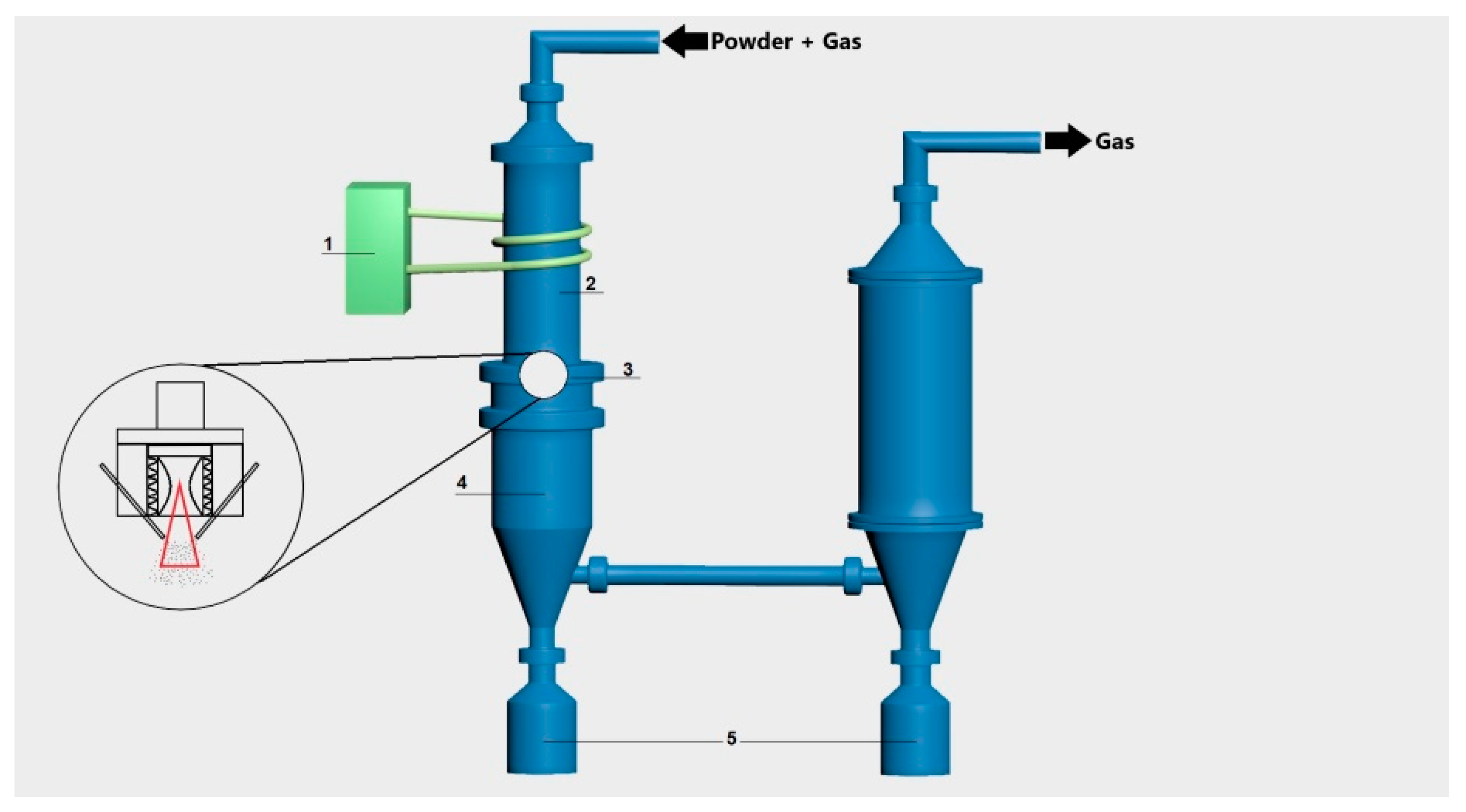
2.2. Plasma Spheroidization Technology
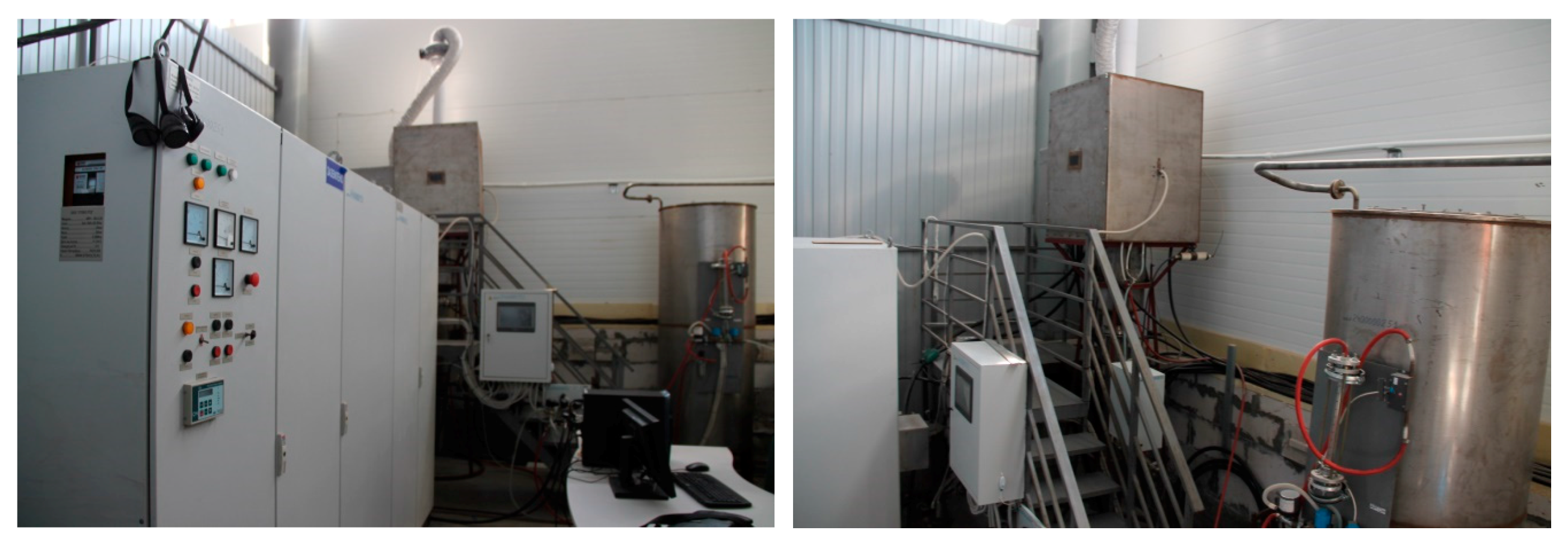
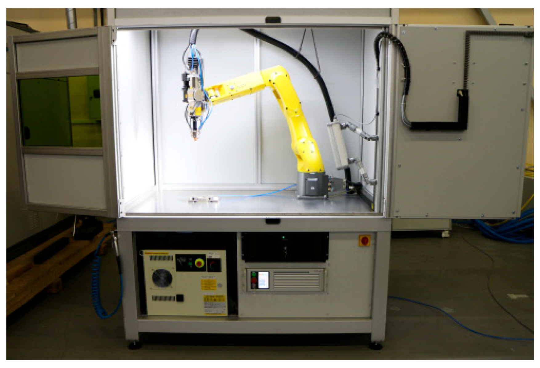
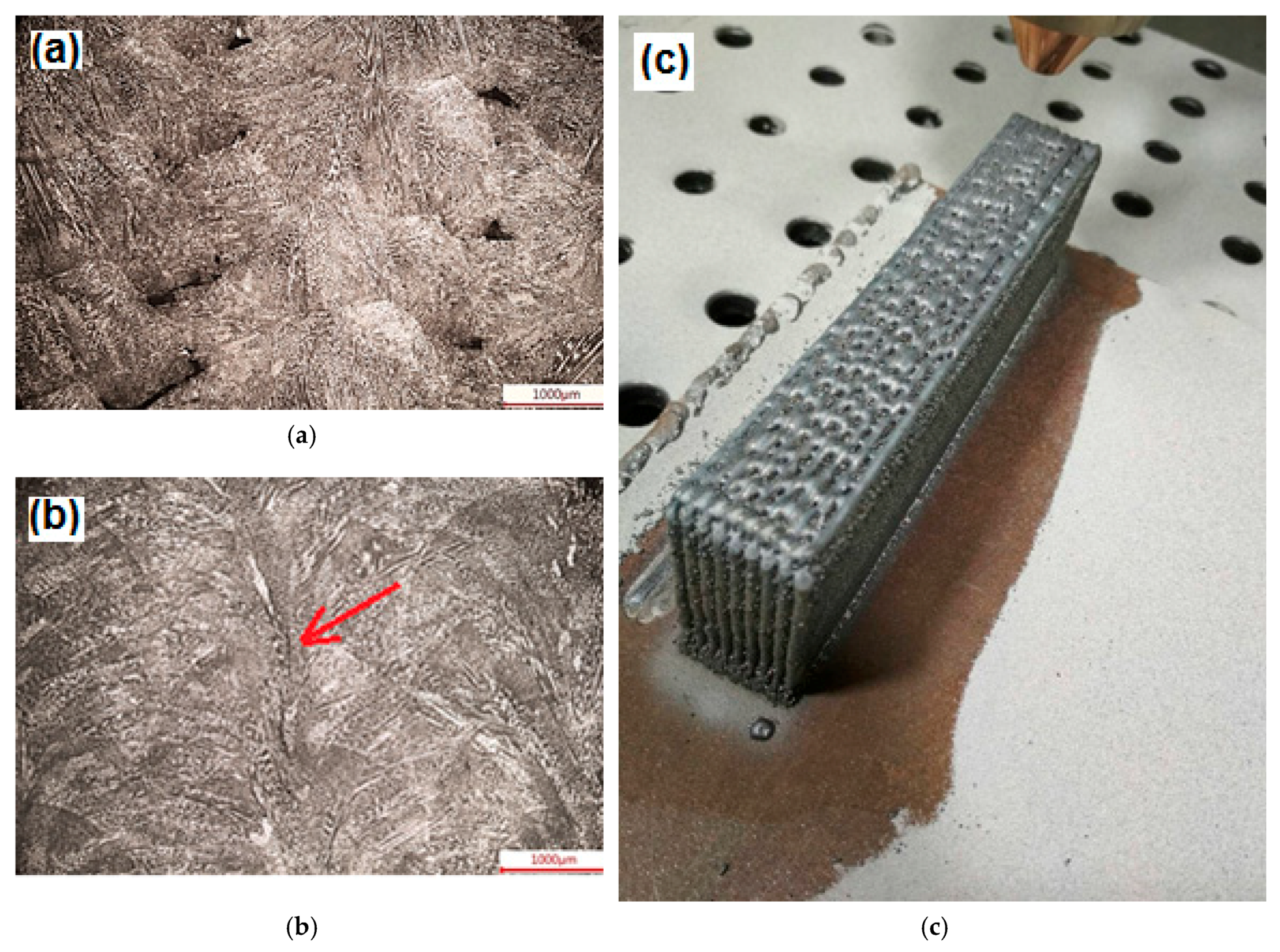
It is known that processes based on additive manufacturing technologies require spherical particle powders [38]. In this respect, plasma spheroidization of powders is one of the most efficient and best performing methods for producing quality raw materials for additive manufacturing [39]. The most forward-looking designs and facilities rely on radio-frequency gas heating. Since electrodes are not used here, plasma is extra pure (i.e., not contaminated by the products of electrodes destruction), and the low speed of the plasma jet (as compared to arc jet plasmatrons) allows particles to spend more time in the reaction zone of the jet. The plasma technology is characterized by a high heating temperature (8000 K), very fast tempering rate (100 K/s), and low contamination [39,40].
Plasma treatment was performed using the plasmatron shown in Figure 1. Under a constant flow of argon, the powders obtained after grinding in the planetary ball mill were fed into the gas jet. Particles travelling through the torch of high-temperature plasma melt and form spherical droplets because of surface tension. Then, these drops cool down and harden, thus, forming spherical particles.
In a series of research works, different researchers performed plasma treatment of hard-melting fire-resistant powders and demonstrated the efficiency of this method [41,42].
In the present research, we used plasma spheroidization to obtain spherical particle powders of ceramic metal composites of the NiTi-TiB2 system. Schematic of the plasma spheroidization facility is provided in Figure 2. With this composition, we fully matured the modes of two-stage powder preparation that included grinding in planetary ball mills and plasma spheroidization.

2.3. DLD Process

The LS-3 Yb-doped fibre laser (IRE Polus Ltd., Fryazino, Moscow Region, Russia) was used for direct laser deposition. As the source of laser radiation we used the FLW D30 laser welding head by (IPG Photonics, Oxford, UK). To form the gas powder jet, we used the COAX9 annular gap powder nozzle (Fraunhofer ILT, Aachen, Germany). The LRM-200iD_7L industrial robot (Fanuc, Oshino, Japan) was used for manipulation.
The deposited cladding layers were visually examined and instrumentally measured; then, they were investigated by optical and scanning microscopy on the DMI 500 Leica (Leica Microsystems, Wetzlar, Germany) microscopes using Thixomet (Thixomet, St.-Petersburg, Russia) and Phenom PRO X software (Thermo Fisher Scientific Phenom-World B.V., Eindhoven, The Netherlands), respectively.
A view of experimental stand is shown in Figure 3.
In the process of direct laser deposition [43], important process parameters are the shape and structure of the fabricated parts.
One of the main prerequisites for the DLD process [44] was the stability of the printed object formation process. In the implemented method, process stability was based on the principle of self-adjustment of the deposited layer heights. The process mode with good stability will sustain uniform thickness of the cladding layering and eliminate the influence of the changes in linear travel speed of the head. For example, if for some reason the Z position of the underlying layer is below or above the expected value, then the height of the next layer will be adjusted to compensate for the deviation.
The size of the laser beam spot on the substrate layer directly impacts the shape of the cross-section of the melt pool. The laser spot diameter in the laser treatment zone is adjusted by changing the distance from the laser beam focus point, thus increasing or decreasing the power density in the active zone. Hence, at constant process rate and laser output power and a small beam spot diameter, the melt pool profile will have a greater melt depth and lesser melt width. In the context of direct laser deposition, the goal was to minimize melt pool depth and extend melt pool width. Such a melt shape is optimal in terms of performance. However, as the laser spot size on the substrate surface increases, the power density decreases in proportion to the square of the spot radius. Increasing the output power of the laser adversely affects both the fabricated item and the equipment. Therefore, to ensure stable and quality fabrication, we aimed at finding a particular area of the laser beam spot that would meet the requirements regarding melt pool shape and process performance, and safety regarding process equipment failure.
By changing powder mass flow rate, we could adjust both the shape of the cladding layer and the structure of the fabricated item. For example, when the powder flow rate was increased, the height of the cladding layer also increased, thus improving process performance. However, the maximum height of the cladding layer was limited by the stability of the melt pool above the fabricated item surface.
Thus, powder flow rate impacted the geometry of the deposited layer and the structure of the fabricated item. At low flow rates, the surface of the particles was completely melted by laser radiation, forming a cast structure. At high flow rates, the surface of the particles was only partially melted, retaining the solid state of the particle cores. During the subsequent consolidation of the melt, the cores became the centres of crystallization. In this case, the fabricated item structure was fine-grained.
The process rate and deposited power parameters govern the amount of energy that is deposited into the fabricated item, thus influencing the size of the melt pool and the performance of the direct laser deposition process. By adjusting these parameters, we were able change the structure of the fabricated item. For example, at high power and low flow rate, the underlying layers may have been re-melted, which would have produced a cast structure that is characterized by dendrites that protrude through several layers. At lower power and increased flow rate, crystallization rate also increased, and a cellular-dendrite structure with cell size of up to 30 µm was formed. That is why the parameters of laser deposition are of critical importance in fabricating items from metals and composites.
As initial materials for the direct laser deposition of the sample, we used mixtures of Inconel 625 [45] and NiTi + TiB2 powders that were obtained for the purpose of this research. The amount of ceramic metal composite powders in the mixture containing Inconel 625 powders varied from 5 to 100 wt%.
To determine the optimal Direct Metal Deposition (DMD) parameters, we adjusted the following parameters: laser beam spot diameter on the substrate, laser output power, laser beam travel speed relative to the fabricated item surface, powder mass flow rate, the value of vertical and horizontal offset between layers, and deposition head passes. All parameters that were used are listed in Table 1.

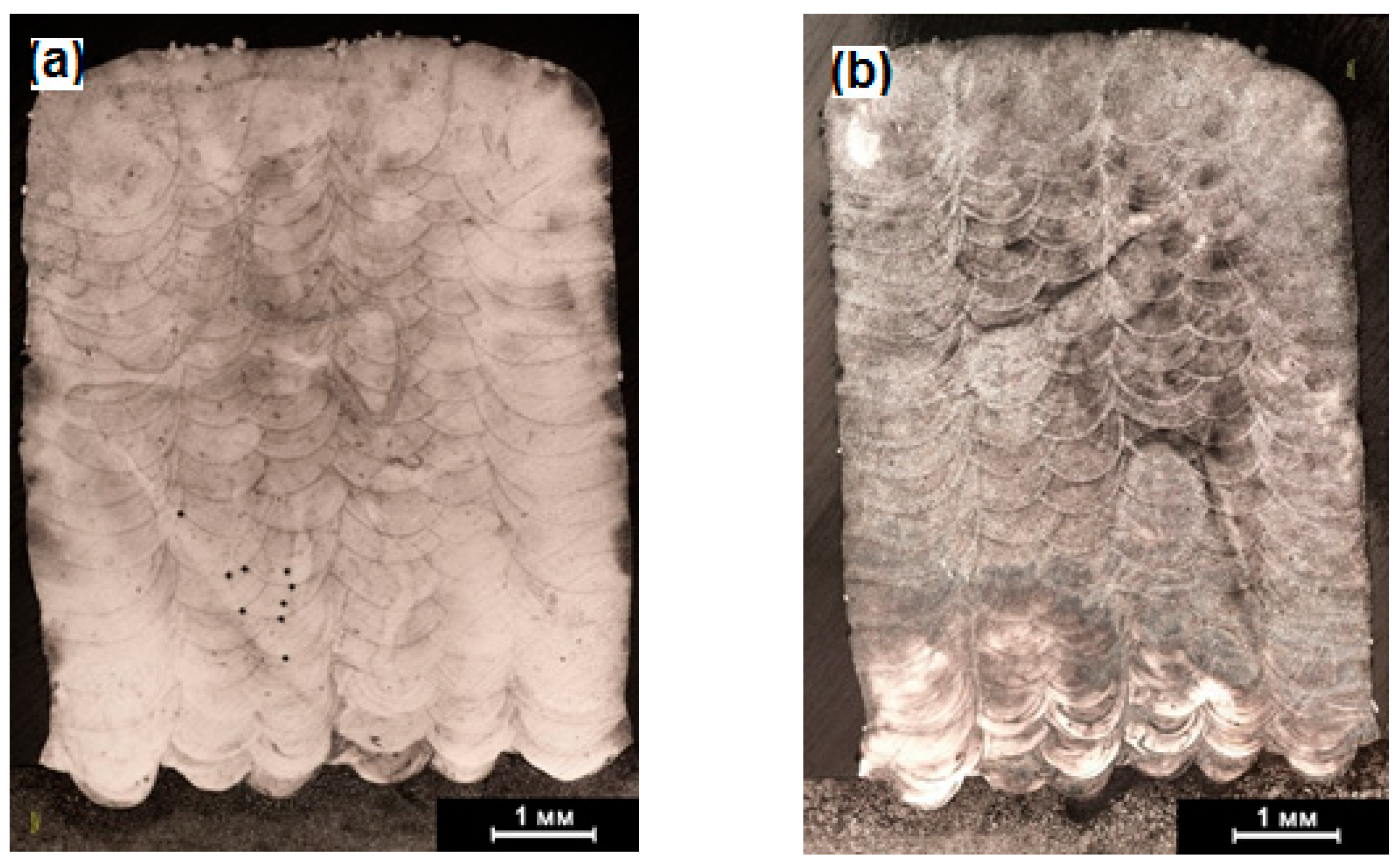
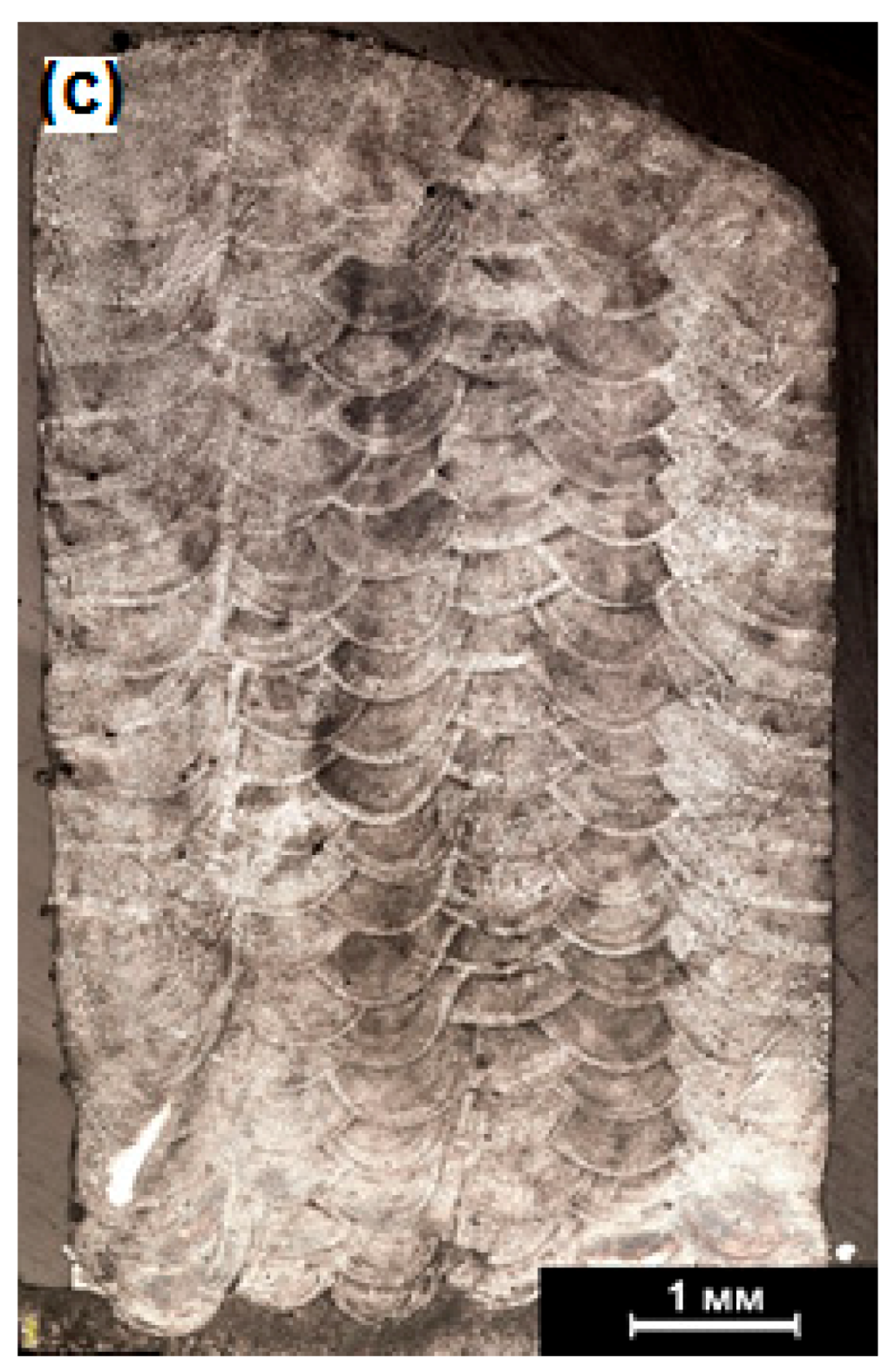
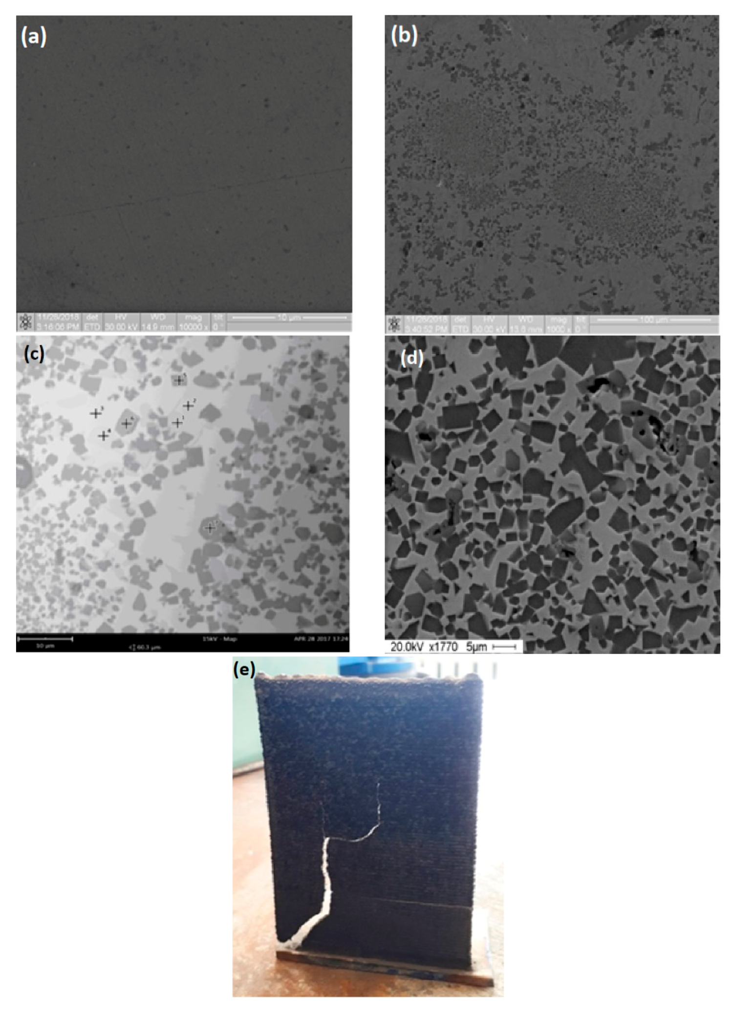
3. Results and Discussion

After synthesizing, grinding and classification, we obtained NiTi-TiB2 powders with particle sizes of 50 < <d> < 150 µm. Figure 4 shows a SEM image of the powders obtained.
It has been determined that the structure of each individual powder particle is composite (see Figure 5). The composition of the matrix is an intermetallide (NiTi) with ceramic (TiB2) microparticle inclusions (with particle sizes ranging from 0.5 to 3 µm).
According to the results of X-ray diffraction analysis, the powders contained about 70% of the ceramic phase of titanium diboride (TiB2) with an average crystallite size of 180 nm. Average crystallite size for the matrix intermetallide was 80 nm.
A schematic of the structure of each powder particle is provided in Figure 6.
The obtained NiTi-TiB2 powders have been spheroidized by high-temperature plasma treatment. The images of the structure of powder after plasma spheroidization are provided in Figure 7. Figure 7b demonstrates the retention of the composite structure of powders after plasma treatment.
The influence of laser output power on the structure of the obtained samples was researched by using the example of Inconel 625 powders. According to the research results, low laser output power leads to incomplete fusion between adjacent layers (Figure 8a), and high power leads to crack formation (Figure 8b), which leads to the unstable formation of the cladding layers (Figure 8c).
From the results of mode testing, we found that if the deposition rate for the edge layers was greatly reduced, then incomplete fusions emerged at the overlapping locations of the adjacent layers. This defect was eliminated by increasing either the laser output power or the deposition process rate. If the deposition rate was greatly increased (15 mm/s), then there was a tendency for the height of the edge layers to decrease compared to the central layers. This was because the height of the deposited layer in the layer-overlapping region was greater than the height of the layer centre. Thus, the so-called barrier emerged, and it obstructed the delivery of the powder into the treatment zone. This meant that less powder was getting into the melt pool. As the height of the sample increased, this effect kept increasing and then the edge layer formation stopped. In conclusion, we have experimentally found the ratio of powder flow rate and deposition rate that eliminates the adverse effects outlined above.
To improve process performance and material utilization, the stability of the deposition process has been researched by adjusting the powder flow rate and changing the deposition nozzle elevation step. When the powder flow rate was reduced by 2 times, the height of the deposited layer became less than the nozzle elevation steps, suggesting that the process was not stable. If the powder flow rate was reduced by 1.5 times, the process stability was maintained. Then, we increased the nozzle elevation step in order to increase performance. When the elevation step was increased, higher powder concentration was achieved in the focused jet, which resulted in an increased height of the deposited layers. However, after parameters went outside of the range of their optimal values, and as layer height increased, incomplete fusions between adjacent layers started appearing (Figure 9).
Process parameters at the power of 600 W (D = 1.5 mm, P = 600 W, V = 15 mm/s, G = 5.1 g/min) provided the lowest process performance. The shape that layers took at these parameter values allowed for making the offsets of ΔX = 1 mm and ΔZ = 0.3 mm, which gave us the performance of about 200 g/h.
To increase the performance, we tested parameters at P = 1400 W (D = 2.4 mm, P = 1400 W, V = 25 mm/s, G = 25 g/min). The shape that layers took at these parameter values allowed for making the offsets of ΔX = 1.6 mm and ΔZ = 0.8 mm, which gave us the performance of about 1100 g/h. However, when these parameters were applied to full-size industrial fabrication (i.e., the deposition process was lengthy and non-stop) rather than small-size research samples, then the focusing lens broke several times. Therefore, we also had to desist in the use of this mode.
Then, based on the regular process flow patterns that were discovered for different modes, we calculated the parameters (see Table 2) that provided for satisfactory performance (500 g/h), favorable structure, and a steady formation of the geometry of the fabricated samples.
After optimal modes of sample fabrication had been determined, we obtained ingots and walls for investigating the structure of the ceramic composites that were produced. The samples used for analyzing the structure were produced from the following mixtures: 95% Inconel 625 + 5 wt% NiTi-TiB2, 70% Inconel 625 + 30 wt% NiTi-TiB2, 50% Inconel 625 + 50 wt% NiTi-TiB2, 10% Inconel 625 + 90 wt% NiTi-TiB2, 100 wt% NiTi-TiB2.
It has been found that after the direct laser deposition of 95% Inconel 625 + 5 wt% NiTi-TiB2, inclusions of ceramics (TiB2) could be clearly discerned in the structure of the materials, with an average inclusion size of 1.3 µm (Figure 10). However, the analysis of the particle-matrix interface has shown that there are no defects at the interfaces, which may suggest good particle wettability with metal during direct laser deposition.
Increasing the content of NiTi-TiB2 in the mixture by up to 30 wt% leads to the formation of TiB2 particle clusters during the DLD process. Apparently, such cluster distribution is due to the process parameter values, at which ceramic metal composite particles do not have enough time to be properly distributed within the melt pool. However, although the deposition parameters were the same, the situation was different for the 50% Inconel 625 + 50 wt% NiTi-TiB2 composition—there were no particle clusters. It has been found that this composition was characterized by the even distribution of ceramic particles in the metal matrix. Here, the average ceramic particle size also increased by up to 3 µm. For the 10% Inconel 625 + 90 wt% NiTi-TiB2 composition, average ceramic particle size has been determined at 4.2 µm. Materials with such a structure that was obtained by direct laser deposition are characterized by high hardness, and therefore, a lesser degree of plastic deformation. To our knowledge, the first study in the literature of the deformation behavior of such materials was performed in [46]. A more detailed investigation into the physico-mechanical characteristics of the obtained materials is a topic of a separate research that we aim at conducting in the future.
We must differentiate samples produced from NiTi-TiB2 powders. As noted above, in the present study, according to the data of X-ray diffraction analysis, the content of ceramics in the intermetallide matrix was established at 70 wt%. It has been found that in the process of direct laser deposition of these samples they were destructed. Such behavior is characteristic of ceramic materials due to the peculiarities of their brittle fracture at sudden temperature changes. Thus, the threshold content of ceramic particles in the metal matrix has been determined in the present study, and at this content the DLD process can be realized at 60 wt%.
AlS10Mg alloy sample with nano TiB2 and micro TiB2 yields the best results for wear. The wear tests show that the presence of reinforcements causes a reduction of the coefficient of friction. The effect is bigger with the microsized reinforcement than with the nanosized reinforcement. This effect is probably due to the detachment from the aluminium matrix of micro- and nanoparticles of TiB2 that can act as a third body [47].

4. Conclusions

In the course of the present research, it has been found that self-propagating high-temperature synthesis can be used to produce ceramic metal composites with a metal matrix and ceramic particles with size in the range of 0.5–5 µm. The use of such ceramic metal composites is efficient in the creation of new metal matrix composites by direct laser deposition. However, a series of peculiarities in the composite structure of the materials has been discovered. The following provisions have been formulated as recommendations and further research directions.
(1)
The most promising technique lies in introducing the obtained metal matrix composites in the amount of less than 5 wt% into the metal matrix. This conclusion is based on a more even distribution of ceramic particles in the metal matrix. Apparently, several strengthening mechanisms can be simultaneously realized for such a distribution of particles; namely, dislocation and dispersion strengthening [47].
(2)
When the content of titanium diboride particles in the metal matrix is over 70 wt%, the powders cannot be used with laser deposition technologies. That is because the samples destruct, due to high internal stresses and brittle fracturing.
(3)
In the opinion of the authors of the present research, composite ceramic metal powders produced by SHS can demonstrate rather good efficiency if introduced into liquid metal, and then the melt must be atomized to obtain composite powders for additive manufacturing technologies.

Author Contributions

V.P., conceptualization, methodology, writing; A.P., M.Z., I.Z., N.S., S.K., Y.D., investigation; R.K., O.K.-K., G.T., investigation, writing; A.Z., supervision.

Funding

The research was supported by The Tomsk State University competitiveness improvement program (grant No. 8.2.2.06.2018) and was carried out with financial support from the Ministry of Education and Science of the Russian Federation (State assignment No. 11.11223.2018/11.12). The reported study was funded by RFBR according to the research project No. 18-38-00499.

Conflicts of Interest

The authors declare no conflicts of interest. The funders had no role in the design of the study; in the collection, analyses, or interpretation of data; in the writing of the manuscript, or in the decision to publish the results.

References

  1. Frazier, W.E. Metal additive manufacturing: A review. J. Mater. Eng. Perform. 2014, 23, 1917–1928. [Google Scholar] [CrossRef]
  2. Murr, L.E.; Gaytan, S.M.; Ramirez, D.A.; Martinez, E.; Hernandez, J.; Amato, K.N.; Shindo, P.W.; Medina, F.R.; Wicker, R.B. Metal fabrication by additive manufacturing using laser and electron beam melting technologies. J. Mater. Sci. Technol. 2012, 28, 1–14. [Google Scholar] [CrossRef]
  3. Sedlaka, J.; Rican, D. Study of Materials Produced by Powder Metallurgy Using Classical and Modern Additive Laser Technology. Procedia Eng. 2015, 100, 1232–1241. [Google Scholar] [CrossRef] [Green Version]
  4. Lyons, B. Additive manufacturing in aerospace: Examples and research outlook. Bridge 2014, 44, 13–19. [Google Scholar]
  5. Guo, N.; Leu, M.C. Additive manufacturing: Technology, applications and research needs. Front. Mech. Eng. 2013, 8, 215–243. [Google Scholar] [CrossRef]
  6. Mueller, B. Additive manufacturing technologies—Rapid prototyping to direct digital manufacturing. Assem. Autom. 2012, 32. [Google Scholar] [CrossRef]
  7. Uriondo, A.; Esperon-Miguez, M.; Perinpanayagam, S. The present and future of additive manufacturing in the aerospace sector: A review of important aspects. Proc. Inst. Mech. Eng. Part G J. Aerosp. Eng. 2015, 229, 2132–2147. [Google Scholar] [CrossRef]
  8. Khajavi, S.H.; Partanen, J.; Holmström, J. Additive manufacturing in the spare parts supply chain. Comput. Ind. 2014, 65, 50–63. [Google Scholar] [CrossRef]
  9. Baufeld, B.; Van der Biest, O.; Gault, R. Additive manufacturing of Ti–6Al–4V components by shaped metal deposition: Microstructure and mechanical properties. Mater. Des. 2010, 31, 106–111. [Google Scholar] [CrossRef]
  10. Jia, Q.; Gu, D. Selective laser melting additive manufacturing of Inconel 718 superalloy parts: Densification, microstructure and properties. J. Alloys Compd. 2014, 585, 713–721. [Google Scholar] [CrossRef]
  11. Lewandowski, J.J.; Seifi, M. Metal additive manufacturing: A review of mechanical properties. Annu. Rev. Mater. Res. 2016, 46, 151–186. [Google Scholar] [CrossRef]
  12. Campoli, G.; Borleffs, M.S.; Amin Yavari, S.; Wauthle, R.; Weinans, H.; Zadpoor, A.A. Mechanical properties of open-cell metallic biomaterials manufactured using additive manufacturing. Mater. Des. 2013, 49, 957–965. [Google Scholar] [CrossRef]
  13. Bertsch, A.; Jiguet, S.; Renaud, P.J. Microfabrication of ceramic components by microstereolithography. Micromech. Microeng. 2004, 14, 197–203. [Google Scholar] [CrossRef]
  14. Zocca, A.; Colombo, P.; Gomes, C.M.; Günster, J. Additive manufacturing of ceramics: Issues, potentialities, and opportunities. J. Am. Ceram. Soc. 2015, 98, 1983–2001. [Google Scholar] [CrossRef]
  15. Promakhov, V.; Zhukov, A.; Dubkova, Y.; Zhukov, I.; Kovalchuk, S.; Zhukova, T.; Olisov, O.; Klimenko, V.; Savkina, N. Structure and Properties of ZrO2–20% Al2O3 Ceramic Composites Obtained Using Additive Technologies. Materials 2018, 11, 2361. [Google Scholar] [CrossRef] [PubMed]
  16. Carroll, B.E.; Palmer, T.A.; Beese, A.M. Anisotropic tensile behavior of Ti–6Al–4V components fabricated with directed energy deposition additive manufacturing. Acta Mater. 2015, 87, 309–320. [Google Scholar] [CrossRef]
  17. Barekat, M.; Shoja Razavi, R.; Ghasemi, A. Nd: YAG laser cladding of Co–Cr–Mo alloy on γ-TiAl substrate. Opt. Laser Technol. 2016, 80, 145–152. [Google Scholar] [CrossRef]
  18. Moussaoui, K.; Rubio, W.; Mousseigne, M.; Sultan, T.; Rezai, F. Effects of Selective Laser Melting additive manufacturing parameters of Inconel 718 on porosity, microstructure and mechanical properties. Mater. Sci. Eng. A 2018, 735, 182–190. [Google Scholar] [CrossRef]
  19. Weng, Z.; Wang, A.; Wang, Y.; Xiong, D.; Tang, H. Diode laser cladding of Fe-based alloy on ductile cast iron and related interfacial behavior. Surf. Coat. Technol. 2016, 286, 64–71. [Google Scholar] [CrossRef]
  20. Hashim, J.; Looney, L.; Hashmi, M.S.J. Metal matrix composites: Production by the stir casting method. J. Mater. Process. Technol. 1999, 92, 1–7. [Google Scholar] [CrossRef]
  21. Tjong, S.C. Novel nanoparticle-reinforced metal matrix composites with enhanced mechanical properties. Adv. Eng. Mater. 2007, 9, 639–652. [Google Scholar] [CrossRef]
  22. Vorozhtsov, S.A.; Eskin, D.G.; Tamayo, J.; Vorozhtsov, A.B.; Promakhov, V.V.; Averin, A.A.; Khrustalyov, A.P. The Application of External Fields to the Manufacturing of Novel Dense Composite Master Alloys and Aluminum-Based Nanocomposites. Metall. Mater. Trans. A 2015, 46, 2870–2875. [Google Scholar] [CrossRef] [Green Version]
  23. Rawal, S.P. Metal-matrix composites for space applications. JOM 2001, 53, 14–17. [Google Scholar] [CrossRef]
  24. Alba-Baena, N.; Eskin, D. Kinetics of ultrasonic degassing of aluminum alloys. In Light Metals 2013; Minerals, Metals and Materials Series; Springer: Cham, Switzerland, 2016; pp. 957–962. [Google Scholar]
  25. Grandfield, J.; Eskin, D.G.; Bainbridge, I. Direct-Chill Casting of Light Alloys: Science and Technology; John Wiley & Sons: Hoboken, NJ, USA, 2013. [Google Scholar]
  26. Vorozhtsov, S.; Zhukov, I.; Promakhov, V.; Naydenkin, E.; Khrustalyov, A.; Vorozhtsov, A. The Influence of ScF3 Nanoparticles on the Physical and Mechanical Properties of New Metal Matrix Composites Based on A356 Aluminum Alloy. JOM 2016, 68, 3101–3106. [Google Scholar] [CrossRef]
  27. Martin, J.H.; Yahata, B.D.; Hundley, J.M.; Mayer, J.A.; Schaedler, T.A.; Pollock, T.M. 3D printing of high-strength aluminium alloys. Nature 2017, 549, 365. [Google Scholar] [CrossRef]
  28. Zhang, B.; Bi, G.; Nai, S.; Sun, C.N.; Wei, J. Microhardness and microsructure evolution of TiB2 reinficed Inconel 625/TiB2 composite produced by selective laser melting. Opt. Laser Technol. 2016, 80, 186–195. [Google Scholar] [CrossRef]
  29. Vorozhtsov, S.; Zhukov, I.; Vorozhtsov, A.; Zhukov, A.; Eskin, D.; Kvetinskaya, A. Synthesis of micro-and nanoparticles of metal oxides and their application for reinforcement of Al-based alloys. Adv. Mater. Sci. Eng. 2015, 2015, 718207. [Google Scholar] [CrossRef]
  30. Nikhilesh, C.; Shen, Y.-L. Mechanical behavior of particle reinforced metal matrix composites. Adv. Eng. Mater. 2001, 3, 357–370. [Google Scholar]
  31. Casati, R.; Vedani, M. Metal matrix composites reinforced by nano-particles—A review. Metals 2014, 4, 65–83. [Google Scholar] [CrossRef]
  32. Tong, J.B.; Lu, X.; Liu, C.C.; Wang, L.N.; Qu, X.H. Compact Process for the Preparation of Microfine Spherical High-Niobium-Containing TiAl Alloy Powders. JOM 2015, 67, 573–579. [Google Scholar] [CrossRef]
  33. Schmidt, J.; Boehling, M.; Burkhardt, U.; Grin, Y. Preparation of titanium diboride TiB2 by spark plasma sintering at slow heating rate. Sci. Technol. Adv. Mater. 2007, 8, 376–382. [Google Scholar] [CrossRef]
  34. Schmidt, J.; Boehling, M.; Burkhardt, U.; Grin, Y. Micromechanism in self-lubrication of TiB2/Al composite. ACS Appl. Mater. Interfaces 2015, 7, 12688–12694. [Google Scholar]
  35. Basu, B.; Raju, G.B.; Suri, A.K. Processing and properties of monolithic TiB2 based materials. Int. Mater. Rev. 2016, 51, 352–374. [Google Scholar] [CrossRef]
  36. Merzhanov, A.G. Self-propagating high-temperature synthesis: Twenty years of search and findings. Combust. Plasma Synth. High-Temp. Mater. 1990, 225, 83–90. [Google Scholar]
  37. Yi, H.C.; Moore, J.J. Self-propagating high-temperature (combustion) synthesis (SHS) of powder-compacted materials. J. Mater. Sci. 1990, 25, 1159–1168. [Google Scholar] [CrossRef]
  38. King, W.E. Laser powder bed fusion additive manufacturing of metals; physics, computational, and materials challenges. Appl. Phys. Rev. 2015, 2, 041304. [Google Scholar] [CrossRef] [Green Version]
  39. Shanmugavelayutham, G.; Selvarajan, V. Plasma spheroidization of nickel powders in a plasma reactor. Bull. Mater. Sci. 2004, 27, 453–457. [Google Scholar] [CrossRef] [Green Version]
  40. Gomez, E.; Rani, D.A.; Cheeseman, C.R.; Deegan, D.; Wise, M.; Boccaccin, A.R. Thermal plasma technology for the treatment of wastes: A critical review. J. Hazard. Mater. 2009, 161, 614–626. [Google Scholar] [CrossRef] [PubMed]
  41. Károly, Z.; Szépvölgyi, J. Plasma spheroidization of ceramic particles. Chem. Eng. Process. Process Intensif. 2015, 44, 221–224. [Google Scholar] [CrossRef]
  42. Chaturvedi, V.; Ananthapadmanabhan, P.V.; Chakravarthy, Y.; Bhandari, S.; Tiwari, N.; Pragatheeswaran, A.; Das, A.K. Thermal plasma spheroidization of aluminum oxide and characterization of the spheroidized alumina powder. Ceram. Int. 2014, 40, 8273–8279. [Google Scholar] [CrossRef]
  43. Turichin, G.A.; Klimova, O.G.; Zemlyakov, E.V.; Babkin, K.D.; Kolodyazhnyy, D.Y.; Shamray, F.A.; Travyanov, A.Y.; Petrovskiy, P.V. Technological aspects of high speed direct laser deposition based on heterophase powder metallurgy. Phys. Procedia 2015, 78, 397–406. [Google Scholar] [CrossRef]
  44. Turichin, G.A.; Somonov, V.V.; Klimova, O.G. Investigation and modeling of the process of formation of the pad weld and its microstructure during laser cladding by radiation of high power fiber laser. Appl. Mech. Mater. 2014, 682, 160–165. [Google Scholar] [CrossRef]
  45. Dinda, G.P.; Dasgupta, A.K.; Mazumder, J. Laser aided direct metal deposition of Inconel 625 superalloy: Microstructural evolution and thermal stability. Mater. Sci. Eng. A 2009, 509, 98–104. [Google Scholar] [CrossRef]
  46. Bakeev, R.A.; Makarov, P.V.; Pereskin, A.Y.; Promakhov, V.V.; Zhukov, A.S.; Klimova-Korsmik, O.G. Experimental and numerical study of the mechanical properties and features of the deformation and destruction of the metal-ceramic composite TiNi–TiB2, obtained by direct laser growth. Phys. Mesomech. 2018, 21, 56–66. [Google Scholar]
  47. Lorusso, M.; Aversa, A.; Manfredi, D.; Calignano, F.; Ambrosio, E.P.; Ugues, D.; Pavese, M. Tribological behavior of aluminum alloy AlSi10Mg-TiB2 composites produced by direct metal laser sintering (DMLS). J. Mater. Eng. Perform. 2016, 25, 3152–3190. [Google Scholar] [CrossRef]
Figure 1. Facility for the plasma spheroidization of powders.
Metals 09 00141 g001
Figure 2. Schematic of the plasma spheroidization facility. (1) High frequency generator, (2) plasmatron, (3) nozzle, (4) reactor, (5) powder collection containers.
Metals 09 00141 g002
Figure 3. A view of experimental stand.
Metals 09 00141 g003
Figure 4. Image of NiTi-TiB2 powder.
Metals 09 00141 g004
Figure 5. Composition structure of NiTi-TiB2 powders obtained by using SHS technology.
Metals 09 00141 g005
Figure 6. Schematic of the structure of NiTi-TiB2 powders obtained by using SHS technology.
Metals 09 00141 g006
Figure 7. Structure of ceramic metal composite NiTi-TiB2 powders after plasma spheroidization: (a) particle image in powder system NiTi-TiB2 and (b) image of the microstructure of the powder particle system NiTi-TiB2.
Metals 09 00141 g007
Figure 8. Defects in the structure of the samples that emerge because of incorrectly selected process parameters. (a) Incomplete fusions, (b) cracks, and (c) unstable formation of the cladding layers caused by a breakage of the focusing lens.
Metals 09 00141 g008
Figure 9. Macrostructure of the samples obtained by adjusting the elevation step. (a) Elevation step at 0.2 mm, (b) elevation step at 0.3 mm, and (c) elevation step at 0.35 mm.
Metals 09 00141 g009aMetals 09 00141 g009b
Figure 10. Structure of the produced metal matrix composites: (a) Inconel 625 + 5% NiTi-TiB2; (b) Inconel 625 + 30% NiTi-TiB2; (c) Inconel 625 + 50%NiTi-TiB2; (d) Inconel 625 + 90%NiTi-TiB2; (e) 100% NiTi-TiB2.
Metals 09 00141 g010
Table 1. Modes used to determine the optimal Direct Metal Deposition (DMD) parameters.
Laser Beam Diameter in the Treatment Zone, mm (D)Power, W (P)Edge Layers Deposition Rate, mm/s (Vk)Intermittent Layers Deposition Rate, mm/s (Vz)Powder Flow Rate, g/min (G)X Offset, mm (ΔX)Z Offset, mm (ΔZ)
1.5–2.4500–140010–1515–255.1–250.7–1.60.2–0.8
Table 2. Process parameters for the fabrication of samples.
Laser Beam Diameter in the Treatment Zone, mm (D)Power, W (P)Edge Layers Claddingrate, mm/s (Vk)Intermittent Layers Claddingrate, mm/s (Vz)Powder Flow Rate, g/min (G)X Offset, mm (ΔX)Z Offset, mm (ΔZ)
2.110001525231.40.6

