Microstructural Evolution and Short-Term Creep Rupture of the Simulated HAZ in T92 Steel Normalized at Different Temperatures


Abstract
1. Introduction
2. Materials and Experimental Procedures
3. Results
4. Discussion
5. Conclusions
- (1)
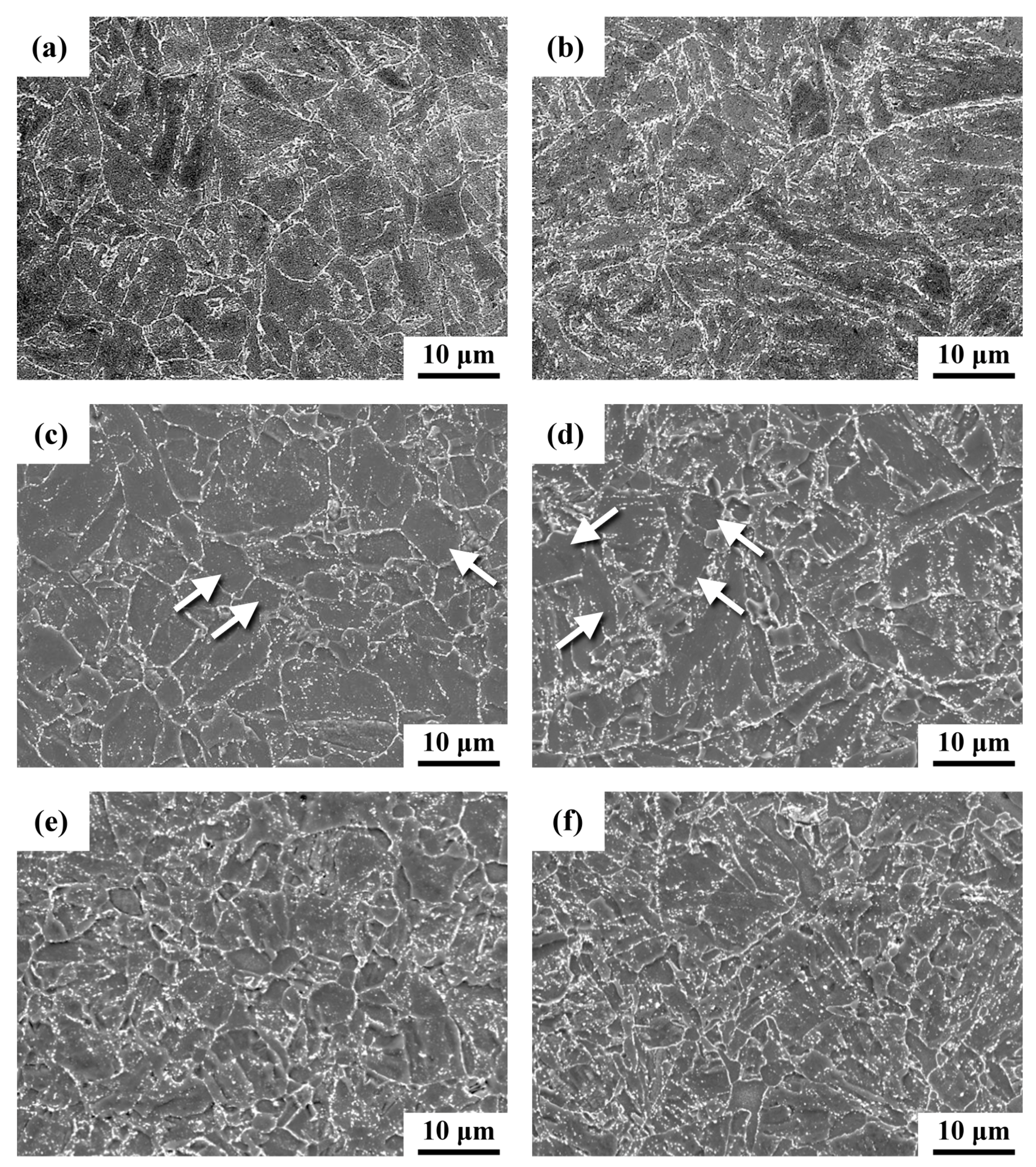
- Increasing the normalizing temperature of T92 steel tube from 1213 K to 1333 K led to the formation of finer carbides but in greater numbers in the sample after tempering at 1033 K for 2 h.
- (2)
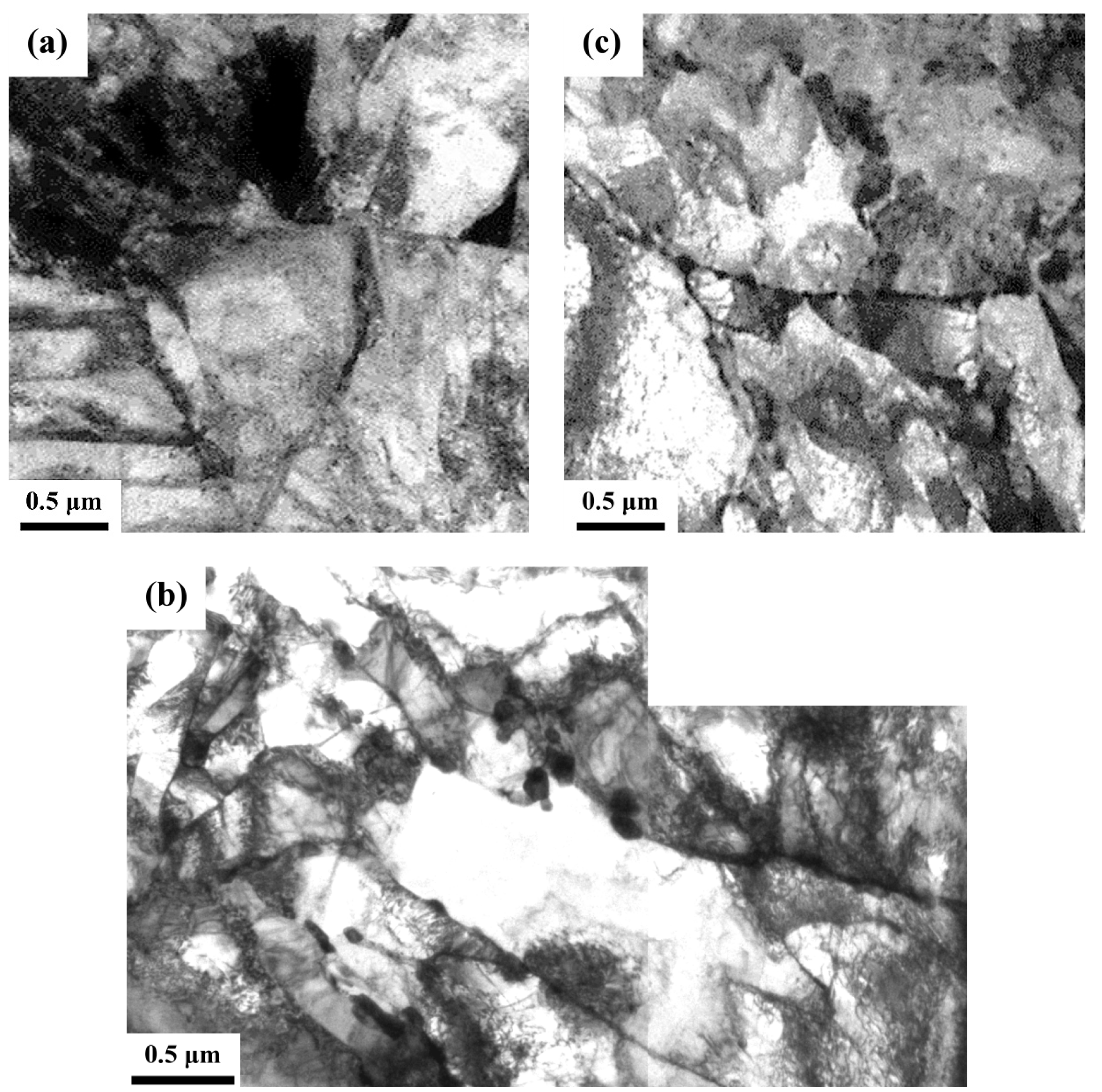
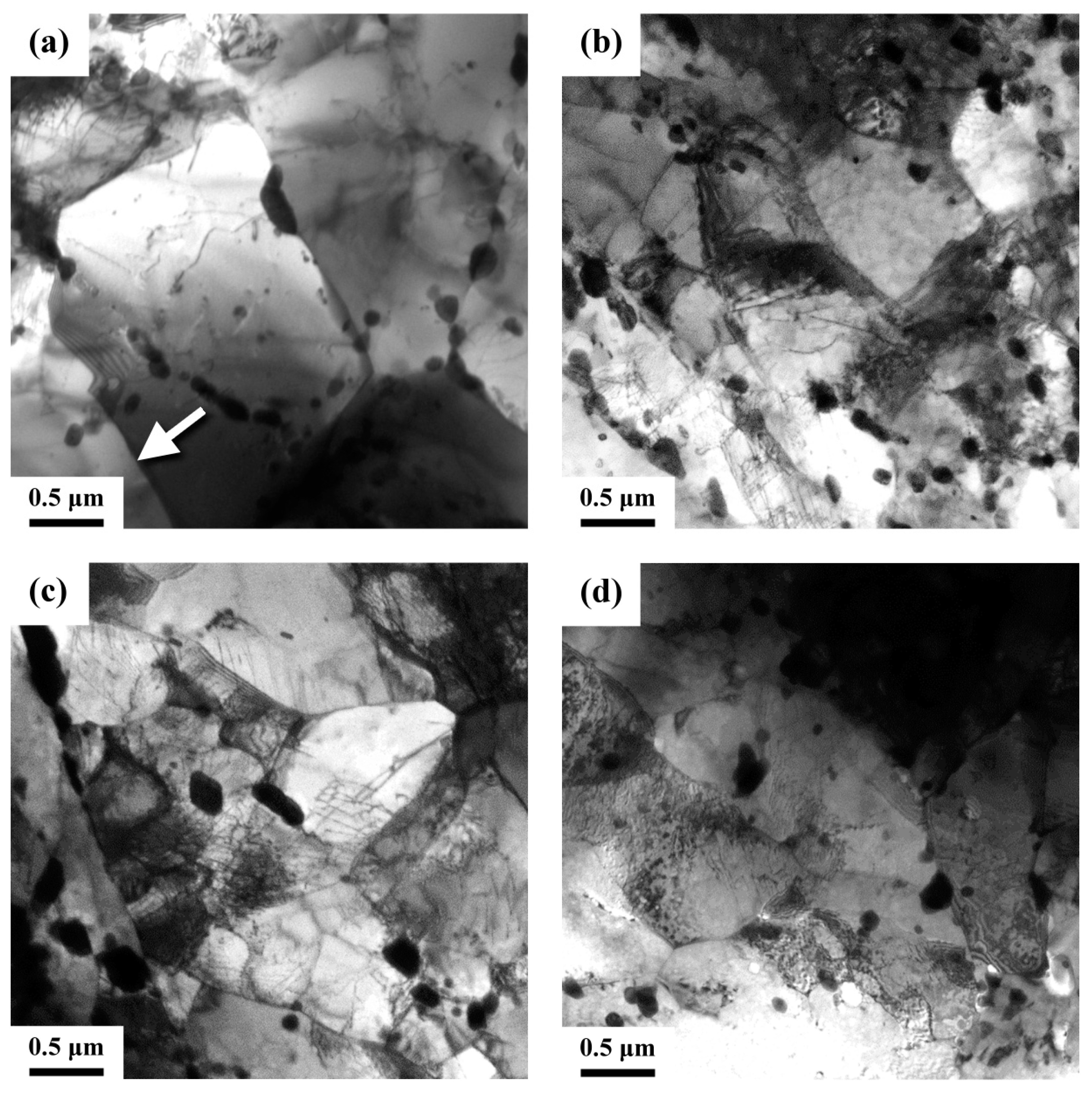
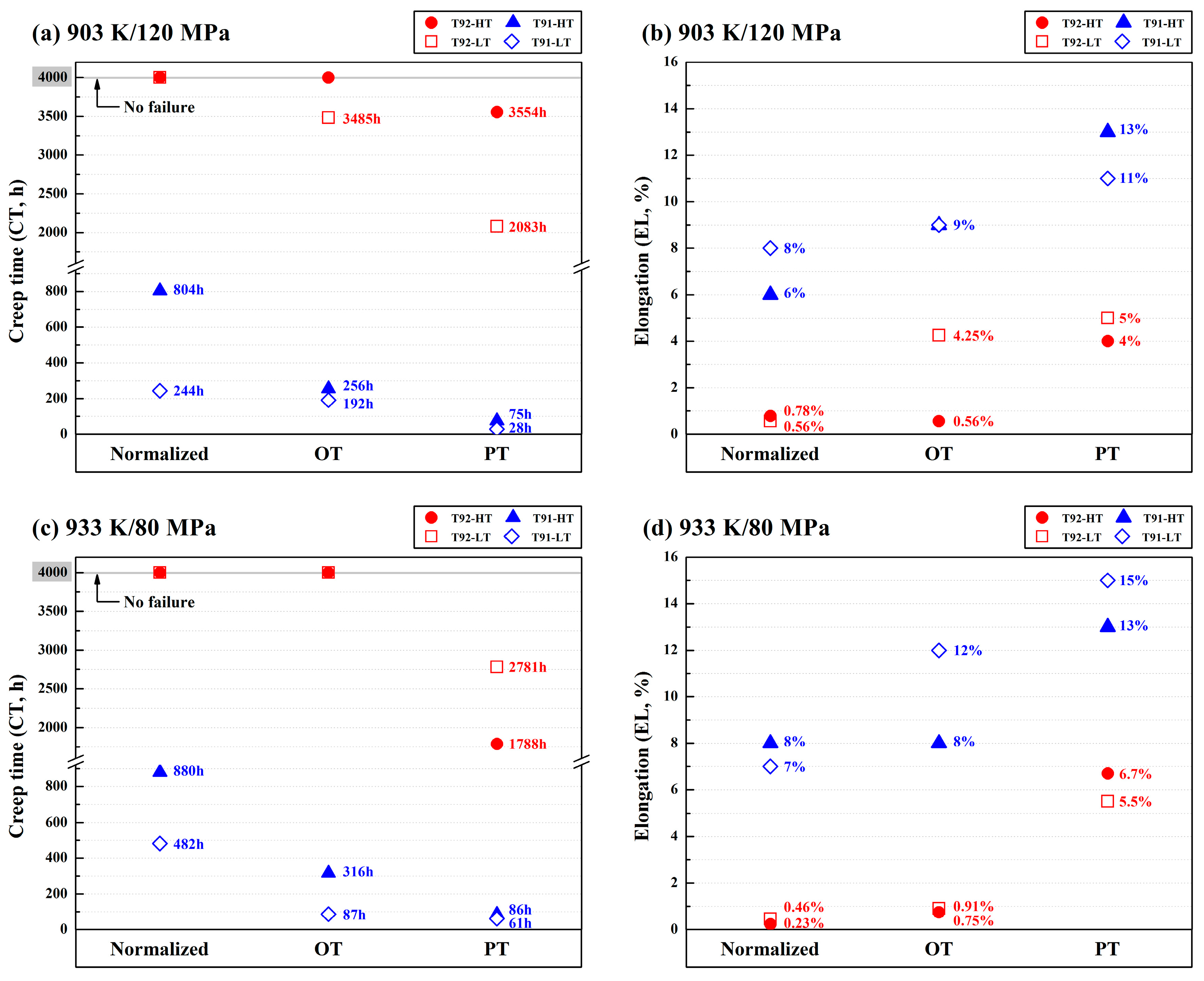
- Dislocation recovery, polygonization, and carbide-coarsening occurred in the over-tempered (OT) samples, leading to a decline in hardness relative to those of the normalized and tempered substrates. The formation of soft zones or ferrite subgrains in the OT samples played an important role in degrading their creep resistance, as compared with the LT and HT samples.
- (3)
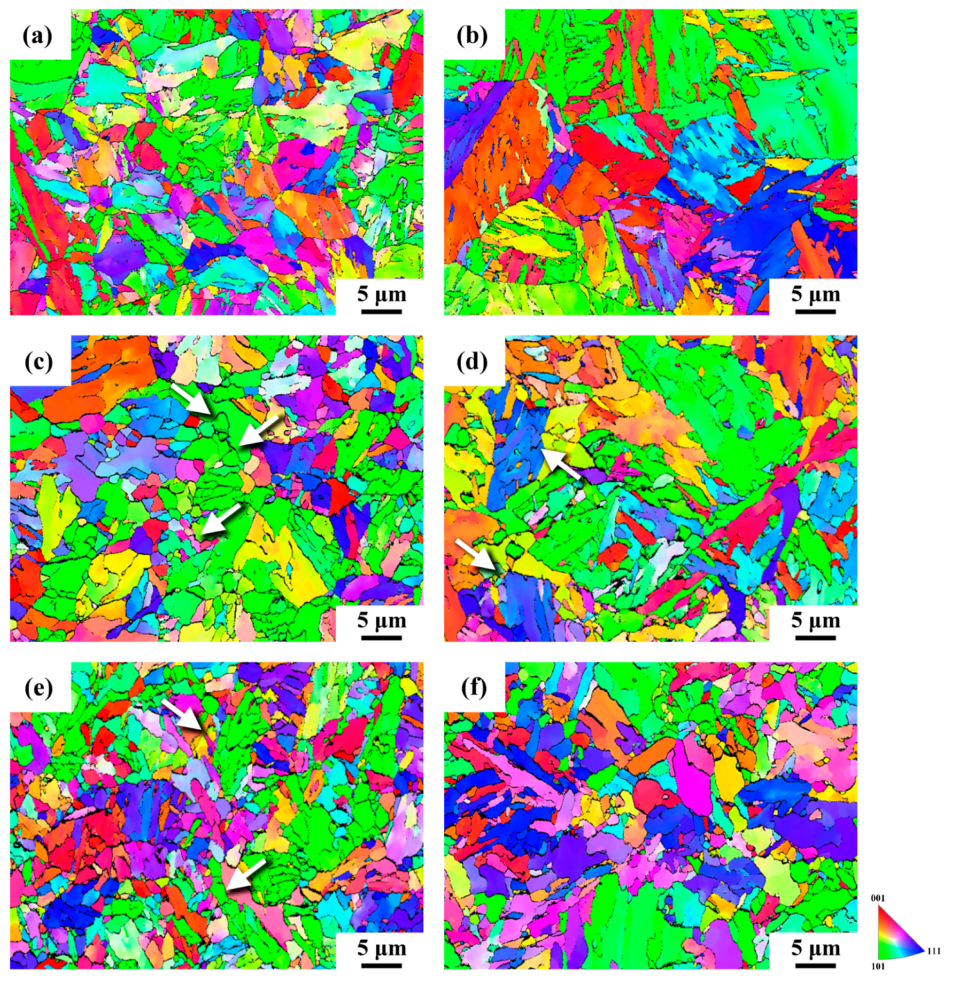
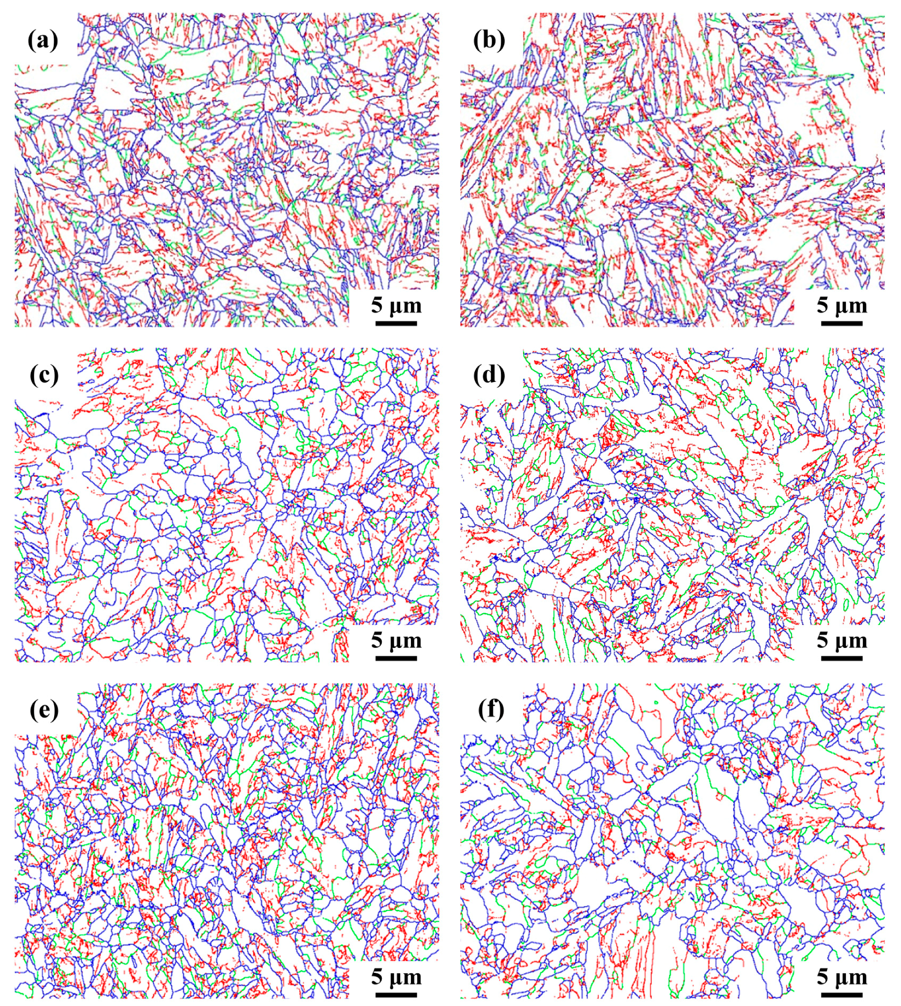
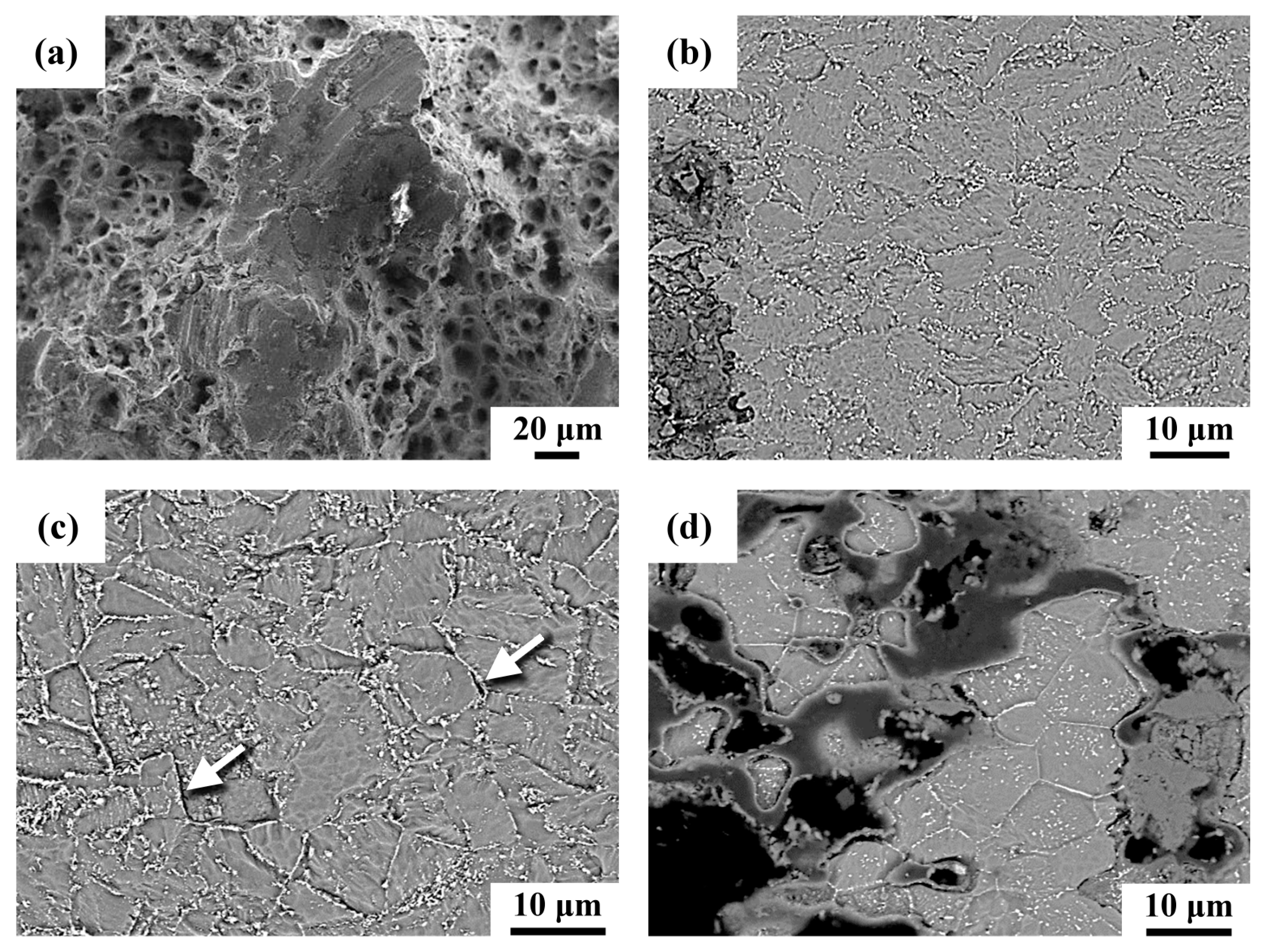
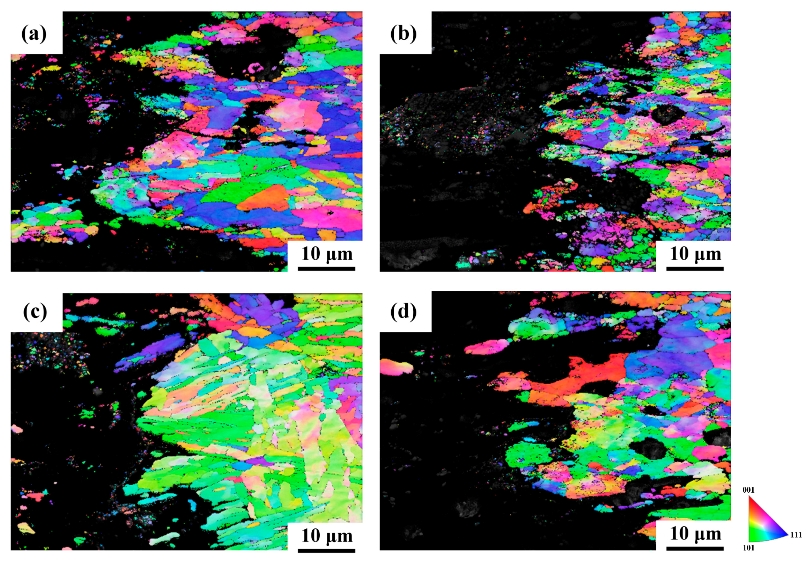
- The PT samples, especially the LT-PT one, comprised fine-grained structures. All the creep cracks were found to nucleate mainly at the high-angle grain boundaries; thus, the fine-grained structure had an obviously adverse effect on its creep resistance. Coarse carbides along the grain and subgrain boundaries and the presence of ferrite soft zones accounted for the inferior creep resistance of the PT samples.
- (4)
- The microstructures of the T92 steel tube were more stable and resistant to degradation than those of the Gr.91 steel, if welding thermal cycles or loading at elevated temperatures were applied. Such events were responsible for the better creep resistance of the simulated T92 samples than that of the simulated Gr.91 ones under the same creep-rupture conditions.
Author Contributions
Funding
Conflicts of Interest
References
- Viswanathan, R.; Bakker, W.T. Materials for boilers in ultra supercritical power plants. In Proceedings of the International Joint Power Generation Conference, Miami Beach, FL, USA, 23–26 July 2000. [Google Scholar]
- Brózda, J. New generation creep-resistant steels, their weldability and properties of welded joints: T/P92 steel. Weld. Int. 2005, 19, 5–13. [Google Scholar] [CrossRef]
- Caminada, S.; Cumino, G.; Lauro, A. Experiences in the use of advanced materials for Ultra Super Critical thermoelectric power plants: ASTM P92 grade and its weldability. Weld. Int. 2012, 26, 910–920. [Google Scholar] [CrossRef]
- Horiuchi, T.; Igarashi, M.; Abe, F. Improved utilization of added B in 9Cr heat-resistant steels containing W. ISIJ Int. 2002, 42, S67–S71. [Google Scholar] [CrossRef]
- Albert, S.K.; Kondo, M.; Tabuchi, M.; Yin, F.; Sawada, K.; Abe, F. Improving the creep properties of 9Cr-3W-3Co-NbV steels and their weld joints by the addition of boron. Metall. Mater. Trans. A 2005, 36, 333–343. [Google Scholar] [CrossRef]
- Das, C.R.; Albert, S.K.; Swaminathan, J.; Raju, S.; Bhaduri, A.K.; Murty, B.S. Transition of crack from Type IV to Type II resulting from improved utilization of Boron in the modified 9Cr-1Mo steel weldment. Metall. Mater. Trans. A 2012, 43, 3724–3741. [Google Scholar] [CrossRef]
- Abe, F.; Tabuchi, M.; Tsukamoto, S.; Shirane, T. Microstructure evolution in HAZ and suppression of Type IV fracture in advanced ferritic power plant steels. Int. J. Press. Vessel. Pip. 2010, 87, 598–604. [Google Scholar] [CrossRef]
- Hong, S.G.; Lee, W.B.; Park, C.G. The effects of tungsten addition on the microstructural stability of 9Cr–Mo Steels. J. Nucl. Mater. 2001, 288, 202–207. [Google Scholar] [CrossRef]
- Chilukuru, H.; Durst, K.; Wadekar, S.; Schwienheer, M.; Scholz, A.; Berger, C.; Mayer, K.H.; Blum, W. Coarsening of precipitates and degradation of creep resistance in tempered martensite steels. Mater. Sci. Eng. A 2009, 510–511, 81–87. [Google Scholar] [CrossRef]
- Abe, F. Coarsening behavior of lath and its effect on creep rates in tempered martensitic 9Cr–W steels. Mater. Sci. Eng. A 2004, 387, 565–569. [Google Scholar] [CrossRef]
- Otoguro, Y.; Matsubara, M.; Itoh, I.; Nakazawa, T. Creep rupture strength of heat affected zone for 9Cr ferritic heat resisting steels. Nucl. Eng. Des. 2000, 196, 51–61. [Google Scholar] [CrossRef]
- Li, Y.; Monma, Y.; Hongo, H.; Tabuchi, M. Evaluation of creep damage in a welded joint of modified 9Cr–1Mo steel. J. Nucl. Mater. 2010, 405, 44–49. [Google Scholar] [CrossRef]
- Gaffard, V.; Gourgues-Lorenzon, A.F.; Besson, J. High temperature creep flow and damage properties of the weakest area of 9Cr1Mo-NbV martensitic steel weldments. ISIJ Int. 2005, 45, 1915–1924. [Google Scholar] [CrossRef]
- Das, C.R.; Albert, S.K.; Bhaduri, A.K.; Srinivasan, G.; Murty, B.S. Effect of prior microstructure on microstructure and mechanical properties of modified 9Cr–1Mo steel weld joints. Mater. Sci. Eng. A 2008, 477, 185–192. [Google Scholar] [CrossRef]
- Divya, M.; Das, C.R.; Albert, S.K.; Goyal, S.; Ganesh, P.; Kaul, R.; Swaminathan, J.; Murty, B.S.; Kukreja, L.M.; Bhaduri, A.K. Influence of welding process on Type IV cracking behavior of P91 steel. Mater. Sci. Eng. A 2014, 613, 148–158. [Google Scholar] [CrossRef]
- Wang, Y.; Li, L.; Kannan, R. Transition from Type IV to Type I cracking in heat-treated grade 91 steel weldments. Mater. Sci. Eng. A 2018, 714, 1–13. [Google Scholar] [CrossRef]
- Albert, S.K.; Matsui, M.; Watanabe, T.; Hongo, H.; Kubo, K.; Tabuchi, M. Variation in the Type IV cracking behaviour of a high Cr steel weld with post weld heat treatment. Int. J. Press. Vessel. Pip. 2003, 80, 405–413. [Google Scholar] [CrossRef]
- Hongo, H.; Tabuchi, M.; Watanabe, T. Type IV creep damage behavior in Gr. 91 steel welded joints. Metall. Mater. Trans. A 2012, 43, 1163–1173. [Google Scholar] [CrossRef]
- Xue, W.; Pan, Q.G.; Ren, Y.Y.; Shang, W.; Zeng, H.Q.; Liu, H. Microstructure and type IV cracking behavior of HAZ in P92 steel weldment. Mater. Sci. Eng. A 2012, 552, 493–501. [Google Scholar] [CrossRef]
- Liu, Y.; Tsukamoto, S.; Shirane, T.; Abe, F. Formation mechanism of type IV failure in high Cr ferritic heat-resistant steel-welded joint. Metall. Mater. Trans. A 2013, 44, 4626–4633. [Google Scholar] [CrossRef]
- Velkavrh, I.; Kafexhiu, F.; Klien, S.; Diem, A.; Podgornik, B. Tempering-Induced Microstructural Changes in the Weld Heat-Affected Zone of 9 to 12 Pct Cr Steels and Their Influence on Sliding Wear. Metall. Mater. Trans. A 2017, 48, 109–125. [Google Scholar] [CrossRef]
- Milović, L.; Vuherer, T.; Blačić, I.; Vrhovac, M.; Stanković, M. Microstructures and mechanical properties of creep resistant steel for application at elevated temperatures. Mater. Des. 2013, 46, 660–667. [Google Scholar] [CrossRef]
- Xu, X.; West, G.D.; Siefert, J.A.; Parker, J.D.; Thomson, R.C. The influence of thermal cycles on the microstructure of grade 92 steel. Metall. Mater. Trans. A 2017, 48, 5396–5414. [Google Scholar] [CrossRef]
- Hsiao, T.H.; Chen, T.C.; Jeng, S.L.; Chung, T.J.; Tsay, L.W. Effects of simulated microstructure on the creep rupture of the modified 9Cr-1Mo steel. J. Mater. Eng. Perform. 2016, 25, 4317–4325. [Google Scholar] [CrossRef]
- Tabuchi, M.; Watanabe, T.; Kubo, K.; Matsui, M.; Kinugawa, J.; Abe, F. Creep crack growth behavior in the HAZ of weldments of W containing high Cr steel. Int. J. Press. Vessel. Pip. 2001, 78, 779–784. [Google Scholar] [CrossRef]
- Abe, F.; Tabuchi, M. Microstructure and creep strength of welds in advanced ferritic power plant steels. Sci. Technol. Weld. Join. 2004, 9, 22–30. [Google Scholar] [CrossRef]
- Pandey, C.; Giri, A.; Mahapatra, M.M. Effect of normalizing temperature on microstructural stability and mechanical properties of creep strength enhanced ferritic P91 steel. Mater. Sci. Eng. A 2016, 657, 173–184. [Google Scholar] [CrossRef]
- Totemeier, T.C.; Tian, H.; Simpson, J.A. Effect of normalization temperature on the creep strength of modified 9Cr-1Mo steel. Metall. Mater. Trans. A 2006, 37, 1519–1525. [Google Scholar] [CrossRef]
- Wu, H.W.; Wu, T.J.; Shiue, R.K.; Tsay, L.W. The Effect of Normalizing Temperature on the Short-Term Creep Rupture of the Simulated HAZ in Gr. 91 Steel Welds. Metals 2018, 8, 1072. [Google Scholar] [CrossRef]
- Vivas, J.; Capdevila, C.; Jimenez, J.A.; Benito-Alfonso, M.; San-Martin, D. Effect of Ausforming Temperature on the Microstructure of G91 Steel. Metals 2017, 7, 236. [Google Scholar] [CrossRef]
- Zieliński, A.; Sroka, M.; Miczka, M.; Śliwa, A. Forecasting the particle diameter size distribution in P92 (X10CrWMoVNb9-2) steel after long-term ageing at 600 and 650 °C. Arch. Metall. Mater. 2016, 61, 753–760. [Google Scholar] [CrossRef]
- Golański, G.; Zielińska-Lipiec, A.; Zieliński, A.; Sroka, M. Effect of long-term service on microstructure and mechanical properties of martensitic 9% Cr Steel. J. Mater. Eng. Perform. 2017, 26, 1101–1107. [Google Scholar] [CrossRef]
- Peng, Y.Q.; Chen, T.C.; Chung, T.J.; Jeng, S.L.; Huang, R.T.; Tsay, L.W. Creep Rupture of the Simulated HAZ of T92 Steel Compared to that of a T91 Steel. Materials 2017, 10, 139. [Google Scholar] [CrossRef] [PubMed]
- Wojsyk, K.; Golański, G.; Jasak, J.; Słania, J.; Zieliński, A.; Urbańczyk, P. Influence of the annealing time after welding of the mechanical properties of welded joint of T91 steel. Arch. Metall. Mater. 2016, 61, 1425–1430. [Google Scholar] [CrossRef]
- Zhao, D.; Zhang, S.; Zhang, H.; Li, S.; Xiao, H.; Wang, Y.; Wang, X. Effects of Tempering Temperature on the Microstructure and Mechanical Properties of T92 Heat-Resistant Steel. Metals 2019, 9, 194. [Google Scholar] [CrossRef]
- Xu, X.; West, G.D.; Siefert, J.A.; Parker, J.D.; Thomson, R.C. Microstructure Characterization of the Heat Affected Zone in Grade 92 Seel Welds: Double-Pass and Multipass Welds. Metall. Mater. Trans. A 2018, 49, 1211–1230. [Google Scholar] [CrossRef]
- Wang, Y.; Kannan, R.; Li, L. Correlation Between Intercritical Heat-Affected Zone and Type IV Creep Damage Zone in Gr. 91 Steel. Metall. Mater. Trans. A 2018, 49, 1264–1275. [Google Scholar] [CrossRef]
- Sawada, K.; Hara, T.; Tabuchi, M.; Kimura, K.; Kubushiro, K. Microstructure Characterization of Heat Affected Zone After Welding in Mod.9Cr-1Mo Steel. Mater. Charact. 2015, 101, 106–113. [Google Scholar] [CrossRef]
- Xu, J.A.; Zhong, X.Y.; Shoji, T.; Tatsuki, T.; Matsumura, Y.; Nakashima, M. Characterizations of the Microstructure of 9Cr-1Mo Steel Weld Joint After Long-Term Service in a Supercritical Fossil Power Plant. Metall. Mater. Trans. A 2018, 49, 4700–4709. [Google Scholar] [CrossRef]
- Abd El-Azim, M.E.; Ibrahim, O.H.; El-Desoky, O.E. Long term creep behaviour of welded joints of P91 steel at 650 °C. Mater. Sci. Eng. A 2013, 560, 678–684. [Google Scholar] [CrossRef]


© 2019 by the authors. Licensee MDPI, Basel, Switzerland. This article is an open access article distributed under the terms and conditions of the Creative Commons Attribution (CC BY) license (http://creativecommons.org/licenses/by/4.0/).
Share and Cite
Wu, T.-J.; Liao, C.-C.; Chen, T.-C.; Shiue, R.-K.; Tsay, L.-W. Microstructural Evolution and Short-Term Creep Rupture of the Simulated HAZ in T92 Steel Normalized at Different Temperatures. Metals 2019, 9, 1310. https://doi.org/10.3390/met9121310
Wu T-J, Liao C-C, Chen T-C, Shiue R-K, Tsay L-W. Microstructural Evolution and Short-Term Creep Rupture of the Simulated HAZ in T92 Steel Normalized at Different Temperatures. Metals. 2019; 9(12):1310. https://doi.org/10.3390/met9121310
Chicago/Turabian StyleWu, Tai-Jung, Chien-Chun Liao, Tai-Cheng Chen, Ren-Kae Shiue, and Leu-Wen Tsay. 2019. "Microstructural Evolution and Short-Term Creep Rupture of the Simulated HAZ in T92 Steel Normalized at Different Temperatures" Metals 9, no. 12: 1310. https://doi.org/10.3390/met9121310
APA StyleWu, T.-J., Liao, C.-C., Chen, T.-C., Shiue, R.-K., & Tsay, L.-W. (2019). Microstructural Evolution and Short-Term Creep Rupture of the Simulated HAZ in T92 Steel Normalized at Different Temperatures. Metals, 9(12), 1310. https://doi.org/10.3390/met9121310