Article

MgO Refractory Doped with ZrO2 Nanoparticles: Influence of Cold Isostatic and Uniaxial Pressing and Sintering Temperature in the Physical and Chemical Properties

by
Cristian Gómez-Rodríguez
1,2,*,
Daniel Fernández-González
2,*,
Linda Viviana García-Quiñonez
3,
Guadalupe Alan Castillo-Rodríguez
1,
Josué Amilcar Aguilar-Martínez
4 and
Luis Felipe Verdeja
2
1
Facultad de Ingeniería Mecánica y Eléctrica (FIME), Universidad Autónoma de Nuevo León (UANL), San Nicolás de los Garza, Nuevo León C.P. 66450, Mexico
2
Departamento de Ciencia de los Materiales e Ingeniería Metalúrgica, Escuela de Minas, Energía y Materiales, Universidad de Oviedo, 33004 Oviedo, Asturias, Spain
3
CONACYT-Centro de Investigación Científica y de Educación Superior de Ensenada (CICESE) Monterrey, km 9.5 Nueva Carretera al Aeropuerto, Apodaca C.P. 66629, Nuevo León, Mexico
4
Centro de Investigación e Innovación en Ingeniería Aeronáutica (CIIIA), Facultad de Ingeniería Mecánica y Eléctrica, Universidad Autónoma de Nuevo León, Carretera a Salinas Victoria km. 2.3, Apodaca C.P. 66600, Nuevo León, Mexico
*
Authors to whom correspondence should be addressed.
Metals 2019, 9(12), 1297; https://doi.org/10.3390/met9121297
Submission received: 3 October 2019 / Revised: 18 November 2019 / Accepted: 29 November 2019 / Published: 1 December 2019
(This article belongs to the Special Issue Mold and Tundish Metallurgy)

Abstract

:
The chemical environment and the internal conditions of the furnaces and ladles are extremely aggressive for the refractories, so metallurgical industries demand refractory linings with greater durability and resistance to avoid unforeseen stoppages and to reduce the changes of the furnace lining. Therefore, the current work aims to evaluate the impact of the additions of ZrO2-nanoparticles (1, 3, and 5 wt. %) in magnesia-based bricks. A comparative study of the physical and chemical properties in bricks obtained using two cold pressing techniques (uniaxial and isostatic pressing) and two sintering temperatures (1550 and 1650 °C) was carried out. The microstructure and crystalline phase characteristics obtained after the heat treatments and the slag corrosion test was studied using scanning electron microscopy/electron dispersive X-ray spectroscopy (SEM/EDX) and X-ray diffraction (XRD). The results reveal that the sample with 5 wt. % of ZrO2 nanoparticles (obtained by cold isostatic pressing and sintering at 1650 °C) has the lowest porosity and greatest resistance to penetration of blast furnace slag.

1. Introduction

Zirconium oxide (ZrO2) is a phase that is characterized by having three polymorphic transformations. It is monoclinic from room temperature up to 1170 °C, tetragonal from 1171 °C to 2370 °C and cubic above 2370 °C and until the melting point (2715 °C) [1]. Considering the range of operation of the furnaces, a special attention must be paid to the allotropic transformation tetragonal-monoclinic (and vice versa), since this transformation is associated with a change in volume within 3 and 5%. There are oxides (i.e., MgO, CaO, Y2O3) that stabilize the crystalline phase of zirconia from the room temperature to its melting point, (i.e., they keep it in cubic phase) and allow avoiding this phenomenon of expansion, allotropic transformation that has similarities to the martensitic transformation of the steels [2]. Zirconia confers to the refractories the following properties: strength, toughness, and chemical resistance under severe conditions. On the other hand, magnesium oxide (MgO) is a basic refractory material characterized by its refractoriness (high melting point, around 2800 °C). This material also has a thermal conductivity of 48 W/m·K at room temperature and has a good resistance to corrosion in the presence of basic material. Magnesia refractories, which are manufactured by mixing magnesium oxide with other materials (carbon, spinel, chromite, etc.) to obtain bricks with different shapes, are used in the lining of both furnaces and ladles employed in the metallurgical industry (basic oxygen furnace (BOF), electric arc furnaces (EAF), argon-oxygen-decarburization (AOD), ladle metallurgical furnaces (LMF), cement kilns and furnaces for nonferrous materials [3]).
The main consumer of magnesia-based refractory bricks is the metallurgical industry, and particularly the iron and steelmaking industry, where they are mainly used in the slag line of the LMF, in the EAF and in the BOF [4]. Other consumers of magnesia bricks (magnesia-chromite) are the submerged arc furnaces (SAF) used in the copper manufacturing process, because of the resistances to the chemical degradation by molten phases and to the abrasion, the thermal shock resistance and the mechanical strength [5].
Presently, the industry requires research on refractories with better properties that are manufactured using new technologies of agglomeration (faster, cheaper and cleaner) to improve their processes, for instance, studies of: new clean techniques of sintering (solar synthesis, laser, microwave and conventional sintering), synthesis of ceramic composites, incorporation of additives to improve properties of the refractories and study of nanomaterials added to the refractory matrix [6,7,8,9,10,11]. In this line, magnesia-carbon refractory bricks, which are widely used in the steel industry (in metallurgical ladles, EAF, converters, basic oxygen furnaces), have been studied because they must have extraordinary thermal, chemical, and mechanical properties. Carbon percentage in this type of refractory (8–20 wt. %) must be carefully controlled as high amounts of carbon directly affect the resistance to corrosion and oxidation of the refractory. Carbon might react with the oxygen to form carbon monoxide and carbon dioxide, which leads to an increase of the porosity and to a deterioration of the mechanical and chemical properties accompanied by a slag penetration. Several researchers have worked to solve this problem using different types of additives as artificial graphite (AG) [12], spinel (MgAl2O4) [13], aluminum (Al) and silicon (Si) [14], magnesium (Mg) [15], and titania (TiO2) [16], and they have also studied the effect of the CaO on the MgO-C refractory bricks [17].
Within the use of additives to improve the properties of the MgO refractories, the use of nanoparticles has been studied by several authors. Gómez et al. [18] reported that the additions of Fe2O3 nanoparticles on magnesia composites induced the formation of magnesioferrite spinel. These additions of Fe2O3 improved the sintering process and allowed to obtain better results regarding the physical and mechanical properties (if compared with magnesia samples where Al2O3 nanoparticles were added). Ghasemi et al. worked with magnesia-doloma refractories where ZrO2 additions were made. They found that ZrO2 nanoparticles were more effective than ZrO2 microparticles to increase the densification and hydration resistance of MgO-CaO refractories [19]. In other work of the same authors, they reported that adding Fe2O3 nanoparticles to CaO refractories allowed to improve the sintering process, but they also observed that the resistance to hydration increased due to the formation of phases with low melting point (2CaO·Fe2O3, CaO·Fe2O3 and 3CaO·Al2O3) located in crystalline defects [20]. These low melting point phases have less tendency to absorb water than free CaO [20]. In the same way, they studied the addition of ZrSiO4 nanoparticles in MgO-C refractories, and they obtained phases with high oxidation resistance and a dense matrix with small quantity of voids and porosity [21]. Shahraki et al. [22] showed that the addition Al2O3 nano and microparticles on MgO-CaO refractories allowed to improve the physical, mechanical, and thermal properties of the refractory. Additionally, the hydration tendency of the phases of the refractory decreased. According to their results, the optimum content of Al2O3 nano and microparticles were 4 and 8 wt. %, respectively. Bag et al. studied the MgO-C refractories where nano-carbon additions were made [23]. The problem of the MgO-C refractories is that the carbon of the refractory can contaminate the liquid metal. They obtained that the carbon in the MgO-C refractories might be reduced to a half when using 0.9 wt. % of nano-carbon in combination with 3 wt. % of graphite [23]. Recently, Ghasemi et al. have researched the additions of different nanoparticles on MgO-based refractories: carbon (up to 2 wt. %) [24], MgAl2O4 (up to 6 wt. %) [25], TiO2 [26,27], Cr2O3 [28], trivalent oxides [29], ZrSiO4 [30], SiO2 [31] and Fe2O3 [32]. They have obtained optimal results in mechanical, physical, chemical, and thermomechanical properties, but also improvements in the hydration resistance and in the sintering process were observed. Zargar et al. studied the effect of Cr2O3 nano and microparticles on the densification of magnesia refractories and, they obtained a higher dissolution of Cr2O3 nanoparticles on the grains of MgO that allowed them to obtain a faster densification rate [33]. Dudczig et al. investigated the additions of micro and nanoparticles of zirconia (ZrO2), titania (TiO2), silica (SiO2) and magnesia (MgO) in alumina-rich ceramic material to be used in refractory applications. The samples were obtained by slip-casting in the systems alumina-zirconia-titania (AZT), alumina-zirconia-titania-silica (AZTS) and alumina-zirconia-titania-silica-magnesia (AZTSM), and they were sintered at 1500 °C and 1650 °C. The mechanical and physical properties of the refractory material were evaluated for as fired and after thermal shock treatment specimens. They observed that the generation of a micro-crack network resulted from the formation of phases with different thermal expansion coefficients and the formation and decomposition of the Al2TiO5 after the thermal shock exposure resulted in a higher thermal shock resistance [34]. Ghasemi et al., studied the effect of the addition of 0, 2, 4, 6, and 8 wt. % of Al2O3 micro and nanoparticles on MgO-C refractory ceramic composites sintered at 1650 °C [35]. They found that 6 wt. % of alumina nanoparticles promoted the densification of the MgO-C refractory and higher values of cold crushing strength were obtained with respect to the additions of microparticles due to the majority presence of MgAl2O4, Al4C3, and AlN phases. An improvement of the oxidation resistance in the MgO-C refractories was observed with the additions of nanoparticles.
Therefore, although the reaction between MgO grains and ZrO2 particles is known, the study of penetration of granulated blast furnace slag on magnesia bricks has not been explored, so the aim of this paper is to investigate the effect of the temperature, the pressing method (cold isostatic and uniaxial pressing) and the addition of ZrO2 nanoparticles (wt. %) on the chemical, physical, and microstructural properties of an MgO-based refractory.

2. Experimental Procedure

Dead burned magnesia (MgO) with a particle size < 45 µm (Industrias Magnelec) was used as raw material in this investigation. The following impurities can be observed within the chemical composition of the magnesia (Table 1): CaO (lime), SiO2 (silica), Fe2O3 (hematite), Al2O3 (alumina), B2O3 (boric oxide). These impurities can combine between them or with the MgO crystallites to form minerals. The detected impurities come from the original raw material (from which the magnesia is extracted), but also come from the manufacturing process that is followed to obtain the MgO. The chemical composition of both the dead burned magnesia and the granulated blast furnace slag (used in the slag corrosion test) as well as the physical and chemical properties of the MgO are shown in Table 1. The granulated blast furnace slag mainly consists of silica and lime with significant quantity of alumina and magnesia (see Table 1) and thus, the basicity index (BI) (BI = (%CaO + %MgO)/(%SiO2 + %Al2O3) [36]) is 1.05. It is possible to say that it is a slightly basic slag [37].
High purity zirconium (IV) oxide (ZrO2) nanopowders with a particle size < 100 nm (Sigma-Aldrich, Inc., St. Louis, MO, USA) were used as a dopant to the magnesia matrix (Figure 1). The properties of zirconium dioxide are collected in Table 2.
Different samples of MgO and ZrO2 nanoparticles were prepared with the objective of being studied. The samples were prepared considering the following relation: (100−X) wt. % MgO + X wt. % of ZrO2, where X = 0, 1, 3, and 5. The percentages of nanoparticles added to the magnesia matrix were chosen because it has been experimentally demonstrated that with low concentrations of nanoparticles (≤1.5%) dispersed in the matrix (see [23,26,38]), the properties of the materials were substantially modified. The same could be said when ≤5 wt. % is used (as in other investigations [18,21,28,29,30,31,33,34,39]) as also good results were observed. When ZrO2 nanoparticles are added to the MgO refractory the densification of the refractory is improved. The ZrO2 nanoparticles are surrounded by 100% MgO, and this MgO enters in solid solution in the ZrO2 (tetragonal ZrO2 admits 10% of MgO in solid solution, and cubic ZrO2 admits up to 27% of MgO in solid solution). In this way, there is a strong bond between both phases, and pores/holes are closed, and the densification is increased. This process of sintering takes place in solid state by diffusion of the cations via vacancies.
The nanoparticles were homogeneously distributed in the refractory matrix to not inhibit the effect that the zirconia nanopowders might have in the refractory material, and to ensure an improvement in the densification in all the specimen. An aqueous dispersion of nanoparticles (X wt. % ZrO2 nanoparticles, X = 1, 3, or 5) was elaborated using a copolymer dispersant (10 wt. % Zephrym PD 3315) and 5 wt. % of acetone as wet medium, a magnetic stirring (Agimatic-N J.P. Selecta (located in, Escuela de Minas, Energía y Materiales de Oviedo, Universidad de Oviedo, Oviedo, Asturias, Spain)) was used for 10 min, then the aqueous solution was placed for 30 min in an ultrasonic dispersion equipment (Ultrasonic-Pacisa 182052 (located in, Escuela de Minas, Energía y Materiales de Oviedo, Universidad de Oviedo, Oviedo, Asturias, Spain)).
Afterwards, the dispersion solution was added to the MgO powders and mixed in a mechanical mixer (Alghamix II-Zhermack (located in, Facultad de Ingeniería Mecánica y Eléctrica, Universidad Autónoma de Nuevo León, San Nicolás de los Garza, Nuevo León, México)) for 15 min at 100 rpm. Then, the refractory mixture powders were placed inside a steel mold and mixed with an organic binder (ethylene glycol at 2 wt. %) to be uniaxially pressed (UP) at 100 MPa for 2 min, so four batches of samples were compacted. Additionally, in order to make pressing comparisons, two batches (previously UP at 100 MPa for 2 min) were also isostatically pressed (IP) in an autoclave (Autoclave Engineers, Inc P-419 (located in, Centro de Investigación en Nanomateriales, Consejo Superior de Investigaciones Científicas (CSIC), El Entrego, Asturias, Spain)) at 200 MPa for 2 min, and the remaining two batches were studied with only uniaxial pressing (the previous uniaxial pressing at 100 MPa for 2 min).
Then, the samples were preheated at 250 °C for 12 hours in a muffle to evaporate moisture and to remove the copolymerizer resin and the organic binder. Afterwards, two batches of samples (one UP and one IP) were sintered at 1550 °C (heating rate of 5 °C/min) and the other two batches (one UP and one IP) were sintered at 1650 °C (heating rate of 5 °C/min) for 4 h. Table 3 collects the chemical composition of the batches in percentage by weight of the samples prepared at different temperatures and using different pressing methods.
Phases of the samples collected in Table 3 were characterized using X-ray diffraction (XRD) technique (Philips X´ Pert diffractometer (located in, Servicios Científicos Técnicos, Universidad de Oviedo, Oviedo, Asturias, Spain)) equipped with Cu anode tube with Kα1 radiation (λ = 1.54056Å) in the range of 2θ = 10–90°).
Moreover, the microstructure of samples sintered at 1550 °C and 1650 °C was analyzed using a scanning electron microscope (JEOL-6610LV) equipped with an electron disperse X-ray spectroscopy (EDX) detector (Inca energy-200) (located in, Servicios Científicos Técnicos, Universidad de Oviedo, Oviedo, Asturias, Spain)).
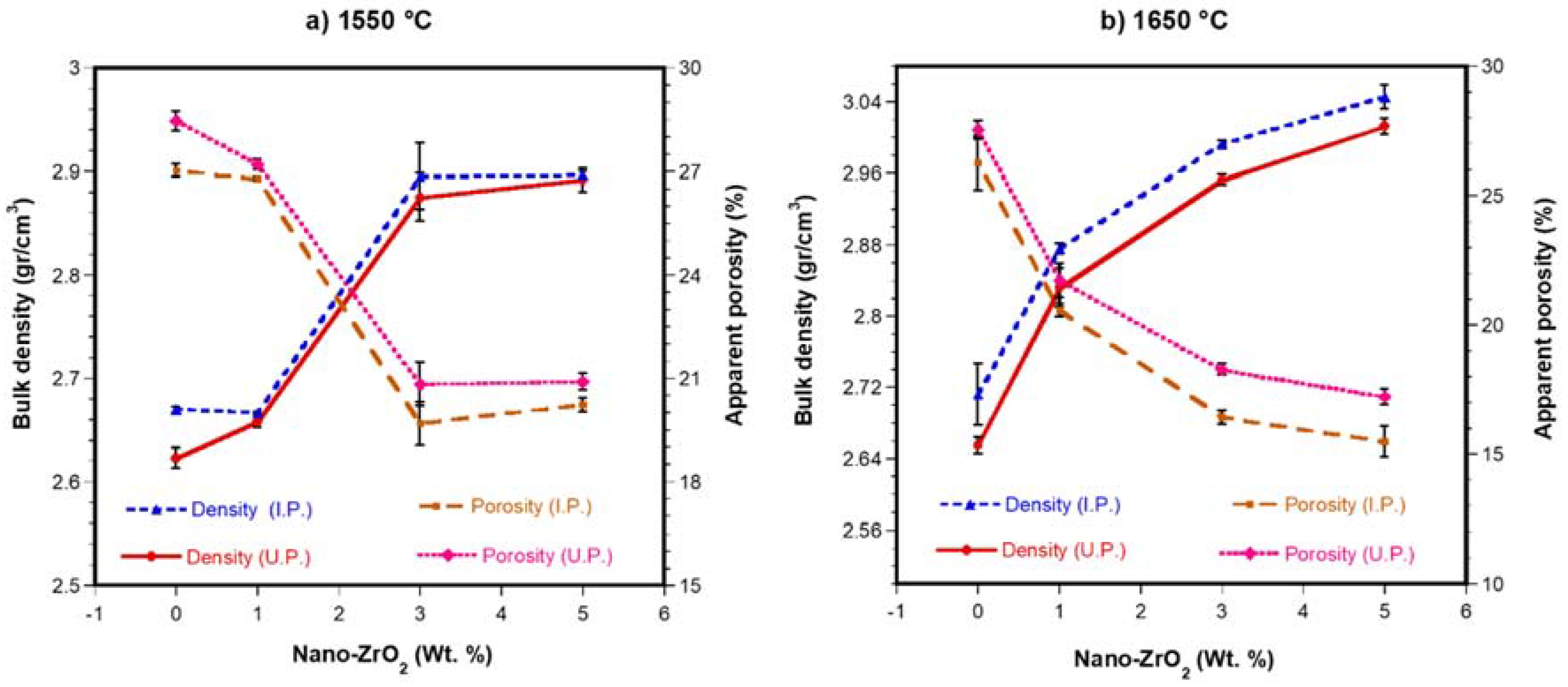
The physical properties of the refractory specimens were studied by means of the bulk density and apparent porosity tests carried out by liquid displacement (water) according to the Archimedes method (ASTM-C20). Each point of the graph (Figure 2) is the average value of six bulk density and apparent porosity tests.
Finally, to evaluate the penetration of the granulated blast furnace slag in the refractory, a slag corrosion test by molten slag was carried out. The test was performed in accordance to static finger test in the following way: a hole with a depth of 4 mm was made in each sample; later, it was filled with dust of granulated blast furnace slag with a particle size <38 µm and in a weight of 1 g; subsequently, the samples were placed in a conventional electric furnace that was heated at a rate of 5 °C/min up to 1550 °C, then the specimen was held at that temperature for 4 h, and then, it was cooled down to the room temperature at the same rate of 5 °C/min. The penetration of the molten slag on the refractory was evaluated by SEM-EDX.

3. Results and Discussion

3.1. Densification

Figure 2a shows the relationship between the percentage by weight of ZrO2 nanoparticles in the MgO matrix and the density and the apparent porosity of samples sintered at 1550 °C and pressed using two different compaction techniques (uniaxial pressing (UP) and isostatic pressing (IP)). It is possible to see that the bulk density has increased when ZrO2 nanoparticles were added (MgO enters in the lattice of ZrO2 in solid solution and, in this way, pores-holes are closed, and the densification is promoted). The values of the density for the UP samples varied from 2.62 g/cm3 (sample with only MgO, taken as reference) to 2.89 g/cm3 (5 wt. % ZrO2 nanoparticles). In the case of the IP samples, the values of the density varied from 2.67 g/cm3 (sample with only MgO, taken as reference) to 2.90 g/cm3 (5 wt. % ZrO2 nanoparticles). The density increased with the addition of ZrO2 nanoparticles, but, additionally, the density is slightly greater in the samples IP than in those UP. In the same way, the values of apparent porosity varied from 28.457% to 20.899 % for UP and from 27.028% to 20.238% and IP depending on the additions of ZrO2 in both cases (greater values without ZrO2 nanoparticles additions and the lower values with 5 wt. % of ZrO2 nanoparticles). As in the case of the density, the apparent porosity is slightly smaller in the samples IP than in those UP.
Figure 2b shows the relationship between the percentage by weight of ZrO2 nanoparticles in the MgO matrix and the density and the apparent porosity of samples sintered at 1650 °C and pressed using two different compaction techniques (uniaxial pressing (UP) and isostatic pressing (IP)). It is possible to see that the bulk density has increased when ZrO2 nanoparticles were added while, on the contrary, the apparent porosity has decreased. The values of the density for the UP samples varied from 2.65 g/cm3 (sample with only MgO, taken as reference) to 3.01 g/cm3 (5 wt. % ZrO2 nanoparticles). In the case of the IP samples, the values of the density varied from 2.71 g/cm3 (sample with only MgO, taken as reference) to 3.05 g/cm3 (5 wt. % ZrO2 nanoparticles). The density increased with the addition of ZrO2 nanoparticles, but, additionally, the density is slightly bigger in the samples IP than in those UP. In the same way, the values of apparent porosity varied from 27.540% to 17.216% for UP and from 26.248% to 15.485% and IP depending on the additions of ZrO2 nanoparticles in both cases (greater values without ZrO2 nanoparticles additions and the lower values with 5 wt. % of ZrO2 nanoparticles). As in the case of the density, the apparent porosity is slightly smaller in the samples IP than in those UP. The same as in the case of the samples sintered at 1550 °C, the values of both the density and the apparent porosity were better in the case of the IP samples than in the case of the UP samples sintered at 1650 °C.
The above-mentioned results for the density and the apparent porosity can be explained as follows:
1. The isostatic pressing (IP) technique: Although an acceptable compaction of the samples was achieved, only 4 to 7% reduction in volume was obtained from the body of the sample, when it was pressed by IP, compared with that pressed by UP The value obtained is of great interest, since it shows that when the samples were sintered, densities values were slightly higher with IP.
2. Reaction of nanoparticle by affinity (similarity) in ionic radius: Due coincidence in ionic radius, Zr4+ (0.84 Å) and Ca2+ (0.95 Å) a new phase was formed in solid solution (CaZrO3). This phase has a density of 4.95 g/cm3 [40] higher than that of the matrix (3.58 g/cm3) [4]. Also, a substitution of Mg2+ ions (0.89 Å, from the matrix) with ions of Zr4+ (0.84 Å) occurred thus stabilizing chemically the ZrO2 phase in tetragonal structure, until room temperature; the ionic compensation is made possible by oxygen vacancies. When the tetragonal zirconia is stabilized, it does not show volumetric changes and has a density (5.74 g/cm3) greater than that of the matrix.
3. Sintering process: The sintering process is affected when particles with nanometric size are used [41]. An important factor in sintering process is to lower the dihedral angle between refractory grains. This has been achieved when nanoparticles are added to the refractory matrices. Therefore, the addition of nanoparticles is effective in decreasing the dihedral angle and achieving direct bonding [20]. In this work, the above was verified when a microstructure characterized by porosity formation was obtained (from samples with 100 wt. % of MgO, sintered 1550 °C and 1650 °C), since the sintering temperature was not sufficient to densify the part (MgO has a sintering temperature ~1800 °C). With samples containing 1 to 5 wt. % of nano-ZrO2 (sintered at 1550 °C and 1650 °C) a greater surface area of the nanoparticles allowed more points of contact with the matrix particles helping to reduce the dihedral angle, to obtain samples with less porosity with improvement in physical properties (density).
Also, the high melting points of the MgO (2800 °C) [3,4,25], ZrO2 (2715 °C) [3,4] and of the phase formed in situ CaZrO3 (2340 °C) [3,4], promoted the densification of the material by sintering in solid state. The CaO/SiO2 ratio remained high (>2.8) in the raw material of MgO; no liquid phase sintered was present which would have promoted a higher density, but it would have an impact on the formation of phases of low melting point, making the refractory susceptible to resist lower temperatures. The sintering in solid state allowed to densify samples to be obtained when the free energy of the system decreases, observing growth in contact points between MgO particles and ZrO2 particles, eliminating the concentration of crystalline defects, densifying areas through surface and volumetric (mostly) migration of raw material, and thus, obtaining refractories with a high degree of direct bonds between particles. The above is explained below: It is well known that ZrO2 has a phase change above 1171 °C (from monoclinic to tetragonal phase). In addition, in MgO the diffusion of Mg ions is faster than the diffusion of O ions due to their size. Therefore, exceeding the phase change temperature indicated above, when the ZrO2 nanoparticles interacted with the MgO matrix grains, the ZrO2 showed a high susceptibility where Mg ions replace Zr ions, stabilizing the zirconia in tetragonal phase (as was demonstrated in XRD analysis). This stabilization is also caused with Ca ions (from the dispersed CaO as an impurity in the matrix) since both ions are ZrO2 stabilizers (which were detected by EDX point analysis).
The fact that Mg ions, which were originally in a cubic crystalline structure of MgO, replaced Zr ions (tetragonal structure) causes mainly two important basic sintering mechanisms within the material:
First, vacancies of magnesium cations within the cubic structure of magnesium oxide: this vacancy of cations at the periphery of the boundary of magnesium oxide grains must be replaced at high temperature with other cations that are within the volume of the crystal of magnesium oxide. Therefore, a migration to the grain boundaries is carried out, causing that the grain boundaries begin to move due to the cationic movement, which move in the same direction. Second, contraction of the material: this contraction causes the pores to close, since the boundary of one grain and another grow until they join, densifying the piece.
4. Solid solution: In the proposed process, ZrO2 is surrounded by 100% MgO. Tetragonal ZrO2 admits 10% MgO in solid solution and cubic ZrO2 admits up to 27% MgO (in weight). If ZrO2 nanoparticles are homogeneously distributed in the MgO matrix, MgO enters in the ZrO2 (in solid state by diffusion of the cations through vacancies) and pores and holes are closed, and the densification is promoted.

3.2. Phase Analysis (DRX)

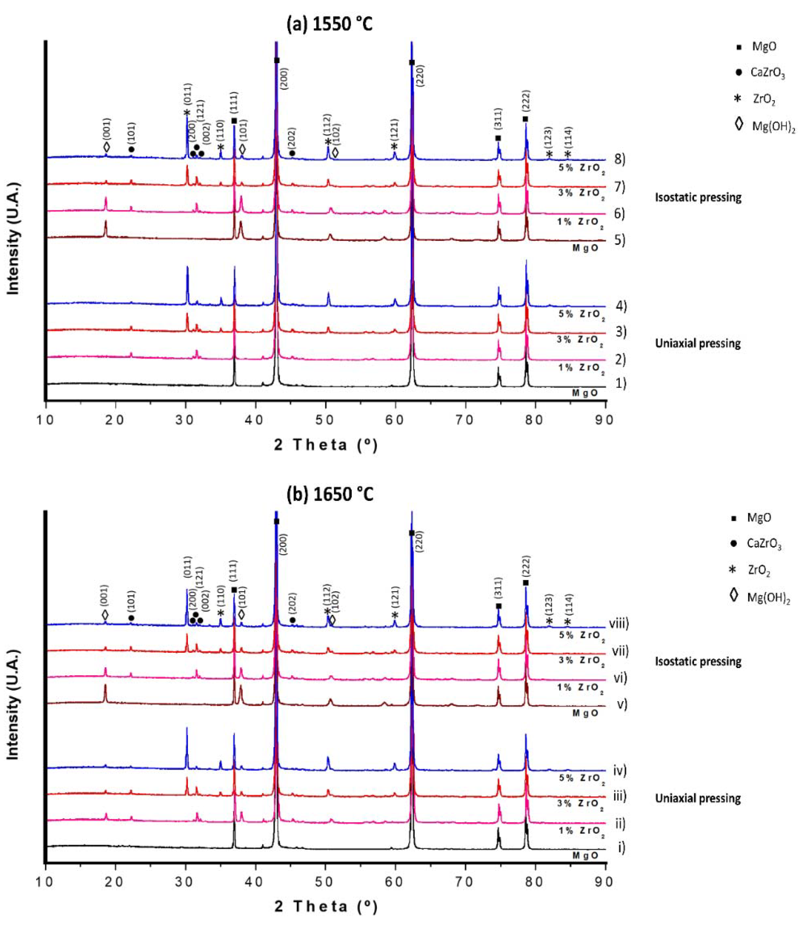
Figure 3a shows the XRD patterns of the sintered samples at 1550 °C for the specimens 100% MgO, 99 wt. % MgO-1 wt. % ZrO2, 97 wt. % MgO-3 wt. % ZrO2 and 95 wt. % MgO-5 wt. % ZrO2, pressed uniaxially in Figure 3a (1–4) and isostatically in Figure 3a (5–8).
Figure 3a (1) shows the specimen with 100% MgO (UP) where the characteristic peaks of the periclase are identified (ICDD 45-0946), being the major reflections from the planes (111), (200), (220), (311) and (222). Figure 3a (2–4) show the XRD pattern of the specimens with 1, 3, and 5 wt. % of ZrO2 nanopowders respectively (UP). New peaks can be identified being the height of those peaks greater or smaller depending on the addition of ZrO2 nanoparticles, and their position is in correlation with the standard pattern of zirconium oxide (ICDD 50-1089) that has tetragonal crystal structure where the major peaks were oriented according to the planes (011), (110), (112), (121), (123) and (114).
Figure 3a (5,6) show the XRD patterns of samples with 100% MgO and 1 wt. % ZrO2 nanoparticles respectively (IP), where MgO phase and brucite phase were identified. The brucite peaks were oriented along the (001), (101), and (102) planes, with the standard pattern of brucite (Mg(OH)2) ICDD 44-1482.
The brucite phase found in the samples was the result of two events that occurred after sintering: (i) when measuring density using the Archimedes method, the specimens were immersed in water, and therefore, they were hydrated; (ii) when the XRD analysis was performed, the powders were exposed to an environment with a high humidity index. Therefore, this phase was present in the samples. According to the literature, this phase is not part of the phases formed during sintering, where it has been reported that magnesium oxide (MgO) can be regenerated through the decomposition of any hydroxide or magnesium carbonate present, when the sample is heated below 1000 °C [42]. In the same way Wang et al., found that brucite decomposes in MgO and H2O (between 199 °C and 499 °C) [43]. This means that at the temperatures used (1550 °C and 1650 °C) this phase was not present.
Another phase identified during the XRD analyses was the CaZrO3 (ICDD35-0790) with planes diffracted at (101), (200), (121), (002) and (202). This phase is generated due to the reactivity of ZrO2 nanoparticles with CaO (found as impurity in the starting material) and is characterized by being resistant to hydration. The greatest concentration of this phase was detected in the samples with 1 and 3 wt. % of ZrO2 nanopowders, see Figure 3a (6,7), respectively (IP). In the case of the sample with 5 wt. % of ZrO2 nanopowders (IP) the main peaks correspond to the ZrO2 and MgO, having less intensity the peaks of the CaZrO3, see Figure 3a (8).
The amount of CaZrO3 did not increase with the increase of nano-ZrO2 concentration, because the CaO was an impurity (1 wt. %) of the raw material, and at higher concentration of ZrO2, the CaO particles were consumed to form CaZrO3. Only, the intensity of the peaks corresponding to ZrO2 phase increased, with ZrO2 particles concentration. On the other hand, XRD analyses were performed in samples pressed uniaxially, Figure 3b (i–iv), and isostatically, Figure 3b (v–viii), and sintered at 1650 °C. In the case of the specimens UP, the sample with 100 wt. % MgO shows only the characteristic peaks of the periclase (MgO), see Figure 3b (i). In the samples with additions of ZrO2 nanopowders (1, 3, and 5 wt. %) the peaks corresponding to the periclase (MgO), calcium zirconate (CaZrO3), zirconium oxide (ZrO2) and magnesium hydroxide (Mg(OH)2) phases were identified, see Figure 3b (ii–iv). Likewise, in the samples with 100 wt. % MgO and with 1 wt. % ZrO2 nanopowders (IP), Figure 3b (v–vi). The magnesium hydroxide (Mg (OH)2) was also detected. In the specimen with 5 wt. % of ZrO2 nanoparticles the intensity of the peaks of the calcium zirconate decreased in relation to the samples with 1 and 3 wt. % of ZrO2 nanoparticles (see Figure 3b (vi–vii)). The rest of the phases identified in the XRD analyses in the samples with 1, 3, and 5 wt. % of ZrO2 nanopowders were the same that in the case of the specimens sintered at 1550 °C (see Figure 3b (vi–viii)), the periclase (MgO), calcium zirconate (CaZrO3), zirconium oxide (ZrO2) and magnesium hydroxide (Mg(OH)2).

3.3. Microstructure Analysis (SEM-EDX)

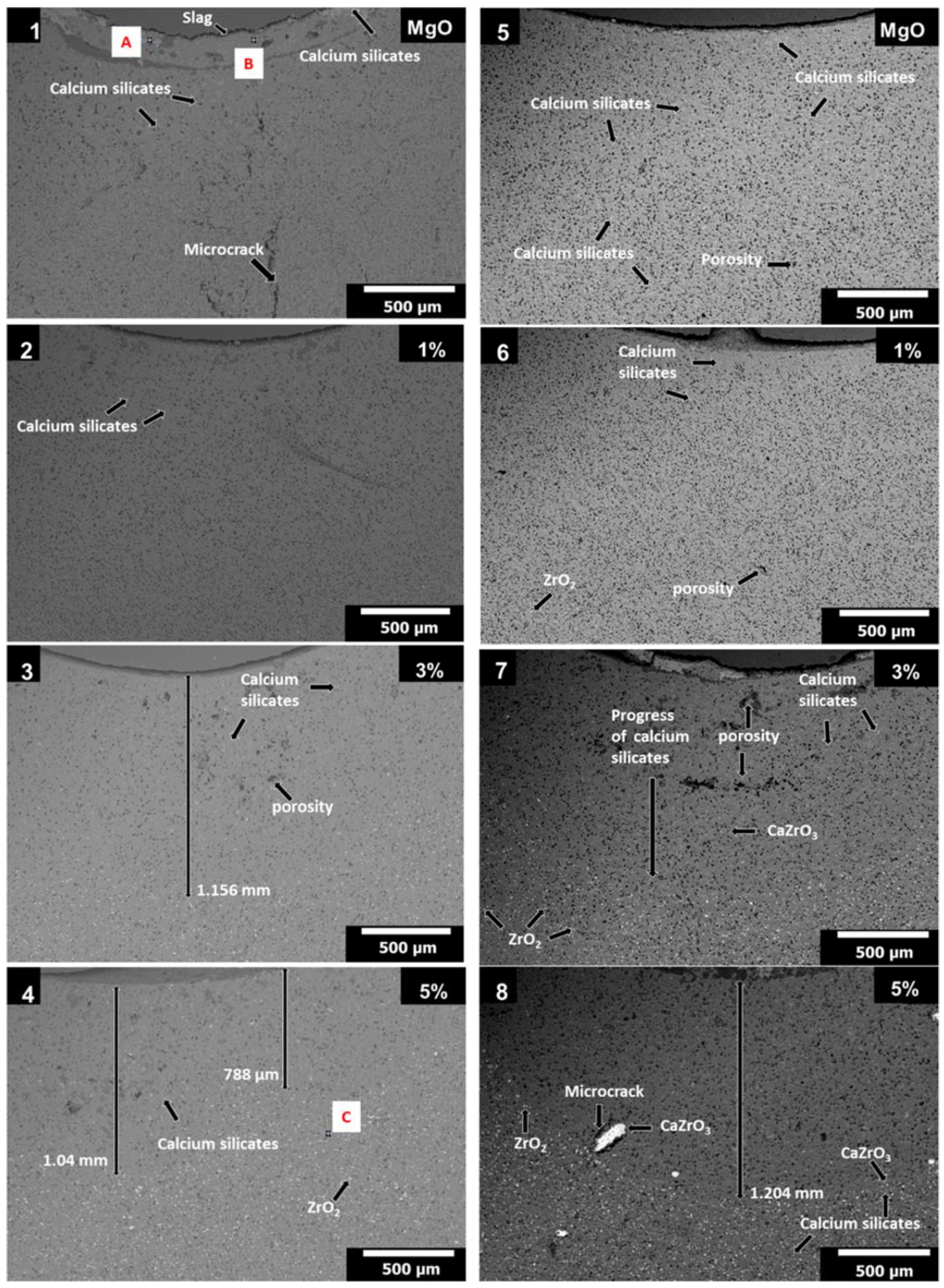
Figure 4 (1–4) correspond to samples that were first compacted using cold uniaxial pressing and then sintered at 1550 °C. Figure 4 (1) shows the microstructure of a sample with only MgO (dark gray particles, the elemental analysis of this phase is represented by the point A and Table 4) and impurities of CaO (white particles, the elemental analysis of this phase is represented by the point B and Table 4). Porosity is observed in micrographs between the grains of MgO (around a 30% of apparent porosity was observed in this sample where ZrO2 nanoparticles were not added). Figure 4 (2–4) show the microstructures of the samples with additions of ZrO2 nanoparticles (1, 3, and 5 wt. %, respectively). It is observed that increasing the content of ZrO2 nanoparticles leads to an improvement in the densification of the specimens (as mentioned, because MgO enters in the ZrO2 is solid solution and this mechanism closes pores-holes and promotes the densification). This question agrees with the information collected in Figure 2a. Even though the porosity in the specimens is reduced with respect to that of the sample without ZrO2 nanoparticles (to around 20% of apparent porosity), there are still round pores with an average size between 5 to 10 microns. The porosity observed in all these specimens can be attributed to the type of pressing that was used, which caused less surface of contact between the particles during compaction to obtain the green samples.
Figure 4 (5–8) correspond to samples that were first compacted using cold isostatic pressing and then sintered also at 1550 °C. Figure 4 (5) shows the microstructure of a sample with only MgO and impurities of CaO. The apparent porosity is still high in this sample despite the pressing method, and pores of <5µm are observed. Figure 4 (6–8) show the microstructures of samples with additions of ZrO2 nanoparticles (1, 3, and 5 wt. %, respectively). In the XRD analyses a new phase was identified (CaZrO3), and this phase is also observed in these micrographs. The CaZrO3 corresponds to the light gray zones, the ZrO2 to the white zones and the MgO to the dark gray zones, see Figure 4 (8). The presence of ZrO2 was confirmed using EDX analysis. In the case of the sample with 5 wt. % of ZrO2 nanoparticles, see point C and point D (Table 4) in Figure 4 (4,8).
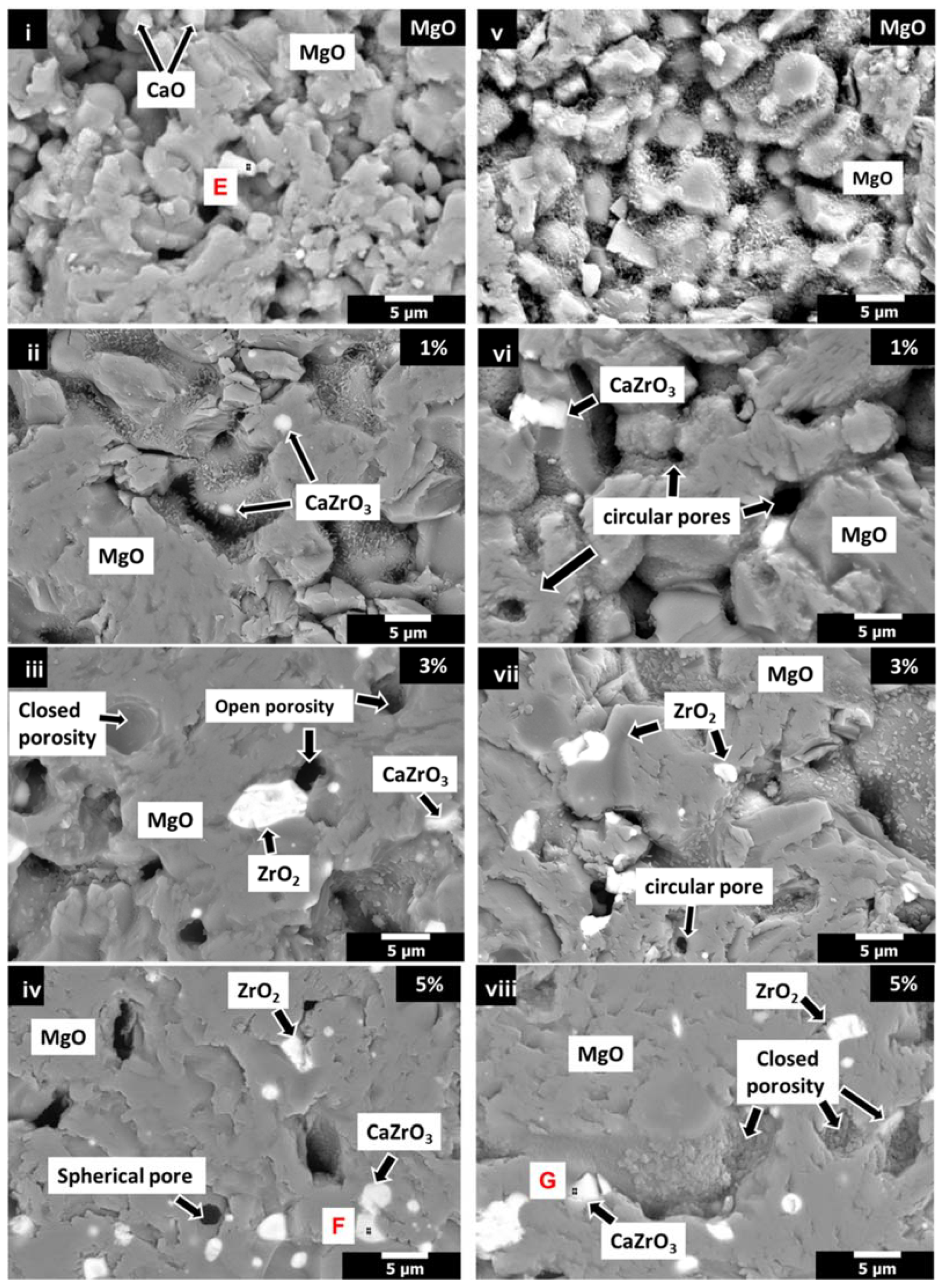
Figure 5 (i–iv) reveal the microstructure of the specimens first compacted using cold uniaxial pressing and then sintered at 1650 °C. Figure 5 (i) shows, as in the other cases, the microstructure of a specimen with only MgO and impurities of CaO (bright phase that corresponds to the point E in the point analysis Table 4). Figure 5 (ii–iv) show the microstructure of samples with additions of ZrO2 nanoparticles (1, 3, and 5 wt. %, respectively). The apparent porosity is in this case smaller than in the samples sintered at 1550 °C, with pores of <5 μm. The porosity is reduced when the amount of ZrO2 is increased. The CaZrO3 was also identified in this batch of samples, Figure 5 (iv), the EDX analysis is represented by the point F.
Figure 5 (v–viii) show the micrographs of the specimens first compacted using cold isostatic pressing and then sintered at 1650 °C. Figure 5 (v) shows the micrograph of the specimen with grains of MgO bonded (necking) although the apparent porosity (<5 μm) is still significative despite the pressing method (cold isostatic pressing) and the temperature (1650 °C). Figure 5 (vi–vii) show the microstructure of samples with addition of 1 and 3 wt. % of ZrO2 nanoparticles. There is, as in the other cases, round pores. The sintering process has several stages: early stage, orientation of particles and development of the contact between particles; middle stage, contact growth, grain boundary development (necking); next stage, isolation of the pores, and these pores acquire a rounded shape; and final stage, the pores disappear, the specimen is completely sintered. In our case, the presence of rounded porosity indicates that the process conditions were almost enough to reach the final stages of the sintering process of refractory. Figure 5 (viii) shows the SEM image of the polished surface of a sample MgO-5 wt. % ZrO2 nanoparticles. The following conclusions can be drawn: the microstructure is homogeneous, the specimen was densified although closed porosity is identified, and ZrO2 (white), MgO (dark gray) and CaZrO3 (light gray) were identified, being this last phase represented by the point G in the EDX analysis (see Table 4).
Therefore, according to the previous physical and microstructural results, in magnesia samples (i.e., 100 wt. % MgO), a microstructure with small grains was observed, because the temperature used to sinter this green compacts was not high enough to activate both the thermal process of mass transfer and the solid diffusion of the particles to obtain a coarse grained material or a densified material, since the theoretical sintering temperature of MgO (1800 °C) is higher than that used. However, when the ZrO2 nanoparticles (5 wt. %) were added to MgO samples, and considering the points indicated in 3.1. Densification about the role of the ZrO2 nanoparticles, a material with coarse grain and homogeneous microstructure is obtained, see Figure 4 (8) and Figure 5 (viii).
The applied isostatic pressure to the samples allowed to obtain better compacted green specimens after pressing, obtaining an average reduction in the volume of the sample comprised within 4 and 7% if compared to those compacted uniaxially.
Free CaO was not detected in samples with ZrO2 nanoparticles as CaZrO3 was formed (high melting point, 2340 °C [44,45]). The CaO appears as impurity in the raw material (Table 1). This gives as a result the transformation of the CaO in the samples with 1 to 5 wt. % of ZrO2 nanoparticles. This formation of CaZrO3 is positive for the refractory because it does not contain low melting point phases (as merwinitte (Ca3MgSi2O8) and monticellite (CaMgSiO4) both with initial liquid formation at 1490 °C), which would impede the use of the refractory at high temperatures. The above conclusions are supported by Rodriguez et al. [18] because there will not be the above-mentioned low melting point phases if the ratio CaO/SiO2 (in wt. %) is greater than 2.8.

3.4. Slag Corrosion Test

The corrosion resistance of the sintered specimens was evaluated by means of the slag corrosion test. The slag used in the experiments was the blast furnace slag whose composition is given in Table 1. The blast furnace slag is generated in the production of pig iron (intermediate product of the iron industry with 3.8–4.7% C and significant quantity of impurities, such as Si, P, and S, that is subsequently transformed into steel in the converter) in the blast furnace. In this furnace, coke, iron ore and fluxes/slag-forming elements are continuously supplied through the top of the furnace while hot blast (air enriched with oxygen) and pulverized coke are injected via tuyeres through the bottom of the furnace. The pig iron is produced via smelting reduction with carbon monoxide, and in a lesser extent with solid carbon. The pig iron and the slag are obtained separated at the bottom of the furnace. The pig iron is sent to the converter to obtain steel and the slag is cooled in different ways. The slag primarily consists of calcium silicates, aluminosilicates and calcium-alumina silicates, and different forms of it are produced depending on the method used to cool the molten slag: air-cooled, expanded, or foamed, pelletized, and granulated. In this experiments, granulated blast furnace slag was used, and it is obtained when the molten slag is rapidly cooled and solidified using water to obtain a glassy state, where little or no crystallization occurs.
The corrosion of the samples was evaluated using granulated blast furnace slag in specimens pressed uniaxially and isostatically and sintered at 1550 °C (Figure 6) and in specimens pressed uniaxially and isostatically and sintered at 1650 °C (Figure 7). The specimens contain MgO with different additions of ZrO2 nanopowders (0, 1, 3, and 5 wt. % of nano-ZrO2).
Figure 6 (1–4) show the microstructures of the MgO specimens with 0, 1, 3, and 5 wt. % of ZrO2 nanoparticles, respectively. The specimens were obtained by uniaxial pressing and subsequent sintering at 1550 °C. To study the effect of the blast furnace slag, a hole of ≃1.5 mm in depth and 4 mm in diameter was made where the slag was disposed. Due to the combination of high porosity and microcracks produced during the sintering process, the penetration of the slag (silicates and low melting point phases) through the MgO specimen was evident (see Figure 6 (1)). Likewise, according to EDX analysis (Table 5), the microstructural characteristics of the sample can be described as follows: white phase in acicular shape (calcium silicates, indicated by point A), dark gray phase (magnesium oxide, indicated by point B) (both points in Figure 6 (1)) and white phase in round shape (ZrO2 particles chemically attacked by the granulated blast furnace slag (see point C in Figure 6 (4))). The sample with 1 wt. % ZrO2 nanoparticles was almost completely attacked by the blast furnace as observed in Figure 6 (2). In the sample with 3 wt. % ZrO2 nanoparticles, the thickness of layer without ZrO2 particles was approximately 1.156 mm, the particles of ZrO2 and CaZrO3 were not detected in this layer due to the slag advance, see Figure 6 (3). Likewise, in the sample with 5 wt. % of ZrO2 nanoparticles, it is possible to see that in a layer between 788 µm to 1.04 mm there were not CaZrO3 and ZrO2, and after this layer, the advance of the granulated blast furnace slag was blocked by the CaZrO3 and the ZrO2, see Figure 6 (4).
Figure 6 (5–8) correspond to samples with 0, 1, 3, and 5% by weight of ZrO2 nanoparticles, respectively, that were IP and subsequently sintered at 1550 °C. As in the previous case, the specimens were attacked with granulated blast furnace slag. The attack of the slag in the samples comprising only MgO was evident in all the microstructure of the sample due to the presence of the typical phases of the slag mentioned at the beginning of this section, see Figure 6 (5). In the specimen with 1 wt. % of ZrO2 nanoparticles, the penetration of the slag (calcium silicates) is evident as is possible to see in Figure 6 (6). In the sample with 3 wt. % of ZrO2 nanoparticles, the slag penetrated in the refractory through the open porosity and the advance was stopped when it founded the CaZrO3 and ZrO2, see Figure 6 (7). In the sample with 5 wt. % of ZrO2 nanoparticles, it was observed that there was a layer without CaZrO3 and ZrO2 (1.204 mm in depth), and later these phases were detected blocking the advance of the silicates, see Figure 6 (8).
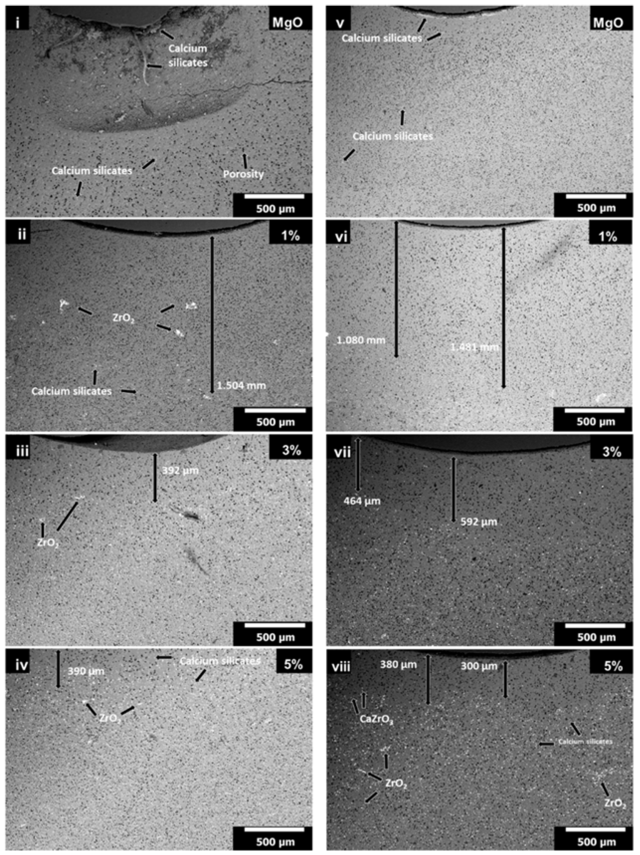
Figure 7 (i–iv) shows the slag penetration in samples compacted using uniaxial pressing and sintering at 1650 °C as a function of the additions (0, 1, 3, and 5 wt. %) of ZrO2 nanoparticles. In the case where ZrO2 nanoparticles were not added, the blast furnace slag penetration was evident through all the sample, see Figure 7 (i). In the sample with 1 wt. % of ZrO2 nanoparticles, because of an inadequate mixing of the powders, the ZrO2 nanoparticles appeared agglomerated and not dispersed through all the specimen. This gives as a result that the ZrO2 cannot stop the advance of the blast furnace slag as in the other cases and the slag reaches a depth of 1.504 mm, see Figure 7 (ii). In the case of the sample with 3 wt. % ZrO2 nanopowders, the average thickness of the layer chemically attacked without the phases of CaZrO3 and ZrO2 was 392 μm, after this point these phases blocked the advance of the slag, see Figure 7 (iii). Finally, in the sample with 5 wt. % of ZrO2 nanopowders the layer without CaZrO3 and ZrO2 was 390 μm (significantly smaller if compared with the same sample sintered at 1550 °C), see Figure 7 (iv).
Figure 7 (v–viii) show the microstructural changes resulted from the attack with granulated blast furnace slag in specimens IP and sintered at 1650 °C with different additions of ZrO2 nanoparticles (0, 1, 3, and 5 wt. % nano-ZrO2). In the sample with only MgO, the advance of the slag reached almost all the depth of the specimen, see Figure 7 (v). In the sample with 1 wt. % of ZrO2 nanoparticles the slag advanced between 1.080 mm and 1.481 mm, this penetration without ZrO2 and CaZrO3 is smaller if compared with the sample sintered at 1550 °C (full penetration of the slag). From that point, ZrO2 was detected (see white phase in Figure 7 (vi)). In the sample with 3 wt. %, the distance chemically attacked by the slag (without ZrO2 and CaZrO3, the advance of the slag is blocked when these phases appear) was between 464 and 592 μm, which is also significantly smaller than in the case of the specimen sintered at 1550 °C (approximately 1 mm), see Figure 7 (vii). Figure 7 (viii) shows the microstructure of sample of 5 wt. % ZrO2 nanoparticles chemically attacked with slag, which had the lowest penetration without ZrO2 and CaZrO3 regarding all samples with an average between 300 and 380 μm (in the same sample, IP and sintered at 1550 °C, the penetration without ZrO2 and CaZrO3 was 1.204 mm).
Summarizing, samples can be divided into three zones (see Figure 8, for the specimen with 5 wt. % ZrO2 nanoparticles, IP and sintered at 1650 °C) where:
-
Zone 1 corresponds to chemically attacked layer without CaZrO3 and ZrO2, with a distance of 347 µm. The slag (classified slightly basic) attacked and dissolved the particles of ZrO2 and CaZrO3 (chemically classified as acid and neutral, respectively), so in this area only infiltration path of the slag (in microns) was observed. Likewise, when the CaO of the slag attacked the nano-ZrO2, it helped to release the SiO2, from the same silicate crystalline structure. Both phases are more stable, so ZrO2 nanoparticles dissolved in the first micron’s depth, when the slag advanced.
-
Zone 2 corresponds to a less permeable layer where the advance of the blast furnace slag is blocked by the presence of CaZrO3 and ZrO2, with a thickness of 1.153 mm; the above is explained because, when CaO and SiO2 phases (in free form) found a great amount of ZrO2 particles enter into solid solution to form silicates of ZrO2 and MgO (i.e., these compounds enter inside the tetrahedric crystal structure formed by Si-O, since its anion has four negative charges and is compensated by the presence of alkaline earth metal ions mainly [46]). Likewise, the formation of CaZrO3, or simply ZrO2 and CaZrO3 particles surrounded by CaO and SiO2 (white dots within this zone) was also observed, making a refractory material with less permeability to infiltration of blast furnace slag.
-
Zone 3: which corresponds to the original refractory with particles of ZrO2, CaZrO3, and MgO. This zone started from an average distance of 1.5 mm with respect to the surface of contact with the slag. The points marked as A, B, and C correspond to the EDX analysis of each zone, whose results are found at the bottom of the same figure.

4. Conclusions

The effect of both the pressing method (cold uniaxial and isostatic pressing) and the sintering temperature (1550 °C and 1650 °C) was investigated in MgO refractory doped with ZrO2 nanoparticles. The conclusions of the research can be summarized as follows:
-
4 to 7% reduction in volume was obtained when the specimen was obtained by IP, compared by UP When the samples were sintered (at 1550 °C and 1650 °C), density values were almost similar using UP and IP technique, being the values of the density slightly greater when using IP.
-
5 wt. % ZrO2 nanoparticles are the optimal content of the dopant phase. The optimal process conditions require the obtaining of green compacts by cold isostatic pressing and, later, sintering the green compact at 1650 °C. This leads to well-sintered samples with low porosity and the highest density (3.05 g/cm3) of all the studied specimens. The chemical resistance of the specimens to the slag attack is also the best in this type of samples.
The penetration of the blast furnace slag did not depend only on the density of the material (concentration of ZrO2), but also on the phases formed in the refractory. Three zones are identified in the specimens subjected to the corrosion test: the first zone is characterized by the lack of ZrO2, since it was dissolved by the slag; the second zone silicates of ZrO2 and MgO are detected, but also ZrO2 and CaZrO3 that stopped the advance of the slag in the MgO refractory; finally, the third zone corresponds to the starting refractory, not attacked by the blast furnace slag.

Author Contributions

Conceptualization, C.G.-R. and L.V.G.-Q.; methodology, C.G.-R., D.F.-G., L.F.V., L.V.G.-Q. and G.A.C.-R.; validation, C.G.-R., D.F.-G. and L.F.V.; formal analysis, C.G.-R., D.F.-G., J.A.A.-M. and L.F.V.; investigation, C.G.-R., D.F.-G. and L.F.V.; resources, G.A.C.-R.; writing—original draft preparation, C.G.-R., D.F.-G. and L.V.G.-Q.; writing—review and editing, C.G.-R., J.A.A.-M., D.F.-G. and L.V.G.-Q.; visualization, C.G.-R., D.F.-G., L.F.V. and G.A.C.-R.; supervision, G.A.C.-R. and L.F.V.; project administration, C.G.-R.; funding acquisition, C.G.-R.

Funding

One of the authors, C. Gomez Rodriguez is thankful to CONACYT-México (Project No. 2018-000022-01EXTV-00052) for the financial assistance in postdoctoral stay.

Conflicts of Interest

The authors declare no conflict of interest.

References

  1. Stevens, R. An Introduction to Zirconia, 2nd ed.; Magnesium Elektron Ltd.: Clifton, UK, 1986. [Google Scholar]
  2. Wolten, G.M. Diffusionless phase transformations in zirconia and hafnia. J. Am. Ceram. Soc. 1963, 46, 418–422. [Google Scholar] [CrossRef]
  3. Lampman, S.R.; Mara, W.; Theodore, Z. Engineered Materials Handbook: Volume 4: Ceramics and Glasses, 1st ed.; CRS Press: Boca Raton, FL, USA, 1991. [Google Scholar]
  4. Schacht, C. Refractories Handbook, 1st ed.; Marcel Dekker Inc.: Pittsburg, PA, USA, 2004. [Google Scholar]
  5. Perez, I.; Moreno-Ventas, I.; Parra, R.; Ríos, G. Post-mortem study of magnesia–chromite refractory used in a submerged arc furnace in the copper-making process. J. Miner. Met. Mater. Soc. 2018, 70, 2435–2442. [Google Scholar] [CrossRef]
  6. García, L.V.; Mendivil, M.I.; Roy, T.K.D.; Castillo, G.A.; Shaji, S. Laser sintering of magnesia with nanoparticles of iron oxide and aluminum oxide. Appl. Surf. Sci. 2015, 336, 59–66. [Google Scholar] [CrossRef]
  7. Fernández-González, D.; Prazuch, J.; Ruiz-Bustinza, I.; González-Gasca, C.; Piñuela-Noval, J.; Verdeja, L.F. Solar synthesis of calcium aluminates. Sol. Energy 2018, 171, 658–666. [Google Scholar] [CrossRef]
  8. Fernández-González, D.; Ruiz-Bustinza, I.; González-Gasca, C.; Piñuela Noval, J.; Mochón-Castaños, J.; Sancho-Gorostiaga, J.; Verdeja, L.F. Concentrated solar energy applications in materials science and metallurgy. Sol. Energy 2018, 170, 520–540. [Google Scholar] [CrossRef]
  9. Martinac, V. Effect of TiO2 addition on the sintering process of magnesium oxide from seawater. In Sintering of Ceramics-New Emerging Techniques, 1st ed.; Lakshmanan, A., Ed.; IntechOpen: Rijeka, Croatia, 2012; pp. 309–322. [Google Scholar]
  10. Oghbaei, M.; Mirzaee, O. Microwave versus conventional sintering: A review of fundamentals, advantages and applications. J. Alloy. Compd. 2010, 494, 175–189. [Google Scholar] [CrossRef]
  11. Qian, B.; Shen, Z. Laser sintering of ceramics. J. Asian Ceram. Soc. 2013, 1, 315–321. [Google Scholar] [CrossRef]
  12. Zhu, T.; Li, Y.; Sang, S.; Xie, Z. A new approach to fabricate MgO-C refractories with high thermal shock resistance by adding artificial graphite. J. Eur. Ceram. Soc. 2018, 38, 2179–2185. [Google Scholar] [CrossRef]
  13. Ganesh, I.; Bhattacharjee, S.; Saha, B.P.; Johnson, R.; Rajeshwari, K.; Sengupta, R.; Ramana Rao, M.V.; Mahajan, Y.R. An efficient MgAl2O4 spinel additive for improved slag erosion and penetration resistance of high-Al2O3 and MgO–C refractories. Ceram. Int. 2002, 28, 245–253. [Google Scholar] [CrossRef]
  14. Calvo, W.A.; Ortega, P.; Velasco, M.J.; Muñoz, V.; Pena, P.; Martinez, A.G.T. Characterization of alumina-magnesia-carbon refractory bricks containing aluminium and silicon. Ceram. Int. 2018, 44, 8842–8855. [Google Scholar] [CrossRef]
  15. Behera, S.; Sarkar, R. Effect of different metal powder anti-oxidants on N220 nano carbon containing low carbon MgO-C refractory: An in-depth Investigation. Ceram. Int. 2016, 42, 18484–18494. [Google Scholar] [CrossRef]
  16. Aneziris, C.G.; Hubálková, J.; Barabás, R. Microstructure evaluation of MgO–C refractories with TiO2 and Al-additions. J. Eur. Ceram. Soc. 2007, 27, 73–78. [Google Scholar] [CrossRef]
  17. Zhang, S.; Yamaguchi, A. Effects of CaO and Al2O3 added to MgO-C refractories on MgO-C reaction. J. Ceram. Soc. Jpn. 1996, 104, 84–88. [Google Scholar] [CrossRef]
  18. Gómez Rodríguez, C.; Das Roy, T.K.; Shaji, S.; Castillo Rodríguez, G.A.; García Quiñonez, L.; Rodríguez, E.; González, J.O.; Aguilar-Martínez, J.A. Effect of addition of Al2O3 and Fe2O3 nanoparticles on the microstructural and physico-chemical evolution of dense magnesia composite. Ceram. Int. 2015, 41, 7751–7758. [Google Scholar] [CrossRef]
  19. Ghasemi-Kahrizsangi, S.; Sedeh, M.B.; Dehsheikh, H.G.; Shahraki, A.; Farooghi, M. Densification and properties of ZrO2 nanoparticles added magnesia-doloma refractories. Ceram. Int. 2016, 42, 15658–15663. [Google Scholar] [CrossRef]
  20. Ghasemi-Kahrizsangi, S.; Nemati, A.; Shahraki, A.; Farooghi, M. Densification and properties of Fe2O3 nanoparticles added CaO refractories. Ceram. Int. 2016, 42, 12270–12275. [Google Scholar] [CrossRef]
  21. Dehsheikh, H.G.; Ghasemi-Kahrizsangi, S. Performance improvement of MgO-C refractory bricks by the addition of Nano-ZrSiO4. Mater. Chem. Phys. 2017, 202, 369–376. [Google Scholar] [CrossRef]
  22. Shahraki, A.; Ghasemi-Kahrizsangi, S.; Nemati, A. Performance improvement of MgO-CaO refractories by the addition of nano-sized Al2O3. Mater. Chem. Phys. 2017, 198, 354–359. [Google Scholar] [CrossRef]
  23. Bag, M.; Adak, S.; Sarkar, R. Study on low carbon containing MgO-C refractory: Use of nano carbon. Ceram. Int. 2012, 38, 2339–2346. [Google Scholar] [CrossRef]
  24. Dehsheikh, H.G.; Ghasemi-Kahrizsangi, S.; Karamian, E. Addition impact of nano-carbon black on the performance of MgO.CaO compounds. Ceram. Int. 2018, 44, 5524–5527. [Google Scholar] [CrossRef]
  25. Ghasemi-Kahrizsangi, S.; Dehsheikh, H.G.; Karamian, E.; Boroujerdnia, M.; Payandeh, K. Effect of MgAl2O4 nanoparticles addition on the densification and properties of MgO-CaO refractories. Ceram. Int. 2017, 43, 5014–5019. [Google Scholar] [CrossRef]
  26. Ghasemi-Kahrizsangi, S.; Dehsheikh, H.G.; Karamian, E. Impact of titania nanoparticles addition on the microstructure and properties of MgO-C refractories. Ceram. Int. 2017, 43, 15472–15477. [Google Scholar] [CrossRef]
  27. Ghasemi-Kahrizsangi, S.; Shahraki, A.; Farooghi, M. Effect of nano-TiO2 additions on the densification and properties of magnesite-dolomite ceramic composites. Iran. J. Sci. Technol. 2018, 42, 567–575. [Google Scholar] [CrossRef]
  28. Ghasemi-Kahrizsangi, S.; Dehsheikh, H.G.; Boroujerdnia, M. MgO-CaO-Cr2O3 composition as a novel refractory brick: Use of Cr2O3 nanoparticles. Boletín Soc. Española Cerámica Vidr. 2017, 56, 83–89. [Google Scholar] [CrossRef]
  29. Ghasemi-Kahrizsangi, S.; Karamian, E.; Ghasemi-Kahrizsangi, A.; Desheikh, H.G.; Soheily, A. The impact of trivalent oxide nanoparticles on the microstructure and performance of magnesite-dolomite refractory bricks. Mater. Chem. Phys. 2017, 193, 413–420. [Google Scholar] [CrossRef]
  30. Ghasemi-Kahrizsangi, S.; Karamian, E.; Dehsheikh, H.G. The impact of ZrSiO4 nanoparticles addition on the microstructure and properties of dolomite based refractories. Ceram. Int. 2017, 43, 13932–13937. [Google Scholar] [CrossRef]
  31. Dehsheikh, H.G.; Ghasemi-Kahrizsangi, S. The influence of silica nanoparticles addition on the physical, mechanical, thermo-mechanical as well as microstructure of Mag-Dol refractory composites. Ceram. Int. 2017, 43, 16780–16786. [Google Scholar] [CrossRef]
  32. Kahrizsangi, S.G.; Nemati, A.; Shahraki, A.; Farooghi, M. Effect of nano-sized Fe2O3 on microstructure and hydration resistance of MgO-CaO refractories. Int. J. Nanosci. Nanotechnol. 2016, 12, 19–26. [Google Scholar]
  33. Zargar, H.R.; Oprea, C.; Oprea, G.; Troczynski, T. The effect of nano-Cr2O3 on solid-solution assisted sintering of MgO refractories. Ceram. Int. 2012, 38, 6235–6241. [Google Scholar] [CrossRef]
  34. Dudczig, S.; Veres, O.; Aneziris, C.G.; Skiera, E.; Steinbrech, R.W. Nano- and micrometre additions of SiO2, ZrO2 and TiO2 in fine grained alumina refractory ceramics for improved thermal shock performance. Ceram. Int. 2012, 38, 2011–2019. [Google Scholar] [CrossRef]
  35. Ghasemi-Kahrizsangi, S.; Dehsheikh, H.G.; Boroujerdnia, M. Effect of micro and nano-Al2O3 addition on the microstructure and properties of MgO-C refractory ceramic composite. Mater. Chem. Phys. 2017, 189, 230–236. [Google Scholar] [CrossRef]
  36. Ballester, A.; Verdeja, L.F.; Sancho, J.P. Metalurgia extractiva: Fundamentos (Volumen I), 1st ed.; Sintesis: Madrid, Spain, 2000. [Google Scholar]
  37. Puertas, F. Cementos de escorias activadas alcalinamente: Situación actual y perspectivas de futuro. Mater. Construcc. 1995, 45, 53–64. [Google Scholar] [CrossRef] [Green Version]
  38. Tiryakioğlu, M.; Dispinar, D.; Uludağ, M.; Yazman, Ş.; Gemi, L. The effect of 0.5 wt % additions of carbon nanotubes and ceramic nanoparticles on tensile properties of epoxy-matrix composites: A comparative study. Mater. Sci. Nanotechnol. 2017, 1, 15–22. [Google Scholar] [CrossRef]
  39. Assaedi, H.; Shaikh, F.U.A.; Low, I.M. Effect of nano-clay on mechanical and thermal properties of geopolymer. J. Asian Ceram. Soc. 2016, 4, 19–28. [Google Scholar] [CrossRef] [Green Version]
  40. Szczerba, J.; Pdzich, Z.; Madej, D. Synthesis of spinel-calcium zirconate materials. Ceram. Mater. 2011, 63, 27–33. [Google Scholar]
  41. Chen, M.; Lu, C.; Yu, J. Improvement in performance of MgO-CaO refractories by addition of nano-sized ZrO2. J. Eur. Ceram. Soc. 2007, 27, 4633–4638. [Google Scholar] [CrossRef]
  42. Kehl, G.L. The Principles of Metallographic Laboratory Practice, 3rd ed.; McGraw Hill Publishing Co., Ltd.: London, UK, 1949. [Google Scholar]
  43. Wang, J.A.; Novaro, O.; Bokhimi, X.; López, T.; Gomez, R.; Navarrete, J.; Llanos, M.E.; López-Salinas, E. Characterization of the thermal decomposition of brucite prepared by sol-gel technique for synthesis of nanocrystalline MgO. Mater. Lett. 1998, 35, 317–323. [Google Scholar] [CrossRef]
  44. Rodríguez, E.; Castillo, G.; Contreras, J.E.; Aguilar Martínez, J.A.; González, Y.; Guzman, A.; García Ortiz, L.I. Desarrollo de un refractario MgO-CaZrO3 dopado con MgAl2O4 para la industria cementera. CIENCIA-UANL 2011, 14, 31–38. [Google Scholar]
  45. Schafföner, S.; Aneziris, C.G.; Berek, H.; Hubálková, J.; Priese, A. Fused calcium zirconate for refractory applications. J. Eur. Ceram. Soc. 2013, 33, 3411–3418. [Google Scholar] [CrossRef]
  46. Verdeja, L.F.; Sancho, J.P.; Ballester, A.; González, R. Refractory and Ceramic Materials, 1st ed.; Sintesis: Madrid, Spain, 2008. [Google Scholar]
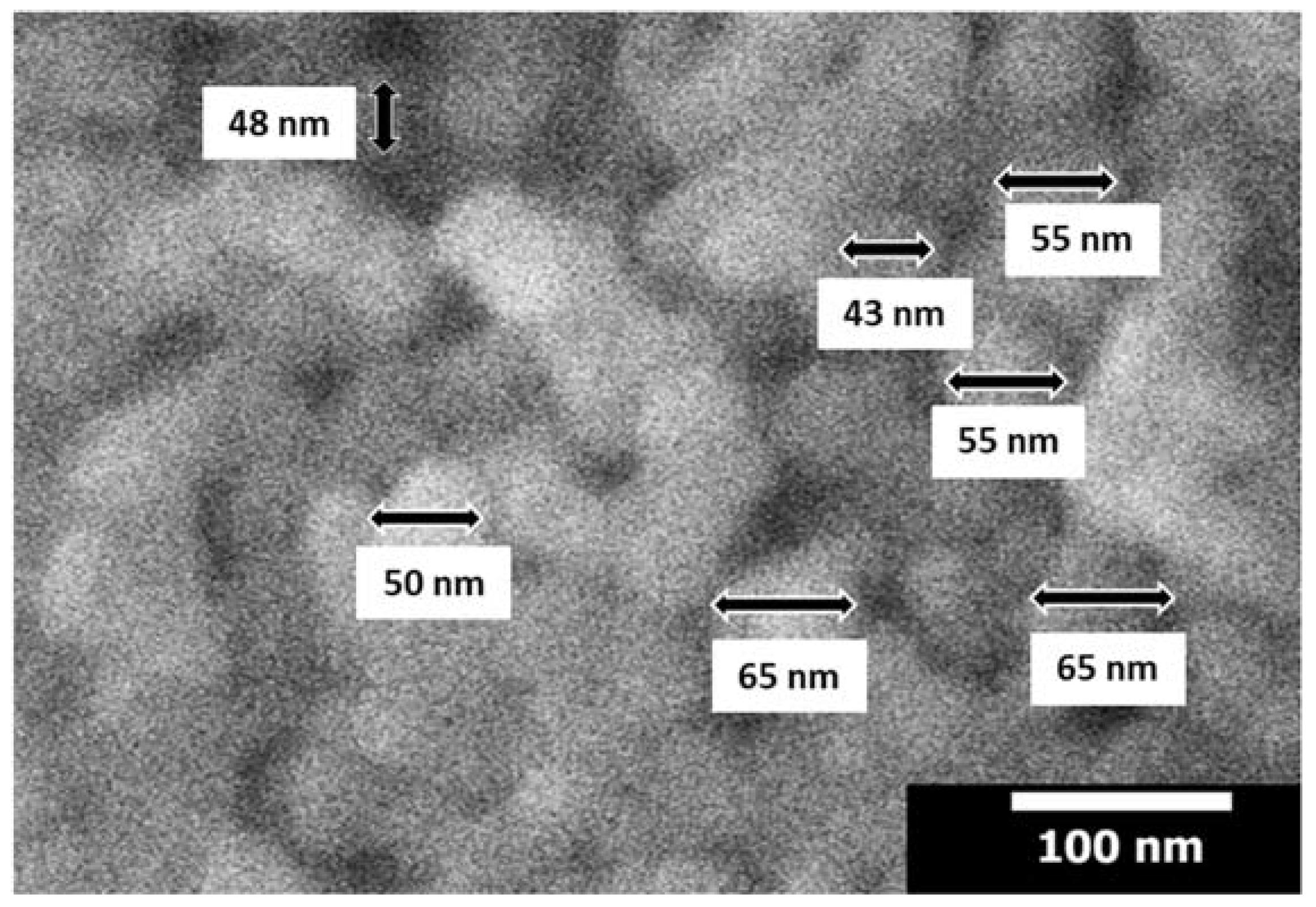
Figure 1. Scanning electron microscope image of the ZrO2 nanoparticles.
Metals 09 01297 g001
Figure 2. Variations of the bulk density and apparent porosity with respect to the content of zirconia nanoparticles, using isostatic pressure (IP) and uniaxial pressure (UP), sintered at (a) 1550 °C and (b) 1650 °C.
Metals 09 01297 g002
Figure 3. XRD patterns of samples sintered at (a) 1550 °C and (b) 1650 °C, using isostatic pressure and uniaxial pressure to samples with magnesium oxide (starting material) with variations in the concentration of zirconia nanoparticles (1, 3, and 5 wt. %), for both temperatures.
Metals 09 01297 g003
Figure 4. SEM images of refractory samples sintered at 1550 °C with uniaxial (UP) and isostatic (IP) pressure, where: (1) without nano-additions (MgO), (2) 1 wt. %, (3) 3 wt. % and (4) 5 wt. % of ZrO2 nanoparticles with UP, (5) without nano-additions (MgO), (6) 1 wt. %, (7) 3 wt. % and (8) 5 wt. % of ZrO2 nanoparticles with IP. The marked points correspond to: A = MgO, B = CaO, C = ZrO2, D = ZrO2.
Metals 09 01297 g004
Figure 5. SEM images of refractories samples sintered at 1650 °C with uniaxial (UP) and isostatic (IP) pressure, where: (i) without nano-additions (MgO), (ii) 1 wt. %, (iii) 3 wt. % and (iv) 5 wt. % of ZrO2 nanoparticles with UP, (v) without nano-additions (MgO), (vi) 1 wt. %, (vii) 3 wt. % and (viii) 5 wt. % of ZrO2 nanoparticles with IP. The marked points correspond to: E = CaO, F = CaZrO3 and G = CaZrO3.
Metals 09 01297 g005
Figure 6. SEM images of chemically attacked samples with blast furnace slag, sintered at 1550 °C, where: (1) without additions of nanoparticles (MgO), (2) 1 wt. %, (3) 3 wt. % and (4) 5 wt. % of ZrO2 nanoparticles, with UP; (5) without additions of nanoparticles (MgO), (6) 1 wt. %, (7) 3 wt. % and (8) 5 wt. % of ZrO2 nanoparticles, with IP. The marked points in Figure 6 (1) correspond to: A = Calcium silicates (CaO, SiO2).), B = Magnesium oxide (MgO), and Figure 6 (4) C = ZrO2-nanoparticles and calcium silicates (CaO, SiO2).
Metals 09 01297 g006
Figure 7. SEM images of chemically attacked samples with blast furnace slag, sintered at 1650 °C, where: (i) without additions of nanoparticles (MgO), (ii) 1 wt. %, (iii) 3 wt. % and (iv) 5 wt. % of nano ZrO2 nanoparticles, with UP, (v) without additions of nanoparticles (MgO), (vi) 1 wt. %, (vii) 3 wt. % and (viii) 5 wt. % of nano ZrO2 nanoparticles, with IP.
Metals 09 01297 g007
Figure 8. SEM image of the sample of 5 wt. % of ZrO2 nanoparticles sintered at 1650 °C with isostatic pressure, chemically attacked with slag. The three insets to the right correspond to amplifications of each zone of the sample, zone 1 (chemically attacked area), zone 2 (silicate blocking area) and zone 3 (silicate free area). Points analysis in zone 1 (point A (wt. %) = 40.81 O, 8.9 Mg, 16.14 Si, 34.15 Ca), zone 2 (point B (wt. %) = 39.64 O, 19.63 Mg, 10.1 Si, 22.3 Ca, 8.33 Zr) and zone 3 (point C (wt. %) = 33.14 O, 9.18 Mg, 1.06 Ca, 55.62 Zr).
Metals 09 01297 g008
Table 1. Chemical analysis of magnesium oxide and blast furnace slag. Physical and chemical properties of the MgO.
Raw Material and SlagChemical Analysis (wt. %)
SiO2B2O3Al2O3Fe2O3MnOMgOCaONa2OK2OTiO2P2O5L.O.I.
Magnesia0.200.010.150.12-98.501.00-----
Slag34.30-11.100.600.307.6240.000.250.400.500.134.80
Physical and chemical properties of the magnesia (MgO)
Bulk density3.48–3.52 g/cm3
Melting point2800 °C
Boiling point3600 °C
pH10.5
Table 2. Properties of the ZrO2 nanoparticles.
PowderSize (nm)Purity (%)Relative Density (g/cm3)Specific Surface Area (m2/g)Color
ZrO2 nanoparticles<100>995.89≥25White
Table 3. Chemical composition with sample code, isostatically pressed (IP) and uniaxially pressed (UP), sintered at 1550 °C and 1650 °C.
Chemical Composition (wt. %))Temperature and Pressing Methods
MgOZrO2 NanoparticlesIP 1550 °CUP 1550 °CUP 1650 °CIP 1650 °C
991CGR1–6CGR19–24CGR37–42CGR55–60
973CGR7–12CGR25–30CGR43–48CGR61–66
955CGR13–18CGR31–36CGR49–54CGR67–72
1000CGRi–viCGRvii–xiiCGRxiii–xviiiCGRxix–xxiv
Table 4. Point analysis (EDX) of samples sintered at 1550 °C and 1650 °C.
FigureFigure 4 (1)Figure 4 (1)Figure 4 (4)Figure 4 (8)Figure 5 (i)Figure 5 (iv)Figure 5 (viii)
ElementPoint APoint BPoint CPoint DPoint EPoint FPoint G
wt. %at. %wt. %at. %wt. %at. %wt. %at. %wt. %at. %wt. %at. %wt. %at. %
O36.546.65773.6129.2563.7136.1269.960.1876.7235.767.741.771.65
Mg63.553.412.6610.757.8111.198.1810.419.157.674.585.716.587.44
Ca--30.3415.642.171.891.831.4130.6715.6115.8712.0113.879.51
Zr----60.7723.2153.8718.28--43.8514.5837.8511.4
Table 5. Point analysis (EDX) of samples tested with blast furnace slag: (A) and (B) points for sample of MgO and point (C) for sample with 5 wt. % of ZrO2 nanoparticles, both with uniaxial pressure and sintered at 1550 °C.
FigureFigure 6 (1)Figure 6 (1)Figure 6 (4)
ElementPoint APoint BPoint C
wt. %at. %wt. %at. %wt. %at. %
O40.8359.5944.2554.6941.1161.23
Mg4.264.0955.7145.3124.7724.28
Si17.3614.43--5.915.02
Ca37.5621.89--6.313.75
Zr----21.95.72