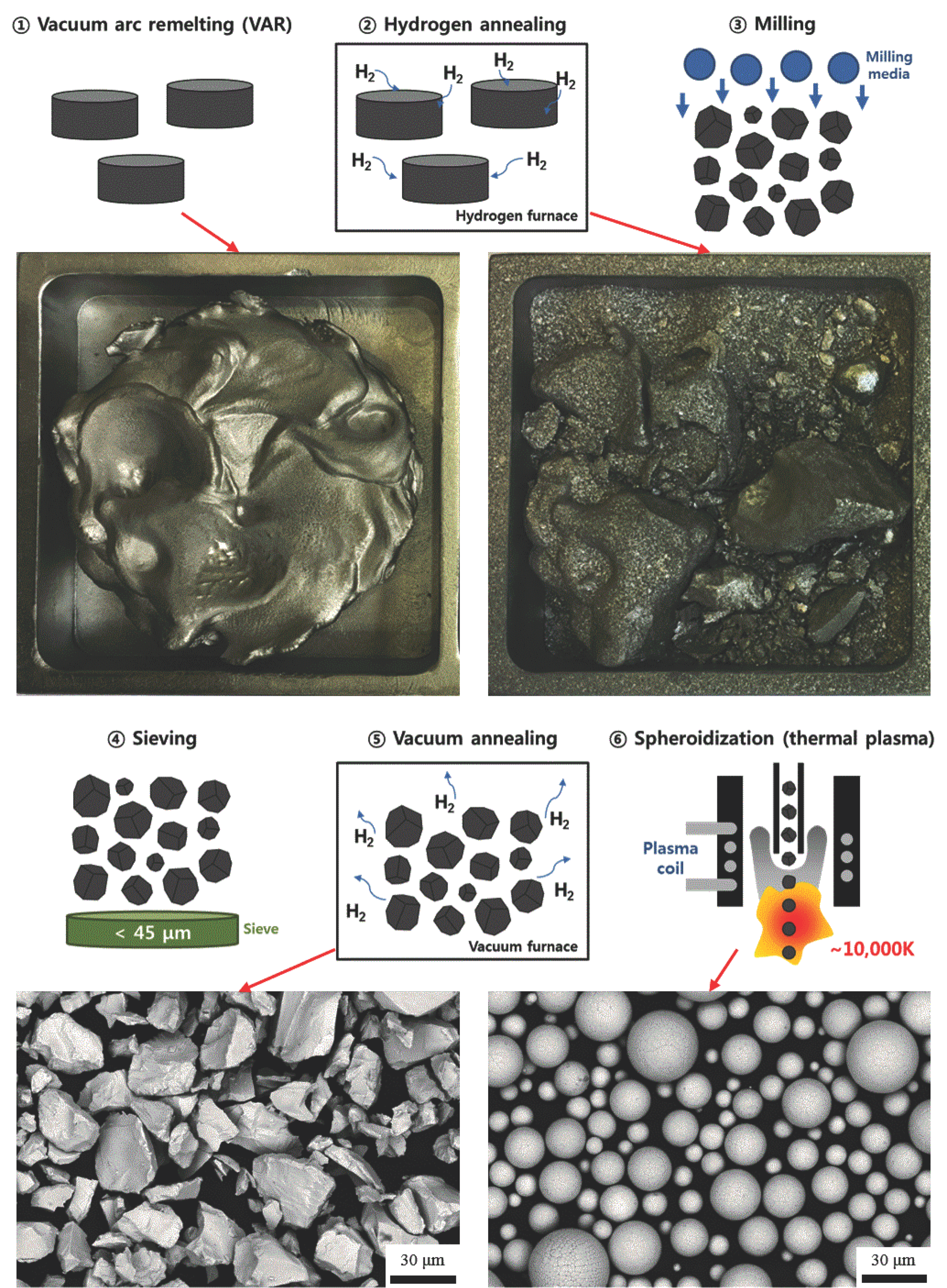
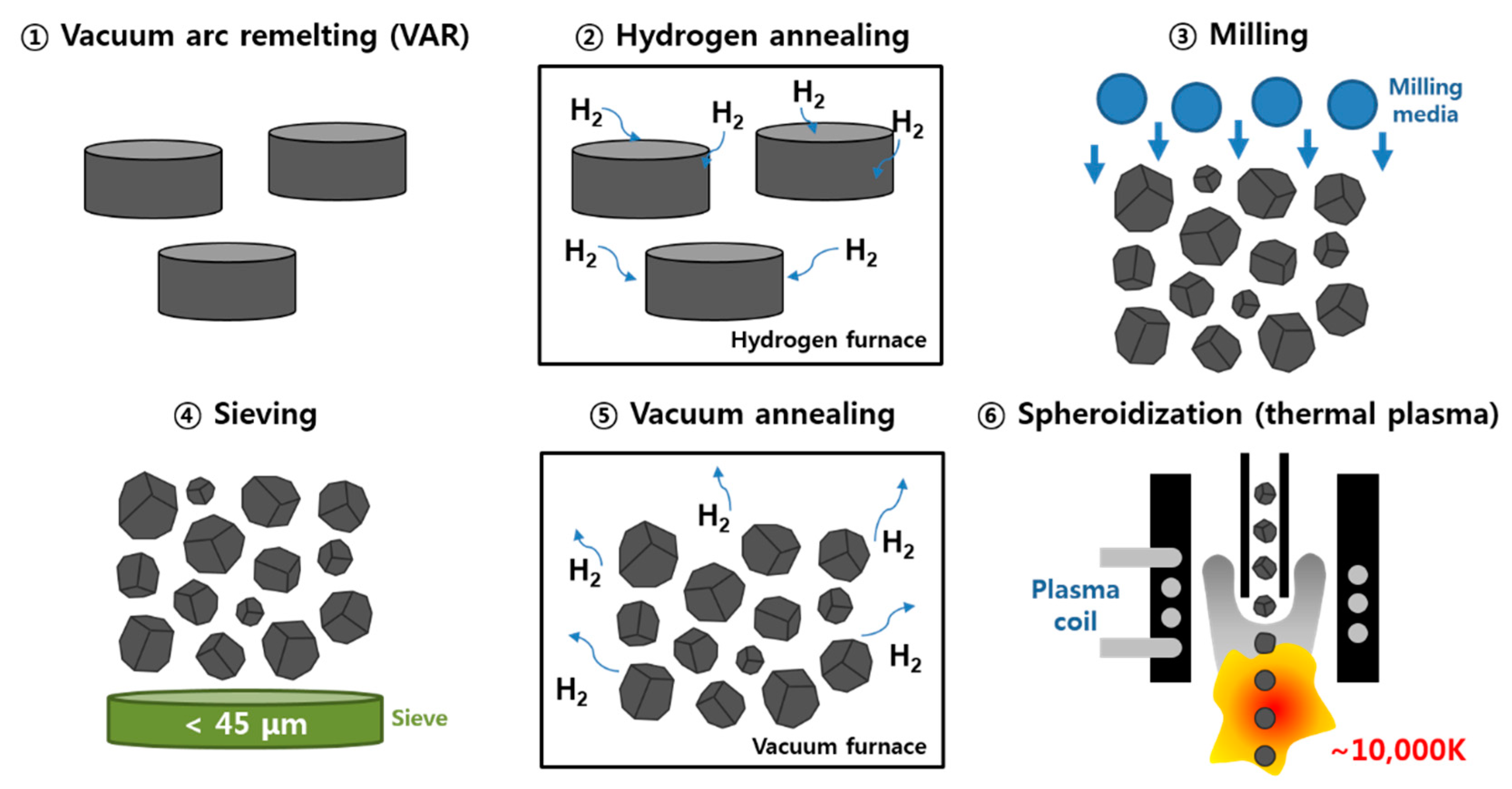
Synthesis of Spherical V-Nb-Mo-Ta-W High-Entropy Alloy Powder Using Hydrogen Embrittlement and Spheroidization by Thermal Plasma


 and
and
Abstract

1. Introduction
2. Materials and Methods
3. Results and Discussion
4. Conclusions
Author Contributions
Funding
Acknowledgments
Conflicts of Interest
References
- Yeh, J.W.; Chen, S.K.; Lin, S.J.; Gan, J.Y.; Chin, T.S.; Shun, T.T.; Tsau, C.H.; Chang, S.Y. Nanostructured high-entropy alloys with multiple principal elements: Novel alloy design concepts and outcomes. Adv. Eng. Mater. 2004, 6, 299–303. [Google Scholar] [CrossRef]
- Youssef, K.M.; Zaddach, A.J.; Niu, C.; Irving, D.L.; Koch, C.C. A novel low-density, high-hardness, high-entropy alloy with close-packed single-phase nanocrystalline structures. Mater. Res. Lett. 2015, 3, 95–99. [Google Scholar] [CrossRef]
- Yu, P.F.; Zhang, L.J.; Cheng, H.; Zhang, H.; Ma, M.Z.; Li, Y.C.; Li, G.; Liaw, P.K.; Liu, R.P. The high-entropy alloys with high hardness and soft magnetic property prepared by mechanical alloying and high-pressure sintering. Intermetallics 2016, 70, 82–87. [Google Scholar] [CrossRef]
- Yeh, J.; Chen, S.; Gan, J.; Lin, S.; Chin, T. Formation of simple crystal structures in Cu-Co-Ni-Cr-Al-Fe-Ti-V alloys with multiprincipal metallic elements. Metall. Mater. Trans. A 2010, 35, 2533–2536. [Google Scholar] [CrossRef]
- Zhou, Y.J.; Zhang, Y.; Wang, Y.L.; Chen, G.L. Solid solution alloys of AlCoCrFeNiTix with excellent room-temperature. Appl. Phys. Lett. 2014, 90, 181904. [Google Scholar] [CrossRef]
- Fu, Z.; Chen, W.; Fang, S.; Zhang, D.; Xiao, H.; Zhu, D. Alloying behavior and deformation twinning in a CoNiFeCrAl0. 6Ti0. 4 high entropy alloy processed by spark plasma sintering. J. Alloys Compd. 2013, 553, 316–323. [Google Scholar] [CrossRef]
- Chou, H.P.; Chang, Y.S.; Chen, S.K.; Yeh, J.W. Microstructure, thermophysical and electrical properties in AlxCoCrFeNi (0 ≤ x ≤ 2) high-entropy alloys. Mater. Sci. Eng. B. 2009, 163, 184–189. [Google Scholar] [CrossRef]
- Fan, Z.; Wang, H.; Wu, Y.; Liu, X.; Lu, Z. Thermoelectric performance of PbSnTeSe high-entropy alloys. Mater. Res. Lett. 2017, 5, 187–194. [Google Scholar] [CrossRef]
- Wu, W.H.; Yang, C.C.; Yeh, L.W. Industrial development of high-entropy alloys. Ann. Chim. Des Mater. 2006, 31, 737–747. [Google Scholar] [CrossRef]
- Schuh, B.; Mendez-Martin, F.; Völker, B.; George, E.P.; Clemens, H.; Pippan, R.; Hohenwarter, A. Mechanical properties, microstructure and thermal stability of a nanocrystalline CoCrFeMnNi high-entropy alloy after severe plastic deformation. Acta Mater. 2015, 96, 258–268. [Google Scholar] [CrossRef]
- Senkov, O.N.; Wilks, G.B.; Scott, J.M.; Miracle, D.B. Mechanical properties of Nb25Mo25Ta25W25 and V20Nb20Mo20Ta20W20 refractory high entropy alloys. Intermetallics 2011, 19, 698–706. [Google Scholar] [CrossRef]
- Senkov, O.N.; Wilks, G.B.; Miracle, D.B.; Chuang, C.P.; Liaw, P.K. Refractory high-entropy alloys. Intermetallics 2010, 18, 1758–1765. [Google Scholar] [CrossRef]
- Stepanov, N.D.; Shaysultanov, D.G.; Salishchev, G.A.; Tikhonovsky, M.A. Structure and mechanical properties of a light-weight AlNbTiV high entropy alloy. Mater. Lett. 2015, 142, 153–155. [Google Scholar] [CrossRef]
- Chen, Y.Y.; Duval, T.; Hung, U.D.; Yeh, J.W.; Shih, H.C. Microstructure and electrochemical properties of high entropy alloys—A comparison with type-304 stainless steel. Corros. Sci. 2005, 47, 2257–2279. [Google Scholar] [CrossRef]
- Hsu, Y.J.; Chiang, W.C.; Wu, J.K. Corrosion behavior of FeCoNiCrCux high-entropy alloys in 3.5% sodium chloride solution. Mater. Chem. Phys. 2005, 92, 112–117. [Google Scholar] [CrossRef]
- Shi, Y.; Yang, B.; Liaw, P. Corrosion-resistant high-entropy alloys: A review. Metals 2017, 7, 43. [Google Scholar] [CrossRef]
- Hsu, C.Y.; Yeh, J.W.; Chen, S.K.; Shun, T.T. Wear resistance and high-temperature compression strength of Fcc CuCoNiCrAl0.5Fe alloy with boron addition. Metall. Mater. Trans. A 2004, 35, 1465–1469. [Google Scholar] [CrossRef]
- Chuang, M.H.; Tsai, M.H.; Wang, W.R.; Lin, S.J.; Yeh, J.W. Microstructure and wear behavior of AlxCo1. 5CrFeNi1. 5Tiy high-entropy alloys. Acta Mater. 2011, 59, 6308–6317. [Google Scholar] [CrossRef]
- Tsai, M.H.; Yeh, J.W.; Gan, J.Y. Diffusion barrier properties of AlMoNbSiTaTiVZr high-entropy alloy layer between copper and silicon. Thin Solid Films 2008, 516, 5527–5530. [Google Scholar] [CrossRef]
- Chang, S.Y.; Wang, C.Y.; Chen, M.K.; Li, C.E. Ru incorporation on marked enhancement of diffusion resistance of multi-component alloy barrier layers. J. Alloys Compd. 2011, 509, L85–L89. [Google Scholar] [CrossRef]
- Han, Z.D.; Chen, N.; Zhao, S.F.; Fan, L.W.; Yang, G.N.; Shao, Y.; Yao, K.F. Effect of Ti additions on mechanical properties of NbMoTaW and VNbMoTaW refractory high entropy alloys. Intermetallics 2017, 84, 153–157. [Google Scholar] [CrossRef]
- Xin, S.W.; Zhang, M.; Yang, T.T.; Zhao, Y.Y.; Sun, B.R.; Shen, T.D. Ultrahard bulk nanocrystalline VNbMoTaW high-entropy alloy. J. Alloys Compd. 2018, 769, 597–604. [Google Scholar] [CrossRef]
- Nam, H.; Park, C.; Kim, C.; Kim, H.; Kang, N. Effect of post weld heat treatment on weldability of high entropy alloy welds. Sci. Technol. Weld. Join. 2018, 23, 420–427. [Google Scholar] [CrossRef]
- Thompson, S.M.; Bian, L.; Shamsaei, N.; Yadollahi, A. An overview of Direct Laser Deposition for additive manufacturing; Part I: Transport phenomena, modeling and diagnostics. Addit. Manuf. 2015, 8, 36–62. [Google Scholar] [CrossRef]
- Todd, I.; Sidambe, A.T. Developments in metal injection moulding (MIM). In Advances in Powder Metallurgy; Woodhead Publishing: Sawston, UK, 2013; pp. 109–146. [Google Scholar]
- Robertson, I.M.; Sofronis, P.; Nagao, A.; Martin, M.L.; Wang, S.; Gross, D.W.; Nygren, K.E. Hydrogen embrittlement understood. Metall. Mater. Trans. A 2015, 46, 2323–2341. [Google Scholar] [CrossRef]
- Popov, B.N.; Lee, J.W.; Djukic, M.B. Hydrogen permeation and hydrogen-induced cracking. In Handbook of Environmental Degradation of Materials; William Andrew Publishing: Norwich, NY, USA, 2018; pp. 133–162. [Google Scholar]
- Djukic, M.B.; Bakic, G.M.; Zeravcic, V.S.; Sedmak, A.; Rajicic, B. The synergistic action and interplay of hydrogen embrittlement mechanisms in steels and iron: localized plasticity and decohesion. Eng. Fract. Mech. 2019, 216, 106528. [Google Scholar] [CrossRef]
- Ichii, K.; Koyama, M.; Tasan, C.C.; Tsuzaki, K. Comparative study of hydrogen embrittlement in stable and metastable high-entropy alloys. Scr. Mater. 2018, 150, 74–77. [Google Scholar] [CrossRef]
- Zhao, Y.K.; Lee, D.H.; Seok, M.Y.; Lee, J.A.; Phaniraj, M.P.; Suh, J.Y.; Ha, H.Y.; Kim, J.Y.; Ramamurty, U.; Jang, J.I. Resistance of CoCrFeMnNi high-entropy alloy to gaseous hydrogen embrittlement. Scr. Mater. 2017, 135, 54–58. [Google Scholar] [CrossRef]
- Nygren, K.E.; Wang, S.; Bertsch, K.M.; Bei, H.B.; Nagao, A.; Robertson, I.M. Hydrogen embrittlement of the equi-molar FeNiCoCr alloy. Acta Mater. 2018, 157, 218–227. [Google Scholar] [CrossRef]
- Luo, H.; Li, Z.M.; Lu, W.J.; Ponge, D.; Raabe, D. Hydrogen embrittlement of an interstitial equimolar high-entropy alloy. Corros. Sci. 2018, 136, 403–408. [Google Scholar] [CrossRef]
- Moreen, H.A.; Taggart, R.; Polonis, D.H. A model for the prediction of lattice parameters of solid solutions. Metall. Trans. 1971, 2, 265–268. [Google Scholar] [CrossRef]
- Owen, C.V.; Scott, T.E. Relation between hydrogen embrittlement and the formation of hydride in the group V transition metals. Metall. Mater. Trans. B 1972, 3, 1715–1726. [Google Scholar] [CrossRef]
- Park, K.B.; Park, J.M.; Choi, J.; Kang, J.-W.; Lee, S.Y.; Park, K.; Lee, T.-W.; Na, T.-W.; Park, H.-K. Preparation of Nb-silicide based alloy powder by hydrogenation-dehydrogenation reaction. Int. J. Refract. Met. Hard Mater. 2018, 76, 180–184. [Google Scholar] [CrossRef]
- Cotterill, P. The hydrogen embrittlement of metals. Prog. Mater. Sci. 1961, 9, 205–301. [Google Scholar] [CrossRef]
- Azevedo, C.R.F.; Rodrigues, D.; Neto, F.B. Ti-Al-V powder metallurgy (PM) via the hydrogenation--dehydrogenation (HDH) process. J. Alloys Compd. 2003, 353, 217–227. [Google Scholar] [CrossRef]
- Oh, J.M.; Roh, K.M.; Lee, B.K.; Suh, C.Y.; Kim, W.; Kwon, H.; Lim, J.W. Preparation of low oxygen content alloy powder from Ti binary alloy scrap by hydrogenation-dehydrogenation and deoxidation process. J. Alloys Compd. 2014, 593, 61–66. [Google Scholar] [CrossRef]
- Boulos, M.I. The role of transport phenomena and modeling in the development of thermal plasma technology. Plasma Chem. Plasma Process. 2016, 36, 3–28. [Google Scholar] [CrossRef]
- Grant, N.J. Rapid solidification of metallic particulates. JOM 1983, 35, 20–27. [Google Scholar] [CrossRef]


| Element | Ta | W | Nb | Mo | V |
|---|---|---|---|---|---|
| Atomic% | 21.07 | 19.75 | 19.3 | 20.39 | 19.49 |
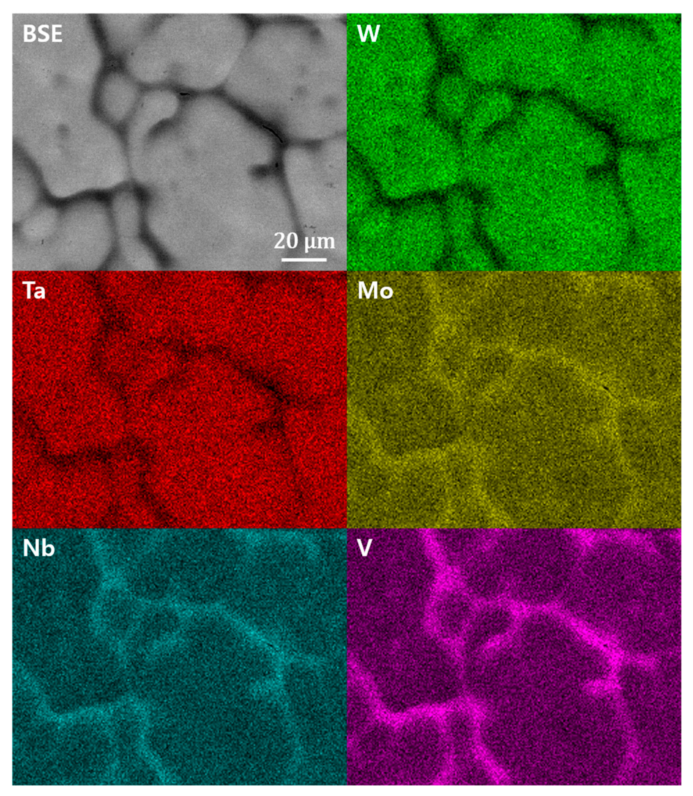
| Sample | V | Nb | Mo | Ta | W | ||
|---|---|---|---|---|---|---|---|
| Ingot | Dendrite arm | wt% | 6.00 | 14.43 | 15.60 | 30.86 | 33.11 |
| at% | 14.97 | 19.75 | 20.68 | 21.34 | 23.26 | ||
| Interdendritic region | wt% | 18.61 | 19.12 | 17.63 | 27.46 | 17.19 | |
| at% | 36.56 | 20.59 | 18.39 | 14.95 | 9.51 | ||
| Spheroidized powder | Dendrite arm | wt% | 4.00 | 12.52 | 13.73 | 30.55 | 39.21 |
| at% | 10.62 | 18.23 | 19.35 | 22.48 | 29.31 | ||
| Interdendritic region | wt% | 17.04 | 24.31 | 19.84 | 22.47 | 16.34 | |
| at% | 32.94 | 25.76 | 20.37 | 12.03 | 8.89 | ||
| Sample | Composition | Oxygen | Nitrogen | Hydrogen |
|---|---|---|---|---|
| Ingot | wt% | 0.065 | 0.004 | 0.0009 |
| at% | 0.488 | 0.034 | 0.1074 | |
| Hydrogen-annealed powder | wt% | 0.066 | 0.011 | 0.1033 |
| at% | 0.442 | 0.084 | 11.0634 | |
| Vacuum-annealed powder | wt% | 0.067 | 0.004 | 0.0002 |
| at% | 0.504 | 0.034 | 0.0241 | |
| Spheroidized powder | wt% | 0.042 | 0.005 | 0.0003 |
| at% | 0.316 | 0.043 | 0.0359 |
© 2019 by the authors. Licensee MDPI, Basel, Switzerland. This article is an open access article distributed under the terms and conditions of the Creative Commons Attribution (CC BY) license (http://creativecommons.org/licenses/by/4.0/).
Share and Cite
Lee, W.-H.; Park, K.B.; Yi, K.-W.; Lee, S.Y.; Park, K.; Lee, T.W.; Na, T.-W.; Park, H.-K. Synthesis of Spherical V-Nb-Mo-Ta-W High-Entropy Alloy Powder Using Hydrogen Embrittlement and Spheroidization by Thermal Plasma. Metals 2019, 9, 1296. https://doi.org/10.3390/met9121296
Lee W-H, Park KB, Yi K-W, Lee SY, Park K, Lee TW, Na T-W, Park H-K. Synthesis of Spherical V-Nb-Mo-Ta-W High-Entropy Alloy Powder Using Hydrogen Embrittlement and Spheroidization by Thermal Plasma. Metals. 2019; 9(12):1296. https://doi.org/10.3390/met9121296
Chicago/Turabian StyleLee, Won-Hyuk, Ki Beom Park, Kyung-Woo Yi, Sung Yong Lee, Kwangsuk Park, Taeg Woo Lee, Tae-Wook Na, and Hyung-Ki Park. 2019. "Synthesis of Spherical V-Nb-Mo-Ta-W High-Entropy Alloy Powder Using Hydrogen Embrittlement and Spheroidization by Thermal Plasma" Metals 9, no. 12: 1296. https://doi.org/10.3390/met9121296
APA StyleLee, W.-H., Park, K. B., Yi, K.-W., Lee, S. Y., Park, K., Lee, T. W., Na, T.-W., & Park, H.-K. (2019). Synthesis of Spherical V-Nb-Mo-Ta-W High-Entropy Alloy Powder Using Hydrogen Embrittlement and Spheroidization by Thermal Plasma. Metals, 9(12), 1296. https://doi.org/10.3390/met9121296