Article

Experimental Optimization of Nimonic 263 Laser Cutting Using a Particle Swarm Approach

by
Tatjana Sibalija
1,
Sanja Petronic
2,* and
Dubravka Milovanovic
3
1
Faculty of Information Technology, Faculty of Management, Belgrade Metropolitan University, Tadeusa Koscuska 63, 11000 Belgrade, Serbia
2
Innovation Centre Faculty of Mechanical Engineering in Belgrade, Kraljice Marije 16, 11120 Belgrade, Serbia
3
Institute of General and Physical Chemistry, Studentski trg 12/V, 11000 Belgrade, Serbia
*
Author to whom correspondence should be addressed.
Metals 2019, 9(11), 1147; https://doi.org/10.3390/met9111147
Submission received: 1 October 2019 / Revised: 17 October 2019 / Accepted: 23 October 2019 / Published: 25 October 2019

Abstract

:
This paper presents an experimental study carried out on Nimonic 263 alloy sheets to determine the optimal combination of laser cutting control factors (assisted gas pressure, beam focus position, laser power, and cutting speed), with respect to multiple characteristics of the cut area. With the aim of designing laser cutting parameters that satisfy the specifications of multiple responses, an advanced multiresponse optimization methodology was used. After the processing of experimental data to develop the process measure using statistical methods, the functional relationship between cutting parameters and the process measure was determined by artificial neural networks (ANNs). Using the trained ANN model, particle swarm optimization (PSO) was employed to find the optimal values of laser cutting parameters. Since the effectiveness of PSO could be affected by its parameter tuning, the settings of PSO algorithm-specific parameters were analyzed in detail. The optimal laser cutting parameters proposed by PSO were implemented in the validation run, showing the superior cut characteristics produced by the optimized parameters and proving the efficacy of the suggested approach in practice. In particular, it is demonstrated that the quality of the Nimonic 263 cut area and the microstructure were significantly improved, as well as the mechanical characteristics.

1. Introduction

Nickel-based superalloys consist of over 50% nickel and 8–12 alloying elements added to improve their characteristics. Due to their very good performance at high temperatures and pressures, there is great demand for them in the aerospace, processing, and manufacturing industries [1]. The Nimonic 263 alloy belongs to the nickel-based superalloy group. Owing to very good mechanical properties, good corrosion resistance and oxidation resistance, the workpieces made of Nimonic 263 superalloy are able to endure very demanding operating conditions, including high temperature and pressure [2]. Further improvement of the characteristics of Nimonic 263 parts is often a very demanding task. The laser cutting quality when processing Nimonic 263 parts depends on the laser cutting parameter selection and material properties. The important output characteristics are the surface roughness, material removal rate (MRR), kerf width and taper, and the absence of a grate. The kerf width and taper indicate the processing accuracy; the rate and economics of production are expressed via MRR [3]; the surface roughness determines the local stress concentration.
Parameters of the laser cutting process must be properly tuned in order to obtain the desired outputs. The laser power must be sufficient to enable the cutting; the cutting speed should be high enough to prevent the diffusion of heat in a material and to form a broad heat-affected zone (HAZ) [4]. The assisting gas is very important for producing a high-quality cut without a grate, since it does not permit molten material droplets’ solidification onto the cut surface. The cutting speed must be balanced; if excessive speed is used the grate would remain, while, with a very low speed, the edge quality of the cut would be affected and a wide HAZ would form [5].
The cutting control factors considered in this study are the assisting gas pressure, the position of the beam focus, the laser power, and the cutting speed. At the output, seven responses of the cut area are observed. Since the process is characterized by multiple parameters and responses, an advanced optimization methodology is needed to obtain the optimal cutting setting that satisfies the specifications for multiple, correlated responses. Simulated annealing (SA) and a genetic algorithm (GA) have been employed previously, and it has been demonstrated that SA outperformed GA in the proposed method [6]. Particle swarm optimization (PSO) is used in this study and benchmarked with SA in terms of the quality, i.e., the accuracy of the obtained optimum, the effects of the algorithm’s parameters on the obtained optimum, and the convergence speed. Since metaheuristic algorithms must be adequately tuned to obtain the right solution, the setting of the major PSO algorithm’s parameters is studied in detail to evaluate their influence on the optimal solution.
A vast majority of the existing studies, including both nonsystematic and designed experimentations, consider only one or two characteristics of a cut. On the contrary, this paper presents a comprehensive and systematic experimental study of the major laser cutting parameters in processing Ni-based superalloys, considering all important aspects of the laser cut: the kerf geometry, surface roughness, existence of solidified drops (grate), and microhardness. These aspects are expressed by seven responses, and the correlations among them are taken into account. Due to the opposing requirements for different responses, this is a very challenging task. To the best of our knowledge, none of the existing studies have simultaneously addressed all the major technological aspects of the laser cutting of advanced alloys.
After this introductory section, a literature review on laser cutting and advanced optimization methods is presented in the second section. The third section explains the experiments and results. The fourth section presents the implementation of the proposed approach for laser cutting optimization and its benchmarking with SA. Since PSO showed better performance, the optimal set obtained by PSO is implemented in the validation run, confirming the results predicted by PSO, as presented in the fifth section. The concluding remarks are presented in the last section.

2. Literature Review
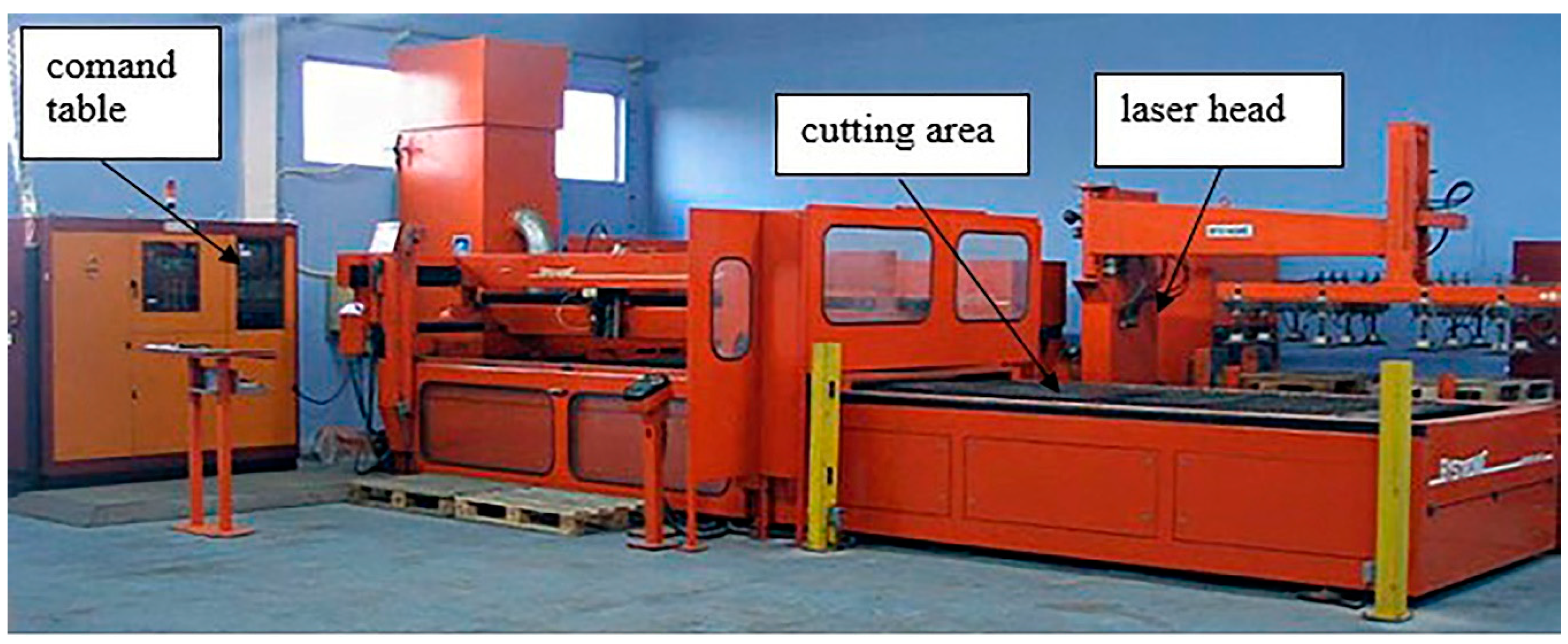
Laser cutting processing has been employed for different materials, such as steel [7], aluminum‒copper alloys [8], the 2024 aluminum alloy [9], phosphorous bronze [10], etc. Yilbas et al. [11] reported the laser cutting of titanium alloy, 304 steel, nickel-based superalloy Inconel 625, and an aluminum alloy, as well as the effect of laser power and cutting speed on the kerf width size. According to these authors, an increment in laser power and decrement in cutting speed generate an increased percentage of the kerf width size.
Kim et al. [12] presented the numerical model of laser cutting and showed that the setting of cutting parameters influences the cut quality of stainless steel. Hascalik and Ay [13] experimentally investigated the laser cut quality for the nickel superalloy, using a CO2 laser. Tadavani et al. [14] reported that the laser cutting of the Inconel 718b superalloy improved the surface quality by 22%, in comparison to conventional machining. The interdependences between the Nd:YAG laser cutting control factors and the surface roughness and kerf geometry were investigated for the alloy Al 6061T6 [15]. The same responses were also analyzed for the pulsed CO2 laser cutting in processing the composite material Al6061/Al2O3 [16]. Sharma and Yadava [17] showed that the use of oxygen as the assisting gas in the laser cutting of a nickel alloy could promote a smooth cut surface.
Tamilarasan and Rajamani [18] optimized the cutting parameters of Ti alloy samples and achieved a relative error of less than 2%. Pandey and Dubey [19] used pulsed Nd:YAG laser to cut the titanium alloy and showed that lower pulse width and pulse frequency and higher cutting speed result in a better cut. Texidor et al. [20] investigated the laser microcutting, and Savriama et al. [21] explained the novel pattering effects during the high-frequency laser microcutting of hard ceramics. Jarosz et al. [22] presented effect of the cutting speed on the surface roughness and HAZ of stainless steel, while the other control factors were kept constant. The effect of process factors on the kerf width and HAZ formation was analyzed for ultrahigh-strength steel by Tahir and Aqida [23]. Anicic et al. [24] demonstrated the ELM approach to predicting HAZ, taking into account the laser power, cutting speed, and pressure of the assisting gas.
Prashant et al. [25] presented an experimental study of Inconel 718 laser cutting. They investigated the parameter effects on the kerf deviation, and showed an improvement of 50% as a result of the optimized parameters in comparison to the initial parameters. Riviero et al. [26] investigated the optimal CO2 laser cutting settings for an aluminum–copper alloy (2024-T3).
Several studies have been conducted on the identification of laser cutting parameters that meet the requirements for multiple responses, but they mainly considered a very small number of responses (typically, only two). Tahir and Aqida [23] optimized the three laser cutting parameters (laser power, duty cycle, and cutting speed) aiming to decrease the HAZ and kerf width, using the response surface methodology (RSM). Although RSM is still one of the most frequently used approaches, it has several shortcomings: it does not address the response variability; the interdependences between responses are not addressed; and for nonlinear processes with multiple control factors and responses, it can converge to a local optimum, as mentioned by various authors [6]. A combination of Taguchi design and fuzzy logic in designing the laser cutting parameters for Duralumin sheets [27] was proposed, concerning the kerf width and deviation. In processing a Ni-based superalloy, the combination of Taguchi method and principal component analysis (PCA) was utilized to design the Nd:YAG laser cutting factors with respect to kerf width, deviation, and taper [28]. For the same material, laser, objectives, and process parameters, optimization of the laser cutting was performed using the conventional Taguchi method, i.e., the signal to noise ratio (SNR), and trade-offs were resolved by finding an accommodating solution [29]. Alizadeh and Omrani [30] optimized the CO2 laser cutting parameters using a combination of Taguchi method, back-propagation neural networks, and robust data envelopment analysis, aiming to decrease the kerf width and taper. For thermoplastics, Tamrin et al. [31] designed the major CO2 laser cutting parameters, employing a gray relational analysis (GRA) and aiming to reduce HAZ and improve the cut precision. In the Al alloy cutting, the control factors of the pulsed Nd:YAG laser-based process were designed with respect to the kerf taper and deviation. The process was mapped using the combination of Taguchi method and RSM and then optimized employing an integrated GRA‒entropy measurement method [32].
However, in the above six studies, only the discrete individual values used in the experiment were considered, so these approaches are not suitable for a global optimization that implies an investigation of the continuous space. Adalarasan [33] designed the parameters of a noncontact pulsed CO2 laser cutting in processing metal matrix composites, aiming to achieve the required values for the cut edge slope and surface finish. A combination of the Taguchi method, GRA, RSM, and desirability function analysis (DFA) was proposed to optimize the parameters of the process. Venkatesan and Ramanujam [34] investigated the control factors of laser-assisted machining in Inconel 718 processing. ANOVA results and regression modeling presented an input for DFA, aiming to minimize the cutting forces and achieve the desired value for workpiece temperature. However, in the case of correlated responses, both approaches are unsuitable due to a major drawback of the DFA-based methods: they neither address the response correlation problem nor exploit the response correlation information [35]. In one of the recent investigations of pulsed Nd:YAG laser cutting, the cutting speed, pulse energy, and pulse width were studied in order to increase MRR and reduce the surface roughness [36]. The development of the process model was done by ANNs, and the process parameters were optimized by a nondominated sorting GA (NSGAII). Similarly, Pandey and Kumar Dubey [19] optimized the laser cutting parameters (assisted gas pressure, pulse duration, pulse frequency, and cutting speed) to reduce the kerf taper and surface roughness. The response regression models served as objective functions for the Pareto front-based GA. Both methods are based on the Pareto front; therefore, they are not appropriate for problems with a large number of responses (more than three), since that would require trade-offs.
Therefore, the existing studies on laser cutting addressed only some of the major technological aspects, considering only a smaller part of the cut characteristics. Moreover, the optimization approaches used in these studies have certain shortcomings, as explained above, that could affect the efficiency of the obtained solutions.
There are various approaches for multiresponse optimization from the literature. Many of the statistical approaches are based on the Taguchi robust design and its combination with other statistical or artificial intelligence techniques. A detailed analysis of multiresponse optimization methods is presented in Sibalija and Majstorovic [6]. In general, the major shortcomings of many statistical methods in solving multiresponse problems are the subjectivity in assigning the relative response weights, and the inability to perform global optimization in a continual solution space.
As commented on by several authors, evolutionary optimization techniques present a very good alternative to statistical methods in optimizing machining processes. The genetic algorithm (GA) is the most frequently used metaheuristic in process optimizations. For instance, a combination of artificial neural networks (ANNs) and GA was applied to design the parameters of the profile extrusion process, considering a single response [37].
The PSO algorithm has recently been used for process optimization. There are a few PSO-based approaches developed to optimize single-response processes—e.g., Singh et al. [38] optimized a multimodal laser shock peening process considering a single response and multiple constraints. The other applications refer to problems where the analytical process model is known, such as PSO implementation for face milling optimization based on the known objective function [39]. Therefore, these approaches are limited in terms of their applicability in the optimization of diverse processes with unknown analytical models.
In some instances, PSO was combined with ANNs and the other optimization techniques. Katherasan et al. [40] modeled and optimized arc welding considering three objectives and using ANNs and PSO. In optimizing the ball-end milling parameters for two responses, GRA was applied to integrate responses, ANN performed process modeling, and PSO found the optimal process parameter settings [41]. In the above studies, some of the PSO specific parameters were reported, but the effect of their tuning on the PSO result was not studied. Moreover, the correlations among responses were not explicitly addressed.
The multi-objective PSO (MOPSO), based on Pareto front optimization, has also been applied to optimize processes with fewer responses. Mohanty et al. [42] used MOPSO to optimize the electrical discharge machining, where the Pareto solutions are presented for two responses. Based on the ANN response model, MOPSO was employed for high-speed milling optimization, considering two responses with equal weights [43]. However, the assignment of the weights was completely subjective, which could affect the overall analysis. Moreover, although Pareto front-based optimization has been successfully applied in optimizing problems with two objectives, its application is unsuitable for more than three responses due to the dimensional, dependent nature of this method and the need for trade-offs.
A detailed review and critical analysis of the PSO application in optimizing manufacturing processes, including laser-based processes, is presented in [44].
Previous studies showed that metaheuristic algorithm-specific parameters should be accurately set to ensure a fast convergence to the actual global optimum [6,44], but this issue has rarely been studied. Moreover, most of the methods mentioned are problem-dependent, so their applicability for optimizing other processes cannot be guaranteed.
Aiming to address the deficiencies of the above methods, an advanced PSO-based approach is employed to optimize the laser cutting parameters to fulfill the demands for multiple correlated responses of the Nimonic 263 cut.

3. Experiments

Superalloy Nimonic 263 sheets, 2 mm in thickness, were cut by a Bystronic laser, (2000), BYSTAR 3015 CNC Laser cutting machine (Bystronic Laser AG, Niederönz, Switzerland) (Figure 1). Table 1 gives the material chemical composition and Table 2 presents the laser specification.
Nitrogen (purity 99.998%) is used as the assisting gas, with nozzle diameter of 2 mm, nozzle type HK 20, and a focus distance of 190.5 mm.
The process parameters considered as control factors are the laser power, the pressure of the assisting gas (nitrogen), the focus position, and the cutting speed.
The resulting structural changes of a treated material are investigated by light microscopy. A detailed analysis is performed by scanning electron microscopy JEOL JSM-5800, (JEOL Ltd., Tokyo, Japan). Energy-dispersive spectroscopy (EDS) is used for the surface elemental analysis. A noncontact optical profiler Zygo NewView 7100 (Lambda Photometric Ltd., Hertfordshire, United Kingdom) is utilized for the determination of the surface characteristics and topography.
The number of responses is identified for the optimization: kerf taper (Kt), kerf deviation (Kd), microhardness (HV), the existence of solidified drops, i.e., grate (G), the surface roughness (Ra) and its root mean square value (Rms), and peak-to-valley values (PV). Microhardness measurements are performed by Vickers under a load of 9.81 N and a contact time of 10 s; tests are performed at three points and the average value is taken.
Table 3 lists the response specifications in terms of the signal to noise ratio (SNR) analysis: for all responses, except HV, it is desirable to achieve a minimal value (the smaller the better); for the response HV, large values are desired (the larger the better).
Table 4 lists the specifications for the process control factors and values used in the experiment. The experimental plan is based on the L9 matrix. To collect enough data for accurate process modeling, nine trials are repeated, so 18 trials are conducted in total (Table 5). For each of the 18 trials, three runs are performed, i.e., three workpieces are cut, and the response values are measured. Based on these measurements, the response mean is calculated (presented in Table 5), along with the standard deviation and quality loss (QL) function.

4. Methodology for the Process Parameters’ Design

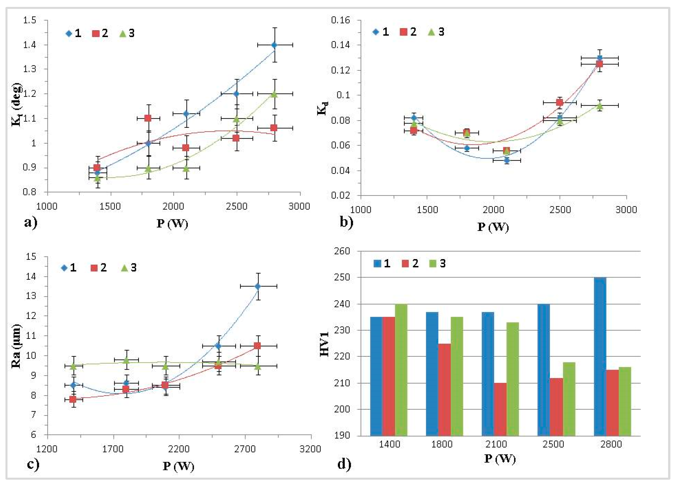
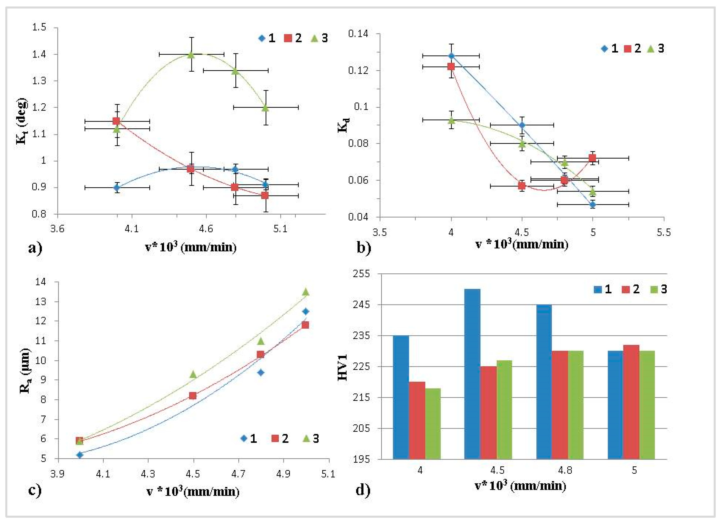
4.1. Analysis of Experimental Results

Analysis of variance (ANOVA) was conducted to determine the statistical significance of the cutting parameters for the observed responses, with a 0.05 significance level. It gave the following results.
-
For the responses Ra, Rms, and PV, all four process parameters are significant.
-
For the response Kd, the following process parameters are significant: Np, p, and v.
-
For the response Kt, the following parameters are significant: f, p, and v.
-
For the response HV, only parameter f is significant.
-
For the response G, the following parameters are significant: Np, f, and p.
The summary of ANOVA results with respect to the process parameters is as follows:
-
Parameter f is significant for all responses except for Kd;
-
Parameter P is significant for all responses except for HV;
-
Parameter Np is significant for all response except for Kt and HV;
-
Parameter v is significant for all responses except for HV and G.
Since all four cutting parameters (considered as process control factors) are significant for the majority of the responses, all of them are taken into account in the data processing, modeling, and optimization that follow.
Taguchi’s quality loss (QL) function is used to address the responses’ significance, in terms of the user dissatisfaction due to a response deviation from the requirement. It simultaneously takes into account both the response average and variability, as follows:
Q L = K { 1 n i = 1 n y i 2 s m a l l e r t h e b e t t e r   ( S T B ) 1 n i = 1 n ( y i m ) 2 = n 1 n s 2 + ( y ¯ m ) 2 n o m i n a l t h e b e s t   ( N T B ) 1 n i = 1 n 1 y i 2 l a r g e r t h e b e t t e r   ( L T B ) ,
where s2 and y ¯ are the variation and mean of the n sample size, respectively.
QL values are calculated for the sample of three measurements, and then normalized ( N Q L i ( k ) ϵ [ 0 ; 1 ] ).
PCA is applied over NQL to obtain the uncorrelated components (PCs) from the correlated data:
Y j ( k ) = i = 1 p NQL i ( k ) · V i j .
The calculation of Yj (k) values (Table 4) included all PCs, in order to capture the total response variability.
GRA is applied over Yj (k) to integrate the independent PCs. The computation of the gray relational grade uses the normalized Yj (k) values, i.e., Zi (k), and the weights ω j (the percentage of variance of PCj):
γ k = ω j · m i n j m i n k | Z j ( k ) 1 | + ζ m a x j m a x k | Z j ( k ) 1 | | Z j ( k ) 1 | + ζ m a x j m a x k | Z j ( k ) 1 | .
Hence, a single process measure ( γ k ϵ [ 0 ; 1 ] ) is developed in a fully objective manner since responses are expressed using QL, and it encompasses the total variability of the measured responses [6].

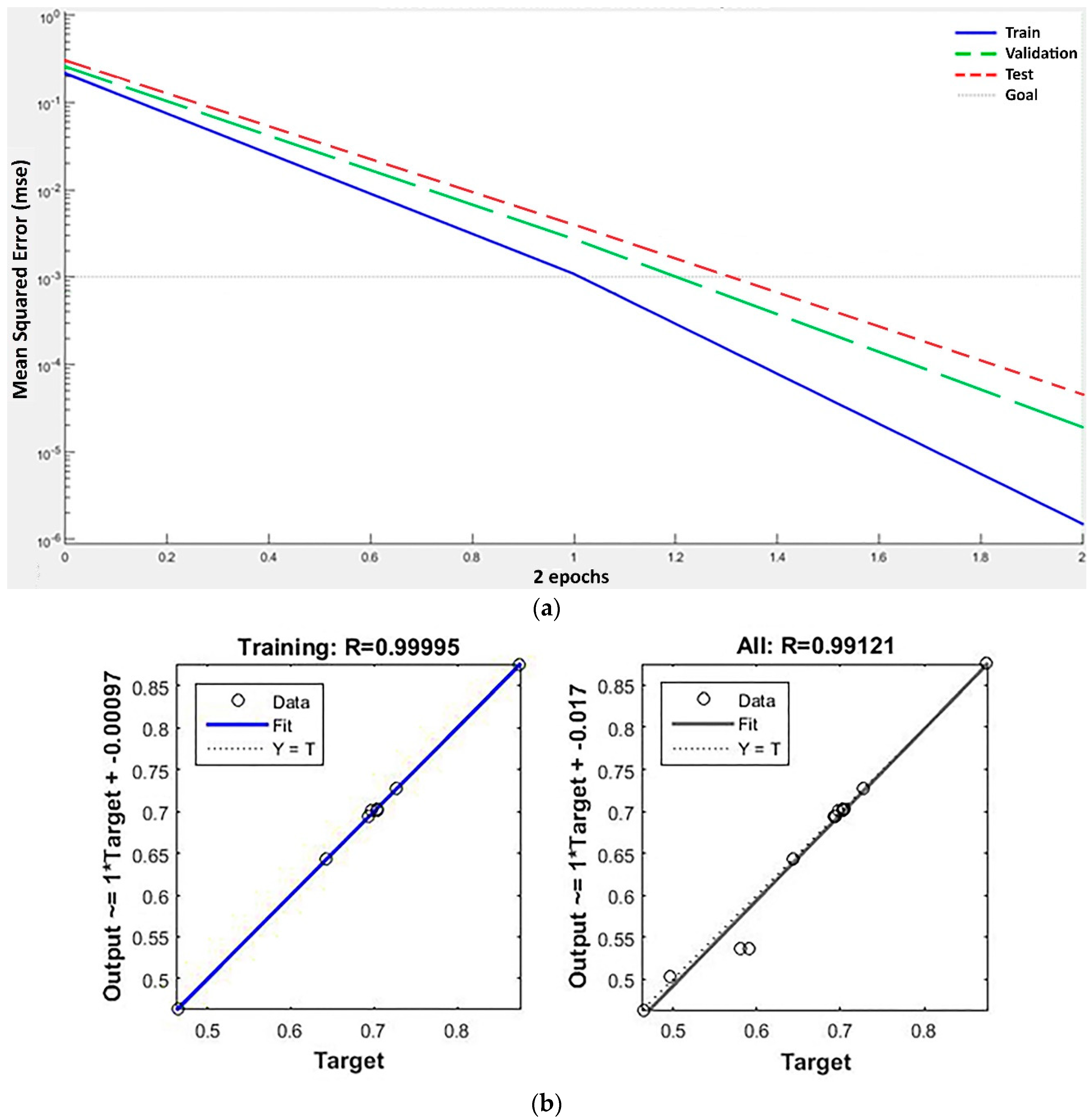
4.2. Process Modeling

The back-propagation (BP) ANNs with the Levenberg–Marquardt algorithm are used to map the input‒output process dependencies. The ANN with one hidden layer is adopted and the number of neurons (z) is varied, so the general ANN topology is 4-z-1. Relying on the proven effectiveness in modeling various processes, feed-forward ANNs with the tangent sigmoid and linear function, for the hidden and output layer, respectively, are utilized.
During the training process, first the training pattern is fed forward, the error is calculated and back-propagated, and then the weights are regulated. The randomly generated sets from the input‒output pairs are used for the gradient calculation as well as for weights and biases renewal. The overfitting avoidance is checked, and the network generalization is verified. The terminating criterion is to obtain a mean square error (MSE) lower than 0.001 or to complete 1000 iterations, whichever happens first.
Table 6 presents the training results of ANNs with different topologies, where MSE and the correlation coefficient (R) are used to evaluate and select the model. In total, 54 input‒output data pairs are used to develop ANNs, since the experiment included 18 trials and each trial included three workpiece measurements. As seen from Table 6, the obtained MSE values are on the order of 10−5–10−6, which is highly satisfactorily. Furthermore, the R values are in the range 0.99‒1.0 for all data and 0.97‒0.99 for the training dataset, which demonstrates a high correlation between the original data and the network output data. Therefore, ANNs accurately map the relationship between the process parameters and the process measure in the presented optimization methodology. This is mainly due to the adequate data preprocessing, since ANNs are trained using a process measure that is based on the set of normalized and standardized sequences integrated in a fully objective manner, rather than using noisy, row response data from the experiment. In addition, the network training parameters were carefully tuned: a low learning rate (0.01) and a high momentum (factor 0.9) were adopted to minimize the probability that the weights will be selected according to a local minimum, as proven effective in similar optimization problems [6].
The network 4-17-1 was adopted as the best one, since it obtained the smallest MSE of 1.5 × 10⁻⁶ and the highest R value: R = 1 for the training pairs; R = 0.99 for all input‒output pairs (Figure 2). Along with a low MSE for the training dataset, it is evident that the validation and test graphs follow the train graph pattern, reaching a highly satisfactory MSE on the order of 10−5 and demonstrating the very good generalization capability of the network.

4.3. Process Optimization

In our previous research, GA and SA were used as the optimization algorithms. Their comparison showed a favorable performance of SA in a vast majority of studies. Therefore, in our next work the SA-based approach was efficiently applied to optimize the laser shot peening process [45]. To further improve the methodology, in this study PSO is selected and compared to SA.

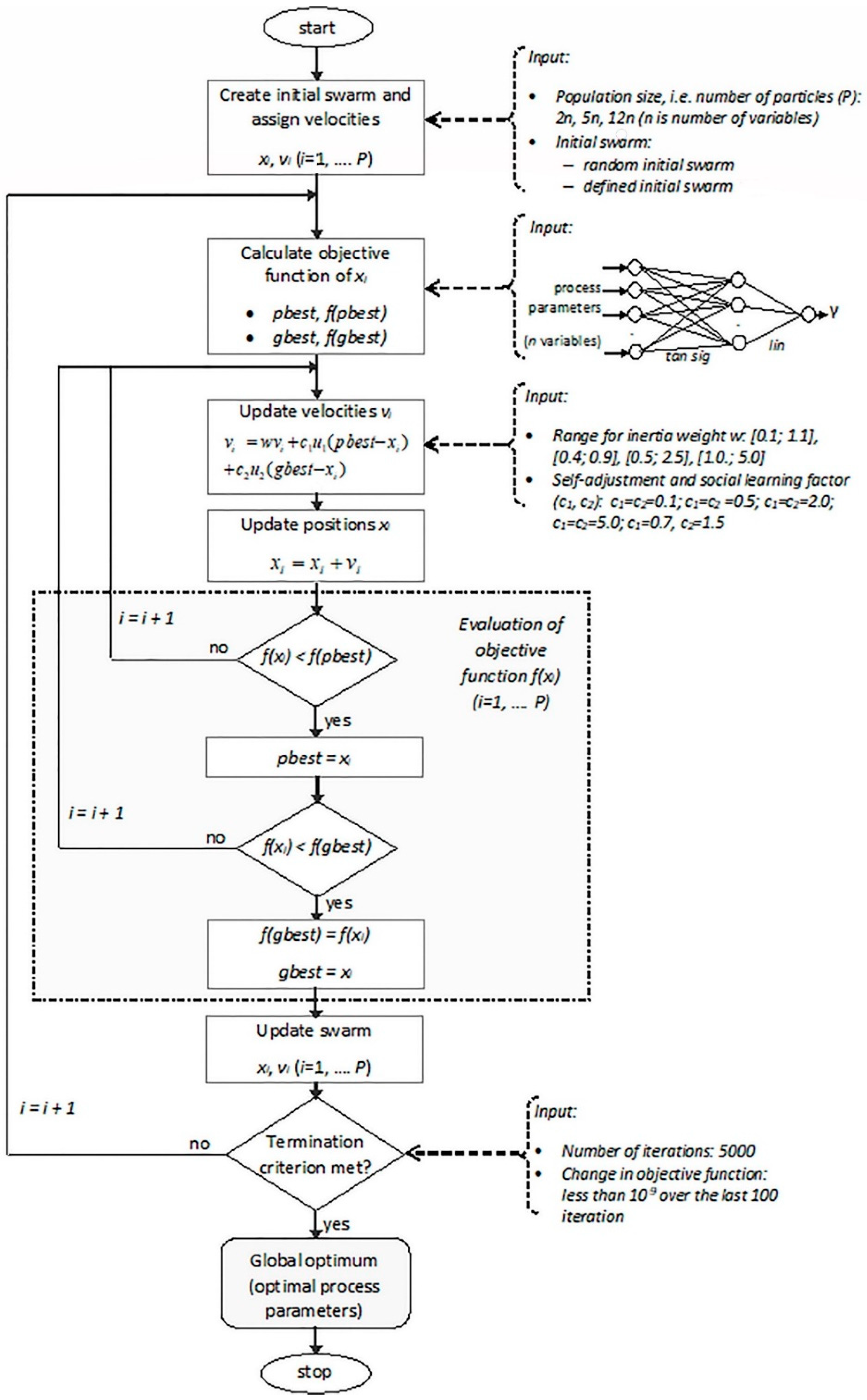
4.3.1. PSO-Based Process Optimization

PSO is an evolutionary algorithm that imitates insects’ swarming behavior, mimicking the movement of a set of particles (swarm) through a multidimensional space to attain the most desirable position. The particle movement is based on the best position reached so far, but also on the best position that any particle in a swarm reached so far.
The following lines depict the PSO procedure:
1. Create an initial swarm of P particles whose positions are xi (i = 1, …. P), and assign initial velocities vi.
2. Determine the objective function at each particle position xi in the swarm, in order to find: (i) the best particle position so far pbest (i.e., particle best), and the corresponding objective f (pbest); (ii) the best swarm position gbest (i.e., global best), and the corresponding objective f (gbest).
3. Update the velocities using: (i) the previous velocity vi, (ii) the particle cognition expressed via difference between the best and the current particle position (pbest − xi), and (iii) the social component expressed via difference between the swarm best position and the particle current position (gbest − xi):
v i = w v i + c 1 u 1 ( p b e s t x i ) + c 2 u 2 ( g b e s t x i ) ,
where w is the inertia weight, c1 and c2 are the self-adjustment and social adjustment learning factors, respectively, and u1 and u2 are random vectors (with lengths that coincide with the variable number).
4. Update the positions of particles, where the new location depends on the old one and on the velocity:
x i = x i + v i ,
and, if needed, enforce the limits to keep particles within the specified area.
5. Evaluate the objective function at all particles:
If f (xi) < f (pbest), set pbest = xi, to assure the particle best position;
If f (xi) < f (gbest), set f (gbest) = f (xi) and gbest = xi, to assure the best swarm position.
6. Update the swarm and go to step 2.
7. Repeat steps 2 to 6 until the algorithm arrives at the termination criterion.
It is important to note that, in Matlab (The MathWorks, Inc., Natick, MA, USA), during the evaluation of the objective function, the best function value refers to the lowest function value found in a swarm, and its location is adopted as the best location.
In contrast to other population-based algorithms, PSO relays on both local and global searching based on the best particle position (pbest) and the best swarm position (gbest). The particles fly with random velocities until all of them change positions once to complete one iteration, which is repeated until a stopping criterion is met.
As reported by several authors [44,46], the PSO parameters must be properly tuned to retain an equilibrium between global and local exploration and to find the actual optimum.
-
The initial swarm: While a majority of studies use a random initial swarm, it has been proven that the benefits of initializing particles to good positions could be significant [46]. However, some authors claim that, in contrast to the other metaheuristic methods, the initial swarm does not significantly affect the PSO accuracy. In this study, two options are tested: (a) a randomly generated initial swarm; (b) an initial swarm seeded in the vicinity of the solution that yielded the highest process measure in the experiment (Table 4).
-
The swarm size can take different values from 20 to 40, or up to 100 for very complex problems with a large number of variables. The proposed swarm size is 2n to 5n [47]; n is the number of process parameters in this case. It has been noted that a large swarm size significantly improves the success rate of the algorithm [44]. Since there are four cutting parameters analyzed in this study, the following swarm sizes are tested: 8, 20, and 50.
-
Inertia weight is used to restrict the particle velocity, since a particle could miss out on a good solution due to an excessively large velocity. This parameter has rarely been discussed in the literature. Pant [47] suggested the range [0.4; 0.9] for moderately sized problems with a number of variables from 2 to 20. The following inertia weight ranges are tested: [0.1; 1.1], [0.4; 0.9], [0.5; 2.5], and [1.0.; 5.0].
-
Typically, learning factors c1 and c2 are equal, and have values from 0 to 4. For moderately sized problems, it has been suggested to use c1 = c2 = 2.0 [47]. Since premature convergence is a major weakness of PSO, velocity reduction is recommended to improve the probability of obtaining a global optimum [44]. Therefore, the following values are tested: c1 = c2 = 0.1; c1 = c2 = 0.5; c1 = c2 = 2.0; c1 = c2 = 5, and c1 = 0.7, c2 = 1.5.
-
The algorithm termination usually refers to the specified number of iterations, which typically varies from a few hundred up to a few thousand. In this study, the algorithm terminates when it accomplishes 5000 iterations or when the objective function change over the last 100 iterations is less than 10−9, whichever is earlier.
Based on the results from Table 4, the maximal value for the parameter Np is increased to a small extent, so the observed problem is formulated as follows:
Maximize γ (Np; f; P; v)
Subject to
4 ≤ Np ≤ 14
1 ≤ f ≤ 3
1400 ≤ P ≤ 2800
4000 ≤ v ≤ 5000.
The values of the PSO parameters are varied to estimate their influence on the optimal solution. Therefore, 60 PSO algorithms are developed: 30 PSOs with a random initial swarm, and 30 PSOs with the defined initial swarm, as presented in Figure 3.
Table 7 lists the summary of the PSO results. PSO algorithms with a random initial swarm obtained γ values in the range 0.894012‒0.900825; 28 algorithms obtained a γ value of 0.900825, and two algorithms returned a lower value. The iteration number at which the best γ is reached is in the 30th‒70th iteration range. From 30 algorithms with the defined initial swarm, 29 algorithms obtained a γ value of 0.900825; the best γ was reached within 6‒30 iterations. Since almost all the algorithms found the same optimal solution, the algorithm with the fastest convergence was adopted as the best one. The best PSO algorithm converged to the optimum in the 6th iteration, using the following settings: swarm size = 8, inertia weight range = [0.1; 1.1], learning factors c1 = c2 = 5.
In general, PSO showed remarkable robustness as well as convergence speed. As was expected, algorithms with the defined initial swarm showed faster convergence than algorithms with a random initial swarm.

4.3.2. SA-Based Process Optimization

SA is a metaheuristic algorithm that imitates the metal heating process, where the temperature is increased to the melting condition and then gradually decreased to accomplish thermal stability. The annealing procedure commences at the starting point with a starting temperature supposed to be sufficiently high. Depending on the annealing function, a new point is selected close to the current one. If the new objective is inferior to the current one, the new point is taken to reduce the objective. The superior point could also be adopted, to enlarge the search and move away from a local solution. Then, the temperature is decreased.
In order to provide randomness within a search and avoid a local solution, especially in a high-temperature region, an appropriate temperature function should be chosen. In the last stage, the temperature is very low and there is little chance of adopting an inferior point, so the procedure is likely to reach an optimum [48].
Previous studies showed that the SA algorithm must be adequately tuned to generate the actual global optimum. The following recommendations, drawn from a previous analysis [6], are adopted:
-
The starting, i.e., initial point is placed near the best solution from the experiment.
-
Initial temperature values of 100 °C and 500 °C are tested.
-
The Boltzmann annealing function and fast annealing function are adopted for the annealing function.
-
For the temperature function, the Boltzmann and the fast temperature functions are tested.
-
The following combinations of reannealing interval and initial temperature are used: [10; 100], [10; 500], [100; 100], [100; 500].
-
The same termination condition as for PSO is used.
Using the same objective function as for PSO, 16 SA algorithms are run in Matlab (Table 6).
The γ values obtained by SA algorithms are in the range 0.890861‒0.900762, which is wider than the range obtained by PSOs, both with a random and with the defined initial swarm. The best γ obtained by SA is lower than the one obtained by PSO. The iteration number at which the best γ is found is in the range of 40‒1520 iterations, showing significantly slower convergence than PSO. This could be explained by the fact that SA performs a point-to-point search, while PSO searches the regions using a swarm.
The results of the PSO and SA applications in this study are summarized in Table 6. The best process measure γ obtained by PSOs is slightly higher than that obtained by SAs. The range of γ values obtained by SAs is larger than the range obtained by PSOs, indicating that PSO is more robust than SA. PSOs also had faster convergence than SAs. In summary, PSO outperformed SA in optimizing the laser cutting parameters, owing to its population-based nature and a combination of global and local searching. It is worth mentioning that PSOs with a defined initial swarm showed faster convergence than algorithms with a random initial swarm. However, PSOs with a random initial swarm also showed very fast convergence and excellent robustness.

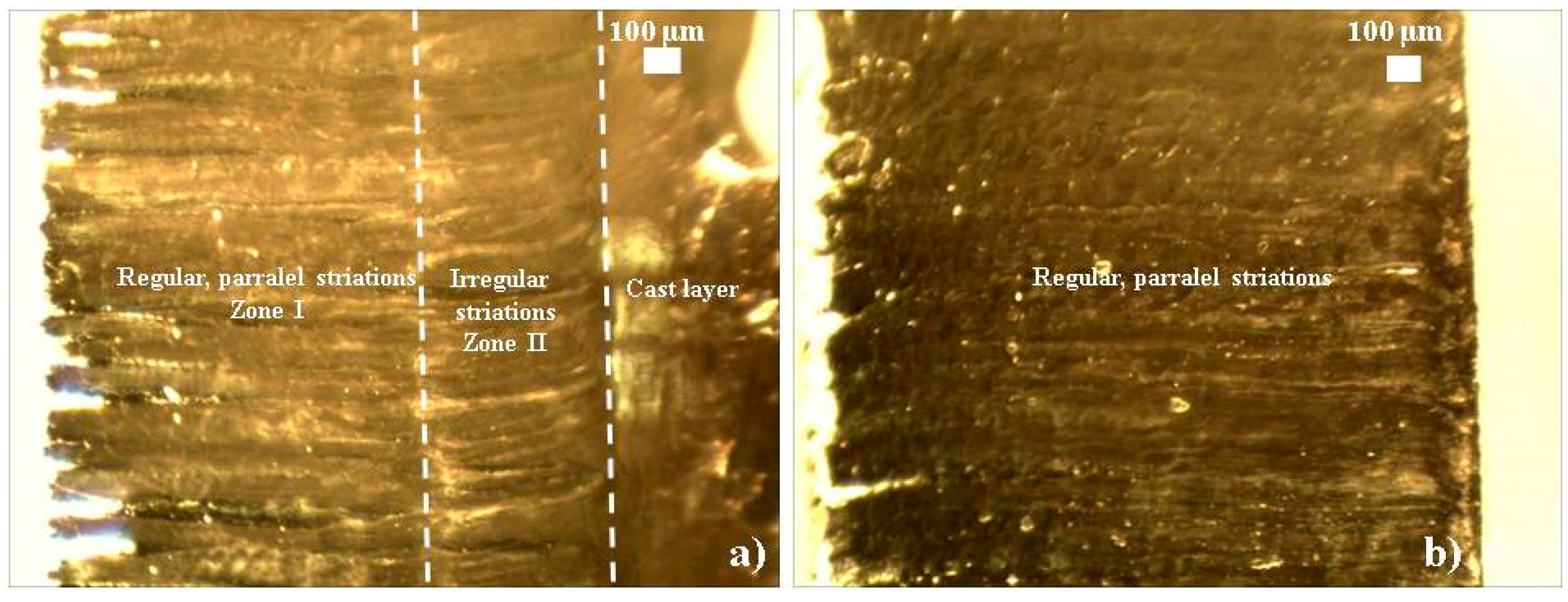
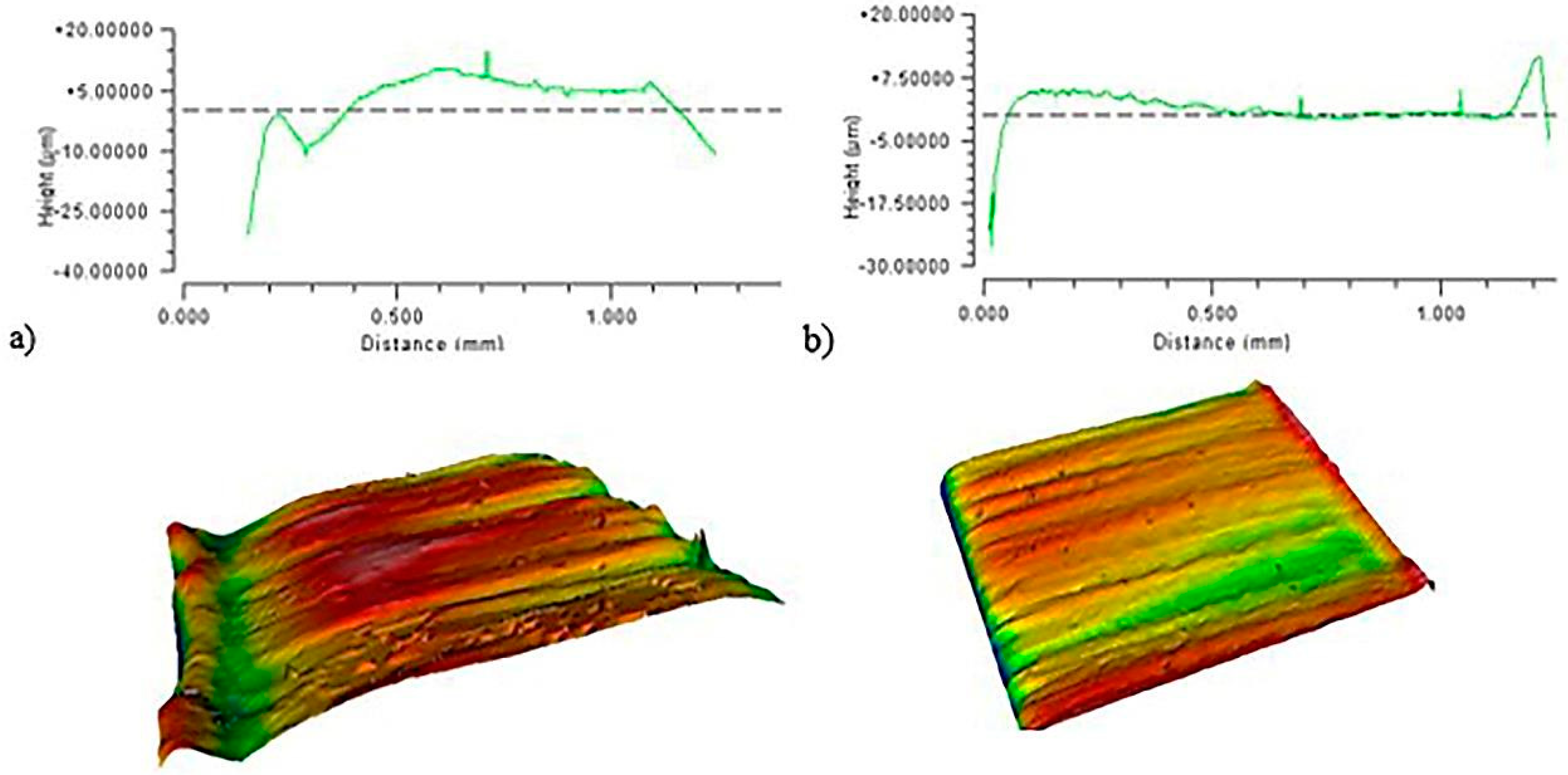
5. Experimental Validation and Discussion

The first part of this section examines the experimental data, i.e., the interdependences between process parameters and responses based on the row measured data. In the second part, the results of the implementation of the optimal parameter values obtained by PSO are scrutinized.
Figure 4 presents the nitrogen pressure effects on Kt (Figure 4a), Kd (Figure 4b), Ra (Figure 4c), and HV (Figure 4d) for three different focus positions. The laser power and cutting speed were kept constant: P = 2100 W; v = 4500 mm/min. According to the ANOVA results presented in Section 4.1, the parameter Np was not significant for the response Kt, for a significance level of 0.05. Figure 4a shows that there was no clear relationship between Kt and Np that would be valid for all three focus positions. Figure 4b shows that Kd increased with the nitrogen pressure increment. From Figure 4c it can be seen that Ra was reduced by increasing the value of Np, while there was no clear effect of the cutting parameters, except for focus position, on HV, which is in accordance with the ANOVA results (Figure 4d).
Figure 5 presents the laser power influence on Kt (Figure 5a), Kd (Figure 5b), Ra (Figure 5c), and HV (Figure 5d), considering three different focus positions. A lower laser power contributes to more regular striation patterns. This phenomenon is attributed to the lower amount of thermal energy delivered to the sheet per unit time during the cutting process. Additionally, the cut surfaces were more irregular, with higher Ra values due to the instability of the molten material along the cut front. There was no clear relationship between laser power and HV (Figure 5d), as confirmed by ANOVA.
Figure 6 presents the influence of the cutting speed on Kt (Figure 6a), Kd (Figure 6b), Ra (Figure 6c), and HV (Figure 6d), concerning three focus positions. It is clear that a higher cutting speed raised the total height of the roughness profile. A higher cutting speed caused the increased thickness of the molten material at the cut front area. The cut front geometry became corrugated, the resulting topography of the treated area was characterized by prominent peak and valleys. At lower cutting speed values, the striation patterns appeared more regular.
The solution found by the best PSO was adopted as the optimal laser cutting parameters in processing Nimonic 263 sheets, 2 mm thickness: Np = 14 bar; f = 0.5 mm in front of the material; P = 2034 kW; v = 4000 mm/min, since the obtained process measure value is highly satisfactory (γ = 0.900825). The experimental validation was performed using the above adopted setting; the microstructural characterization of the cut was studied and compared with a nonoptimized cut.
The cut appearance before and after optimization is given in Figure 7a,b, respectively.
Figure 7a shows the microstructure obtained by nonoptimized parameters: Np = 8 bar; f = on the bottom of a material; P = 2100 kW; v = 4000 mm/min. Areas with different topography characteristics can be distinguished on the treated surface. It is clear that a flow pattern of striations has two zones. Zone I (1.6 mm depth from the cut edge top) is smoother, with regular and parallel striations and an average width of 130 μm, and covers roughly 55 percent of the treated surface area. However, the striations become irregular and nonparallel, with no clear direction in zone II, taking up approximately 25 percent of the treated surface area. The formation of a cast layer at the cut surface arises due to a fast solidification of the melted metal, which occurs due to the effect of convection cooling produced by the high pressure of the nitrogen gas.
Figure 7b shows the surface structure after optimization, where striations (width 14‒28 μm) are almost parallel and straight along the whole cutting area. Almost no grate or adhered material is observed, and a uniformly treated surface area was obtained.
The cut responses Kd and Kt generated by the optimized parameters were 0.057 mm and 0.9 mm, respectively, and by a nonoptimized process they were 0.123 mm and 1.15 mm. The microhardness (HV) obtained by the optimized process was 235 HV1, presenting a clear advantage for the structure since the HV of a nonoptimized cut area is 219 HV1. The optimized parameters provide orderly structure, small kerf with parallel edges, high quality of the cut surface, and a minimum grate.
It is clear that Kd and Kt are reduced when there is an increase in the laser power, which is due to the mechanical force growth. Higher energy and mechanical force contribute to the elimination of deep grooves, which results in a better surface roughness.
For the parts requiring wear resistance, the removal of a roughened surface is mandatory to ensure better performance. A roughened peak could initiate a microcrack formation or a microcrack propagation due to the local stress generated on this part of a surface. The cut profiles were inspected by a noncontact profilometer.
Figure 8 presents 2D and 3D images of the cutting zones before and after optimization. The optimized laser cutting resulted in a more regular surface and more consistent structure than a nonoptimized process. The Ra values of the optimized and nonoptimized cuts were 5.2 μm and 10.5 μm, respectively. The roughness root mean squares (Rms) of the optimized and nonoptimized cuts were 6.3 μm and 11.7 μm, respectively. The PV ratio of the optimized cut was 106.6 μm, while that of a nonoptimized cut was 159.9 μm. The grate (G) phenomenon did not occur, neither beneath the treated area nor anywhere around the area. Hence, the observed responses were significantly improved by using the optimized laser cutting parameters; in particular, the kerf deviation improved by almost 200% in comparison with the experimental data.
The surface microstructure achieved by a nonoptimized process is characterized by a few microcracks and the beginning of the grain boundaries’ segregation (Figure 9a). The presented microstructure is susceptible to microcrack formation due to the concentrated local stress. A high thermal strain leads to microcracks at the kerf surface; they can proliferate if a high laser power or low cutting velocity is applied.
Figure 9b shows the homogeneous cut surface after optimization; there are no microcracks and the cut face is smooth. The laser interaction on the material caused the formation of twinned grains, visible in both images. The twinned grains are considered to support the microstructure as they increase the fatigue strength, hardness, and yield [49].
The laser cutting study of Nimonic 263 was successfully implemented in the metalworking factory in Bor, Serbia, as presented above. According to the chemical composition of a material, the obtained results can also be applied to the laser cutting of nickel-based superalloys and alloys with similar mechanical and metallurgical characteristics. The results of this study could serve as the basis for cutting process optimization in processing similar alloys with a similar thickness of workpiece.
The present study focused on process quality improvement in terms of the technological characteristics of the cut material. Future work could include also techno-economic optimization, involving the responses that address productivity and economic aspects such as the material removal rate. The application of the proposed optimization methodology can be extended to design cutting process parameters for different thicknesses of workpiece, more complex shapes, and different alloys.

6. Conclusions

Since a Nimonic 263 superalloy is classified as difficult to cut, laser cutting has emerged as a promising tool for processing. In this study, the laser cutting parameters optimized by the PSO-based approach significantly improved the quality of the Nimonic 263 cut area and the microstructure.
The main novelty of this study is the comprehensive and systematic experimental analysis of the major laser cutting parameters in processing a Ni-based superalloy; we simultaneously address four major technological aspects: the kerf geometry, the surface roughness aspect, the existence of solidified drops (grate), and the microhardness. This presents a clear advance in comparison to existing optimization studies on the laser cutting of similar materials, since they included only a small number of cut characteristics (mainly, kerf geometry and surface roughness), hence addressing only some of the technological aspects.
After the experimental data processing, a well-trained neural process model (R = 1; MSE = 1.5 10−6) was developed and fed into PSO to predict the optimal laser cutting parameters based on the requirements for seven responses. PSO showed a remarkable robustness and very fast convergence. The predicted performance of the optimal laser cutting by PSO was verified in the verification run, obtaining the following response values: Kd = 0.057 mm, Kt = 0.9 mm; HV = 235 HV1; G = 0 (grate did not occur); Ra = 5.2 μm; Rms = 6.3 μm; PV = 106.6 μm; the actual obtained performance value was γ = 0.899612, which is very close to the value predicted by PSO γ = 0.900825. This confirms the effectiveness of the proposed PSO-based method in optimizing laser cutting parameters. Therefore, the obtained results are implemented in the laser cutting of demanding functional parts made of Nimonic 263, which operates in harsh conditions.
The optimized microstructure was more uniform. The cut surface was smooth and microcrack-free; the roughness and peak to valley ratio was reduced, as well as the kerf deviation and kerf taper. The grate phenomenon did not occur and the microhardness was increased. These findings could be useful in several industrial sectors, such as gas and steam turbines, heat exchangers, power plant production, and, in particular, aircraft engine production since this sector requires high-quality responses and very tight tolerances.
The proposed PSO-based approach was successful in optimizing a complex process with multiple process parameters and multiple correlated responses, showing its appropriateness for use in industrial practice. The improvement and advances of the optimization methodology were clearly demonstrated, in terms of PSO usage instead of SA. Moreover, the shortcomings of the existing approaches used to optimize laser-based processes were overcome, since the proposed approach successfully deals with a large number of responses, addressing their correlations and multiple conflicting objectives without any trade-offs, and performing a global optimization in a continual space.
Future research will include the processing of thicker materials, different alloys, and shapes that are more complex.

Author Contributions

Conceptualization, T.S. and S.P.; methodology, T.S. and S.P.; software, T.S.; validation, T.S. and S.P.; formal analysis, T.S., S.P. and D.M.; investigation, S.P. and D.M.; data curation, T.S.; writing—original draft preparation, T.S. and S.P.; writing—review and editing, T.S., S.P. and D.M.

Funding

This research was partly funded by the Ministry of Education, Science and Technological Development of the Republic of Serbia.

Acknowledgments

This research was partly supported by the Ministry of Education, Science and Technological Development of the Republic of Serbia under contract numbers TR 35040, TR 37021, and OI 172045.

Conflicts of Interest

The authors declare no conflict of interest.

References

  1. De Oliveira, M.M.; Couto, A.A.; Almeida, G.F.C.; Reis, D.A.P.; de Lima, N.B.; Baldan, R. Mechanical Behavior of Inconel 625 at Elevated Temperatures. Metals 2019, 9, 301. [Google Scholar] [CrossRef]
  2. Petronic, S.; Sibalija, T.; Burzic, M.; Polic, S.; Colic, K.; Milovanovic, D. Picosecond Laser Shock Peening of Nimonic 263 at 1064 nm and 532 nm Wavelength. Metals 2016, 6, 41. [Google Scholar] [CrossRef]
  3. Kondaya, D.; Krishna, A.G. An integrated evolutionary approach for modelling and optimization of laser beam cutting process. Int. J. Adv. Manuf. Technol. 2013, 65, 259–274. [Google Scholar] [CrossRef]
  4. Petru, J.; Zlamal, T.; Cep, R.; Monkova, K.; Monka, P. Influence of Cutting Parameters on Heat-affected Zone After Laser Cutting. Tehnički Vjesnik 2013, 20, 225–230. [Google Scholar]
  5. Eltawahni, H.A.; Hagino, M.; Benyounis, K.Y.; Inoue, T.; Olabi, A.G. Effect of CO2 laser cutting process parameters on edge quality and operating cost of AISI316L. Opt. Laser Technol. 2012, 44, 1068–1082. [Google Scholar] [CrossRef]
  6. Sibalija, T.; Majstorovic, V. The Advanced Multiresponse Process. Optimisation: An Intelligent and Integrated Approach; Springer International Publishing: Cham, Switzerland, 2016. [Google Scholar]
  7. Russo Spena, P. CO2 Laser Cutting of Hot Stamping Boron Steel Sheets. Metals 2017, 7, 456. [Google Scholar] [CrossRef]
  8. Riveiro, A.; Quintero, F.; Lusquinos, F.; Comesaña, R.; Pou, J. Effects of processing parameters on laser cutting of aluminum–copper alloys using off-axial supersonic nozzles. Appl. Surf. Sci. 2011, 257, 5393–5397. [Google Scholar] [CrossRef]
  9. Reck, A.; Zeuner, A.T.; Zimmermann, M. Fatigue Behavior of Non-Optimized Laser-Cut Medical Grade Ti-6Al-4V-ELI Sheets and the Effects of Mechanical Post-Processing. Metals 2019, 9, 843. [Google Scholar] [CrossRef]
  10. Yilbas, B.S.; Ahktar, S.S.; Chatwin, C. Laser hole cutting into bronze: Thermal stress analysis. Opt. Laser Technol. 2011, 43, 1119–1127. [Google Scholar] [CrossRef]
  11. Yilbas, B.S.; Shaukat, M.M.; Ashraf, F. Laser cutting of various materials: Kerf width size analysis and life cycle assessment of cutting process. Opt. Laser Technol. 2017, 93, 67–73. [Google Scholar] [CrossRef]
  12. Kim, B.C.; Kim, T.H.; Jang, Y.S.; Chung, K.H. Investigation of striation formation in thin stainless steel tube during pulsed Nd: YAG laser cutting process by numerical simulation. Metall. Mater. Trans. A 2001, 32, 2623–2632. [Google Scholar] [CrossRef]
  13. Hascalık, A.; Ay, M. CO2 laser cut quality of Inconel 71 8 nickel–based superalloy. Opt. Laser Technol. 2013, 48, 554–564. [Google Scholar] [CrossRef]
  14. Tadavani, S.A.; Razavi, R.S.; Vafaei, R. Pulsed laser-assisted machining of Inconel 718 superalloy. Opt. Laser Technol. 2017, 87, 72–78. [Google Scholar] [CrossRef]
  15. Leone, C.; Genna, S.; Caggiano, A.; Tagliaferri, V.; Molitierno, R. Influence of process parameters on kerf geometry and surface roughness in Nd:YAG laser cutting of Al 6061T6 alloy sheet. Int. J. Adv. Manuf. Technol. 2016, 87, 2745–2762. [Google Scholar] [CrossRef]
  16. Adalarasan, R.; Santhanakumar, M.; Thileepan, S. Selection of optimal machining parameters in pulsed CO2 laser cutting of Al6061/Al2O3 composite using Taguchi-based response surface methodology (T-RSM). Int. J. Adv. Manuf. Technol. 2017, 93, 305–317. [Google Scholar] [CrossRef]
  17. Sharma, A.; Yadava, V. Optimization of cut quality characteristics during Nd: YAG laser straight cutting of Ni-based superalloy thin sheet using grey relational analysis with entropy measurement. Mater. Manuf. Process. 2011, 26, 1522–1529. [Google Scholar] [CrossRef]
  18. Tamilarasan, A.; Rajamani, D. Multi-response optimization of Nd: YAG laser cutting parameters of Ti-6Al-4V superalloy sheet. J. Mech. Sci. Technol. 2017, 31, 813–821. [Google Scholar] [CrossRef]
  19. Pandey, A.K.; Dubey, A.K. Simultaneous optimization of multiple quality characteristics in laser cutting of titanium alloy sheet. Opt. Laser Technol. 2012, 44, 1858–1865. [Google Scholar] [CrossRef]
  20. Teixidor, D.; Grzenda, M.; Bustillo, A.; Ciurana, J. Modeling pulsed laser micromachining of micro geometries using machine-learning techniques. J. Intell. Manuf. 2015, 26, 801–814. [Google Scholar] [CrossRef]
  21. Savriama, G.; Jarry, V.; Barreau, L.; Boulmer-Leborgn, C.; Semmar, N. A novel patterning effect during high frequency laser micro-cutting of hard ceramics for microelectronics applications. Appl. Surf. Sci. 2014, 302, 163–168. [Google Scholar] [CrossRef]
  22. Jarosz, K.; Löschner, P.; Niesłony, P. Effect of cutting speed on surface quality and heat-affected zone in laser cutting of 316L stainless steel. Procedia Eng. 2016, 149, 155–162. [Google Scholar] [CrossRef]
  23. Tahira, F.M.; Aqida, N.A. An investigation of laser cutting quality of 22MnB5 ultra high strength steel using response surface methodology. Opt. Laser Technol. 2017, 92, 142–149. [Google Scholar] [CrossRef] [Green Version]
  24. Anicic, O.; Jovic, S.; Skrijelj, H.; Nedic, B. Prediction of laser cutting heat affected zone by extreme learning machine. Opt. Lasers Eng. 2017, 88, 1–4. [Google Scholar] [CrossRef]
  25. Prashant, K.S.; Gavendra, N.; Pandey, A.K. Modelling and Optimization of Kerf Deviation in Laser Cutting of Inconel-718 Sheet. In Proceedings of the 6th International & 27th All India Manufacturing Technology, Design and Research Conference (AIMTDR-2016), Maharashtra, India, 16–18 December 2016; pp. 515–521. [Google Scholar]
  26. Riveiro, A.; Quintero, F.; Lusquiños, F.; Comesana, R.; Pou, J. Parametric investigation of CO2 laser cutting of 2024-T3 alloy. J. Mat. Process. Technol. 2010, 210, 1138–1152. [Google Scholar] [CrossRef]
  27. Pandey, A.K.; Dubey, A.K. Taguchi based fuzzy logic optimization of multiple quality characteristics in laser cutting of Duralumin sheet. Opt. Lasers Eng. 2012, 50, 328–335. [Google Scholar] [CrossRef]
  28. Dubey, A.K.; Yadava, V. Multi-objective optimization of Nd:YAG laser cutting of nickelbased superalloy sheet using orthogonal array with principal component analysis. Opt. Lasers Eng. 2008, 46, 124–132. [Google Scholar] [CrossRef]
  29. Sharma, A.; Yadava, V.; Rao, R. Optimization of kerf quality characteristics during Nd:YAG laser cutting of nickel based superalloy sheet for straightand curved cut profiles. Opt. Lasers Eng. 2010, 48, 915–925. [Google Scholar] [CrossRef]
  30. Alizadeh, A.; Omrani, H. An integrated multi response Taguchi-neural network-robust data envelopment analysis model for CO2 laser cutting. Measurement 2019, 131, 69–78. [Google Scholar] [CrossRef]
  31. Tamrin, K.F.; Nukman, Y.; Choudhury, I.A.; Shirley, S. Multiple-objective optimization inprecision laser cutting of different thermoplastics. Opt. Lasers Eng. 2015, 67, 57–65. [Google Scholar] [CrossRef]
  32. Sharma, A.; Yadava, V. Modelling and optimization of cut quality during pulsed Nd:YAG laser cutting of thin Al-alloy sheet for curved profile. Opt. Lasers Eng. 2013, 51, 77–88. [Google Scholar] [CrossRef]
  33. Adalarasan, R.; Santhanakumar, M.; Rajmohan, M. Optimization of laser cutting parameters for Al6061/SiCp/Al2O3 composite using grey based response surface methodology (GRSM). Measurement 2015, 73, 596–606. [Google Scholar] [CrossRef]
  34. Venkatesan, K.; Ramanujam, R. Statistical approach for optimization of influencing parameters in laser assisted machining (LAM) of Inconel alloy. Measurement 2016, 89, 97–108. [Google Scholar] [CrossRef]
  35. Murphy, T.E.; Tsui, K.L.; Allen, J.K. A review of robust design methods for multiple responses. Res. Eng. Des. 2005, 16, 118–132. [Google Scholar] [CrossRef]
  36. Chaki, S.; Bathe, R.N.; Ghosal, S.; Padmanabham, G. Multi-objective optimisation of pulsed Nd:YAG laser cutting process using integrated ANN–NSGAII model. J. Intell. Manuf. 2019, 29, 175–190. [Google Scholar] [CrossRef]
  37. Yan, H.; Xia, J. An approach to the optimal design of technological parameters in the profile extrusion process. Sci. Technol. Adv. Mater. 2006, 7, 127–131. [Google Scholar] [CrossRef]
  38. Singh, G.; Grandhi, R.V.; Stargel, D.S. Modified particle swarm optimization for a multimodal mixed-variable laser peening process. Struct. Multidis. Optim. 2010, 42, 769–782. [Google Scholar] [CrossRef]
  39. Bharathi Raja, S.; Baskar, N. Application of Particle Swarm Optimization technique for achieving desired milled surface roughness in minimum machining time. Expert Syst. Appl. 2012, 37, 878–885. [Google Scholar] [CrossRef]
  40. Katherasan, D.; Elias, J.V.; Sathiya, P. Simulation and parameter optimization of flux cored arc welding using artificial neural network and particle swarm optimization algorithm. J. Intell. Manuf. 2014, 25, 67–76. [Google Scholar] [CrossRef]
  41. Zhou, J.; Ren, J.; Yao, C. Optimisation of multi-axis ball-end milling in processing Inconel 718 was performed using a hybrid GRA-NN-PSO method. Measurement 2017, 102, 271–285. [Google Scholar] [CrossRef]
  42. Mohanty, C.P.; Mahapatra, S.S.; Singh, M.R. A particle swarm approach for multi-objective optimization of electrical discharge machining process. J. Intell. Manuf. 2016, 27, 1171–1190. [Google Scholar] [CrossRef]
  43. Escamilla-Salazar, I.G.; Torres-Treviño, L.M.; González-Ortíz, B.; Zambrano, C.P. Machining optimization using swarm intelligence in titanium (6Al 4V) alloy. Int. J. Adv. Manuf. Technol. 2013, 67, 535–544. [Google Scholar] [CrossRef]
  44. Sibalija, T. Particle Swarm Optimisation in Designing Parameters of Manufacturing Processes: A Review (2008–2018). Appl. Soft Comput. J. 2019, 84, 105743. [Google Scholar] [CrossRef]
  45. Sibalija, T.; Petronic, S.; Majstorovic, V.; Milosavljevic, A. Modelling and optimisation of laser shock peening using an integrated simulated annealing-based method. Int. J. Adv. Manuf. Technol. 2014, 73, 1141–1158. [Google Scholar] [CrossRef]
  46. Banks, A.; Vincent, J.; Anyakoha, C. A review of particle swarm optimization. Part I: Background and development. Nat. Comput. 2007, 6, 467–484. [Google Scholar] [CrossRef]
  47. Pant, M.; Thangaraj, R.; Abraham, A. Particle Swarm Optimization: Performance Tuning and Empirical Analysis. In Foundations of Computational Intelligence; Springer: Berlin/Heidelberg, Germany, 2009; Volume 3, pp. 101–128. [Google Scholar]
  48. Spall, J. Introduction to Stochastic Search and Optimisation; John Wiley & Sons, Inc.: Hoboken, NJ, USA, 2003. [Google Scholar]
  49. Ren, X.D.; Zhang, Y.K.; Zhang, T.; Jiang, D.W.; Yongzhuo, H.F.; Jiang, Y.F.; Chen, K.M. Comparison of the simulation and experimental fatigue crack behaviours in the nanosecond’s laser shocked aluminum alloy. Mat. Des. 2011, 32, 1138–1143. [Google Scholar] [CrossRef]
Figure 1. Laser cutting system BYSTAR 3015, 2.8 kW, with two tables 1500 × 3000 mm.
Metals 09 01147 g001
Figure 2. The selected neural model 4-17-1: (a) The network performance: MSE vs. iterations; (b) regression plots: the actual output vs. the targets for the training dataset (left) and for all data (right).
Metals 09 01147 g002
Figure 3. The PSO algorithm flowchart used in this study.
Metals 09 01147 g003
Figure 4. Cut quality vs. nitrogen pressure and focus position: (a) Kerf taper, (b) Kerf deviation, (c) average roughness, and (d) microhardness. 1—material top, 2—material bottom, 3—0.5 mm in front of material.
Metals 09 01147 g004
Figure 5. Cut quality vs. laser power and focus position: (a) Kerf taper, (b) Kerf deviation, (c) average roughness, and (d) microhardness. 1—material top, 2—material bottom, 3—0.5 mm in front of material.
Metals 09 01147 g005
Figure 6. Cut quality vs. cutting speed and focus position: (a) Kerf taper, (b) Kerf deviation, (c) average roughness, and (d) microhardness. 1—material top, 2—material bottom, 3—0.5 mm in front of material.
Metals 09 01147 g006
Figure 7. Appearance of the laser cut on Nimonic surface: (a) before optimization; (b) after optimization, taken by an optical microscope (magnification 30×).
Metals 09 01147 g007
Figure 8. 2D profile and 3D map of the cutting area obtained by: (a) nonoptimized parameters, (b) optimized parameters.
Metals 09 01147 g008
Figure 9. Microstructure of the cut material, shown by scanning electron microscopy: (a) before optimization; (b) after optimization. Bars in the upper left corner denote 50 μm.
Metals 09 01147 g009
Table 1. Nimonic 263 chemical composition (%).
ElementCSiMnAlCoCrCuFeMoTiNi
%0.060.300.500.5020.0020.000.100.505.902.2049.94
Table 2. Bystronic laser, (2000), BYSTAR specification.
Laser Beam Power2800 W
Polarizationcircular
Speed6000 mm/min
Pulse Frequency2500 Hz
Assisting GasNitrogen
Pressure of Assisting Gas20 bar
Table 3. Response specifications.
ResponsesUnitSymbolRequired ValueResponse Type in SNR Analysis
Kerf deviationmmKdMinimal valueSTB
Kerf tapper°KtMinimal valueSTB
MicrohardnessHV1HVMaximal valueLTB
Grate -GMinimal valueSTB
Roughness µmRaMinimal valueSTB
Roughness root mean squareµmRmsMinimal valueSTB
Roughness peak-to-valley-PVMinimal valueSTB
Table 4. Process parameters’ specification.
Process ParametersUnitSymbolLevels
123
Nitrogen pressurebarNp4812
Focus position-f1
(on the top of the material)
2
(on the bottom of the material)
3
(0.5 mm in front of the material)
Laser powerWP140021002800
Cutting speedmm/minv400045005000
Table 5. Part of experimental plan, response values, principal components Yj (k), and gray relational grades γk.
No.Parameter LevelsResponsesPrincipal Component Scores Yj(k) (j = 1, … 7; k = 1, … 18)γk (k = 1, … 18)
NpfPvKdKtHVGRaRmsPVY1(k)Y2(k)Y3(k)Y4(k)Y5(k)Y6(k)Y7(k)
111110.0631.13235.208.510.7104.90.51−0.57−0.310.040.240.06−0.110.6974
212220.0570.97209.708.610.7106.30.25−0.80−0.65−0.400.22−0.20−0.090.6932
313330.0771.20219.409.511.4190.60.75−0.38−0.82−0.460.610.09−0.150.5799
421230.0470.90236.315.97.4159.60.52−0.110.38−0.760.57−0.18−0.100.7042
522310.1231.15219.6110.511.8158.11.33−1.14−0.11−1.090.170.10−0.130.4965
623120.0930.87240.609.512.0209.70.830.11−0.68−0.450.290.11−0.050.6427
731320.1271.40251.5113.418.4183.12.26−0.79−0.08−0.480.29−0.06−0.120.4641
832130.0730.57234.905.911.0198.50.360.25−0.57−0.520.23−0.05−0.200.7272
933210.0570.90230.405.26.3106.60.07−0.40−0.22−0.160.180.09−0.150.8744
1833210.0580.91231.005.36.3107.00.09−0.40−0.22−0.150.180.10−0.140.8672
Table 6. Results of ANNs training: MSE and R values for the training data and for all data.
ANN Topology4-10-14-12-14-15-14-16-14-17-14-18-14-20-1
MSE2.68 × 10−54.22 × 10−63.48 × 10−61.85 × 10−61.51 × 10−68.45 × 10−61.32 × 10−5
R for training data0.970.970.980.980.990.990.98
R for all data0.990.991.001.001.001.001.00
Table 7. Summary of the results of PSO and SA application with different algorithm-specific parameter settings.
Optimization AlgorithmPSO with a Random Initial PopulationPSO with a Defined Initial PopulationSA
The range of the obtained process measure γ 0.894012 ÷ 0.9008250.893701 ÷ 0.9008250.890861 ÷ 0.900762
The best process measure γ0.9008250.9008250.900762
The optimal process parameters setting that corresponds
to the best γ
[14; 3; 2034; 4000][14; 3; 2034; 4000][14; 3; 2039; 4000]
The number of iterations at which the best process measure is reached30 ÷ 706 ÷ 3040 ÷ 1520
The total number of iterations performed by the algorithm121 ÷ 341105 ÷ 2912027 ÷ 3530

