Article

Role of Substrates in the Corrosion Behaviors of Micro-Arc Oxidation Coatings on Magnesium Alloys

1
College of Materials Science and Engineering, Nanjing Tech University, Nanjing 211816, China
2
College of Materials Science and Engineering, Xi’an University of Technology, Xi’an 710048, China
*
Author to whom correspondence should be addressed.
Metals 2019, 9(10), 1100; https://doi.org/10.3390/met9101100
Submission received: 20 September 2019 / Revised: 9 October 2019 / Accepted: 10 October 2019 / Published: 14 October 2019

Abstract

:
Micro-arc oxidation (MAO) was performed on AZ31 and AZ91 Mg alloys to explore the relationship between Mg substrates and corrosion behaviors of resultant coatings. The microstructure and long-term corrosion performance of the two coatings were investigated. Results showed that MAO coating on AZ91 alloy provided a longer-term corrosion protection to substrate than that on AZ31 alloy, despite having similar microstructure and phase composition. However, once corrosion occurred, the corrosion area of MAO coating on AZ91 alloy enlarged at a faster rate compared to that on AZ31 alloy during immersion tests, and their corrosion morphologies were different. Based on the corrosion features of Mg substrates and MAO coatings, roles of substrates on the corrosion processes of coatings were analyzed.

1. Introduction

Magnesium (Mg) alloys are lightweight materials widely used in electronic and automotive industries [1,2]. Nevertheless, Mg alloys display poor resistance to corrosion resulting from Mg’s high chemical activity, which seriously impedes the practical applications of Mg alloys [3]. Various coating techniques have been used to enhance the degree of corrosion resistance of Mg alloys [4,5]. Micro-arc oxidation (MAO) is an environmentally friendly surface treatment for Mg alloys [6,7]. During the MAO process, a thick ceramic coating is prepared on the surface of Mg alloys by complex electrochemical and plasma chemical reactions and thermal diffusion in aqueous electrolyte [8,9].
It has been demonstrated that MAO coatings are very effective for the corrosion protection of Mg alloys over short periods of time [10,11,12]. However, numerous inherent defects exist in MAO coatings including micro-pores and micro-cracks [13,14]. Local failure of MAO coatings occurred after long-term exposure to corrosive medium, due to the penetration of corrosive medium into Mg substrates through the defects of coatings [14,15,16]. The most common technique for enhancing the corrosion performance of MAO coatings was to optimize coating preparation parameters such as electrolytes and electrical parameters [17,18,19,20]. The improvement mechanisms for this method were the reduced number of defects or/and the increased content of stable compounds [17,18,19,20].
On the other hand, the corrosion performance of MAO coatings was also reported to be influenced by the nature of Mg substrates [21,22,23,24,25]. Wei et al. [21] indicated that MAO coatings on Mg-Al alloys with varying amounts of Al exhibited different corrosion performance in 3.5 wt.% NaCl solution because of the differences in coating structure. Similar conclusions have been obtained by Tekin et al. [22] and Chen et al. [23]. In addition, studies found that despite having similar phase composition and coating morphology, MAO coatings on a more-uniform corroding substrate (the Ce-alloyed AM50 or laser-treated AZ31 alloy) could provide much better corrosion protection [24,25]. To further explore the influence mechanisms of substrates on the corrosion behaviors of coatings, MAO coatings were fabricated on AZ31 and AZ91 Mg alloys in this work. The two Mg alloys differed in corrosion behavior due to the different microstructure and aluminum content. The corrosion behaviors of Mg substrates and MAO coatings were investigated, and the main objective was to analyze the relationship between corrosion features of Mg substrates and failure processes of MAO coatings.

2. Materials and Methods

2.1. MAO Process

The substrate materials for MAO treatment were AZ31 and AZ91 Mg alloys (30 mm × 20 mm × 8 mm). AZ31 specimens were taken from a hot-rolled AZ31 Mg alloy sheet. The chemical composition (wt.%) of the sheet was 2.59 Al, 0.93 Zn, 0.31 Mn, 0.003 Fe and Mg balance. AZ91 specimens were taken from an as-cast AZ91 Mg alloy ingot. The chemical composition (wt.%) of the ingot was 9.21 Al, 0.68 Zn, 0.17 Mn, 0.004 Fe and Mg balance. Before MAO treatment, Mg alloys were polished successively with sandpapers up to 2000 grit, washed in acetone and dried.
The MAO process was operated by using a pulsed bipolar power source under a constant current control mode (6 A/dm2). The positive pulse width was 1.0 ms while negative pulse width was 1.5 ms. The alkaline phosphate electrolyte was comprised of 10.0 g/L Na3PO4·12H2O (Alfa Aesar) and 1.0 g/L KOH. The electrolyte solution’s temperature remained below 25 °C through a stirring and cooling system. At the same time, the frequency and duty cycle were set as 150 Hz and 37.5%, respectively. To avoid the influence of coating thickness on corrosion behavior, MAO coatings with similar thickness (20–23 μm) were prepared on the two substrates by adjusting the processing time. After the MAO process, specimens were washed with running water and then dried in cool air.

2.2. Microstructure Characterization and Corrosion Tests

The metallurgical microstructures of Mg substrates after etching were examined through a Zeiss Axio Imager.A2m microscope (Carl Zeiss AG, Oberkochen, Germany). The thickness of MAO coatings was measured using a FMP20 eddy current thickness measurement gauge (Helmut Fischer GMBH, Sindelfingen, Germany). The morphologies of MAO coatings were observed through a JSM-5600LV scanning electron microscope (SEM, JEOL, Tokyo, Japan). Following this, the phase composition of MAO coatings was explored by applying an Empyrean X-ray diffractometer (XRD, Cu Kα1, PANalytical B.V., Almero, Netherlands) with 3° incident angle.
The corrosion resistance of specimens was assessed by immersion and electrochemical tests at room temperature. For better reproducibility, all of the corrosion tests were carried out twice for each specimen. During immersion tests, the specimens (30 mm × 20 mm exposed area) were immersed in 0.1 M NaCl solution, and surface photographs were taken using a Nikon D7000 digital camera (Nikon, Tokyo, Japan) after various intervals. After the immersion test, the microstructures of corroded regions were observed using SEM.
Electrochemical tests were conducted on an Autolab PGSTAT302N electrochemical workstation through a three-electrode cell system. A platinum plate was employed as the counter electrode, while an Ag/AgCl (saturated with KCl) electrode was used as the reference electrode. The test specimens (0.5 cm2 exposed area) were exposed to 0.1 M NaCl solution. Electrochemical impedance spectroscopy (EIS) tests were conducted in the frequency range of 100 kHz to 0.01 Hz and an AC amplitude of 10 mV with respect to OCP after certain periods.

3. Results

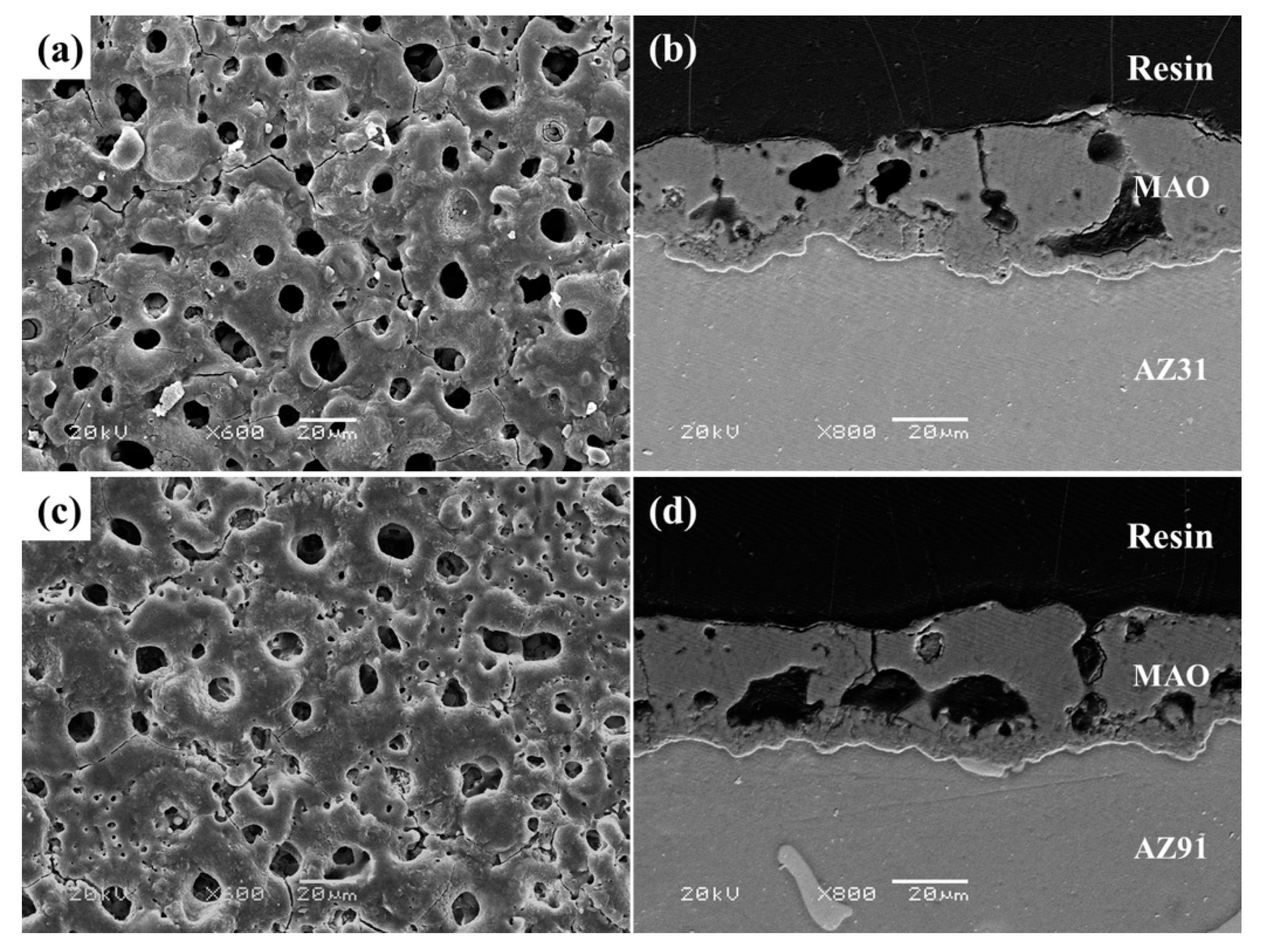
3.1. Microstructure and Composition

As shown in Figure 1, the microstructure of AZ31 alloy was composed of the equiaxed α-Mg grains and slight Al8Mn5 phases. AZ91 alloy was multi-phase containing mainly α-Mg matrix and β-phases (Mg17Al12). The phase compositions of AZ31 and AZ91 alloys have been verified in other research [25,26,27].
Figure 2 gives the morphologies of MAO coatings on AZ31 and AZ91 alloys. The two coatings had similar surface characteristics with numerous randomly distributed pores with a few micrometers in diameter. The micro-pores in MAO coatings are usually regarded as the trace of discharge [21]. Some micro-cracks existed on the coating surface, which were caused by the thermal stress generated during the MAO process [21,28]. In cross-section direction, the ceramic coatings could be divided into the porous outer layer and the dense inner layer.
Figure 3 reveals the XRD patterns of MAO treated AZ31 and AZ91 alloys, with the uncoated Mg alloys as a control. The observed diffraction peaks corresponded to α-Mg phase for AZ31 alloy, while the diffraction peaks corresponded to α-Mg and β-phases for AZ91 alloy, which matched well with the results in Figure 1. After MAO treatment, α-Mg phase was oxidized to MgO, and MgO was the major component of two ceramic coatings. The visible Mg peaks in two patterns suggested the penetration of the X-rays through the MAO coating into the substrate [29]. According to the SEM and XRD results, it could be concluded that MAO coatings grown on AZ31 and AZ91 alloys possessed similar microstructure and composition.

3.2. Corrosion Behaviors of AZ31 and AZ91 Mg Alloys

Figure 4 exhibits the Bode plots for the AZ31 and AZ91 alloys after immersion in 0.1 M NaCl solution for 0.5 h. A capacitive peak in high-medium frequency and an inductive peak in low frequency were observed in the Bode plots of the two alloys (Figure 4b). The capacitive peak reflected the charge transfer reaction of the Mg corrosion process, while the inductive peak was associated with the relaxation of adsorbed species, such as Mg(OH)2 [30]. Therefore, an equivalent circuit model in Figure 4a was used to fit a Bode plot. Rs was the solution resistance, Rct signified the charge transfer resistance in parallel with the double layer capacity CPE and RL represented the inductive resistance in series with an inductor L. The fitted values are listed in Table 1. The Rct and RL values of AZ91 alloy were much higher than that of AZ31 alloy, implying a better corrosion resistance of AZ91 alloy.
Immersion tests of Mg substrates were carried out in 0.1 M NaCl solution. The initial corrosion morphologies of Mg alloys are given in Figure 5. It can be seen that the corrosion form of AZ31 alloy was different from that of AZ91 alloy. Filament characteristics corresponding to the dark regions in Figure 5a were observed, indicating that the attack of AZ31 alloy was filiform corrosion. However, the corrosion form of the AZ91 alloy was micro-galvanic corrosion. As shown in Figure 5b, corrosion attack preferentially occurred on α-Mg matrix neighboring β-phase. Figure 6 shows photographs of the whole samples and SEMs of surface and cross-section morphologies of Mg alloys after 48 h immersion. The AZ31 alloy suffered from serious corrosion damage and corrosion products covered the entire sample surface (Figure 6a–c). The corrosion depth ranged from 50 to 95 μm. In contrast to the AZ31 alloy, corrosion appeared locally on the surface of the AZ91 alloy, did not spread across the entire surface, and extended deeply into the interior of alloy (Figure 6d–f). The maximum corrosion depth was more than 250 μm.
The XRD patterns of the uncoated AZ31 and AZ91 Mg alloys after 48 h immersion are given in Figure 7. In 0.1 M NaCl solution, Mg(OH)2 was observed to be the major corrosion product for the uncoated Mg alloys. In summary, AZ91 alloy had a better corrosion resistance than AZ31 alloy. The corrosion forms of AZ31 and AZ91 alloys were local corrosion, but specific corrosion mechanisms were different. The corrosion of AZ31 alloy was filiform corrosion, which was caused by an active corrosion cell moving across the metal surface [31]. Filiform corrosion was a threadlike superficial corrosion, however once initiated, the filaments developed rapidly and finally converted into a dense mesh of indiscernible filaments [32]. Corrosion could spread across the entire surface as immersion time proceeded. In AZ91 alloy, the β-phases tended to act as an active galvanic cathode, which accelerated the corrosion of α-Mg matrix when exposed to corrosive solution [33]. As a result, corrosion was concentrated in certain areas of the alloy surface and did not cover the entire surface, but penetrated deeply into the interior of alloy.

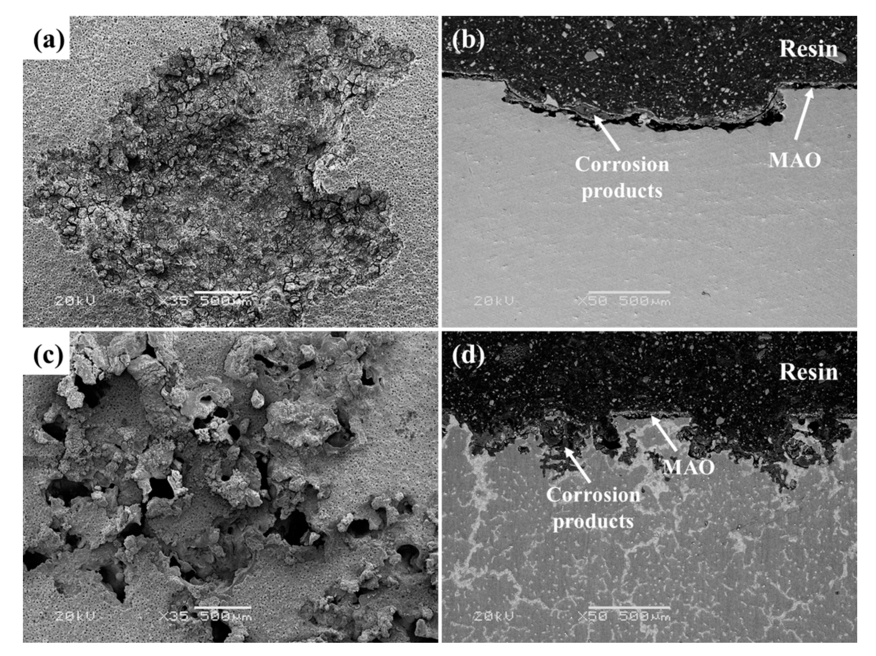
3.3. Corrosion Behaviors of MAO-Coated AZ31 and AZ91 Mg Alloys

Long-term EIS measurements were performed to study the deterioration process of MAO coatings. Figure 8 presents the Bode plots and fitting curves of MAO coatings on AZ31 and AZ91 alloys after different durations of exposure. In view of characteristics of MAO coatings and Bode diagrams, an equivalent circuit model with two time constants in Figure 8a was used. In the model, Rs represented the solution resistance. R1/CPE1 pair signified the resistance of outer porous layer of the MAO coating, and R2/CPE2 pair was the inner layer/interface resistance of the MAO coating [34]. The values of the fitting parameters are listed in Table 2 and Table 3.
After immersion in 0.1 M NaCl solution for 0.5 h, the resistance values (R1 and R2) of MAO-treated Mg alloys were much larger than the resistance values (Rct and RL) of Mg substrates, which implied that the corrosion resistance of Mg alloys was greatly enhanced by MAO treatment in the short term. Moreover, both MAO coatings degraded continually with immersion time, but the coating on AZ31 alloy appeared to degrade slightly faster. Further information can be obtained from Table 2 and Table 3. At the initial 0.5 h immersion, the R1 and R2 values of MAO coating on the AZ31 alloy were close to that on the AZ91 alloy. This proved that both coatings provided nearly the same corrosion protection to Mg substrates at the early stage of the immersion test, which was mainly related to the similar thickness and microstructure of the two coatings. After 2 h of exposure, the R1 values of the two coatings increased because the hydrated product, Mg(OH)2, in the outer layer of MgO could partially block the defects in coatings [15]. Subsequently, both coatings were detected to deteriorate along with the gradual drop in R1 and R2 values. After 20 h immersion, the failure of MAO coating on AZ31 alloy occurred and thus lead to the corrosion damage of substrate, as evidenced by the visible inductive loop in the phase angle Bode plots in Figure 8b. In comparison, for the MAO coating on AZ91 alloy, the inductive loop was detected after 30 h immersion (Figure 8d). These results indicated that MAO coating the AZ91 alloy could offer longer corrosion protection to the substrate than when it was applied to the AZ31 alloy.
Immersion tests were conducted in order to analyze the long-term corrosion performance of the MAO coatings on Mg alloys. The surface photographs taken of the MAO-coated Mg alloys during immersion tests are shown Figure 9. The surface of two specimens was featured by local corrosion with different levels of corrosion damage. After 105 h immersion, visible corrosion traces appeared on the surface of MAO-treated AZ31 alloy. The area of surface corrosion regions gradually increased with immersion time. By contrast, an obvious corrosion pit was not detected on the surface of MAO-treated AZ91 alloy until 150 h immersion. However, once corrosion occurred, the surface corrosion region of MAO-treated AZ91 alloy enlarged at a faster rate as compared with the AZ31 specimen.
Detailed corrosion morphologies of the MAO-treated AZ31 and AZ91 alloys after 60 h immersion are given in Figure 10. From the macroscopic appearance of the MAO-treated Mg alloys in Figure 9, no apparent corrosion traces could be observed by naked eye after 60 h immersion. However, obvious raised areas appeared on the surface micrographs in Figure 10a,c. The raised areas differed in shape: continuous filaments in the AZ31 sample and discrete balls in the AZ91 sample. The cross-section micrographs (Figure 10b,d) indicated that the elevated areas were associated with the corrosion products forming at the coating interface. The corrosion products lifted MAO coatings and thus lead to the formation of elevated areas.
Figure 11 shows the corrosion morphologies of the MAO-treated AZ31 and AZ91 alloys after 420 h immersion. The surface of MAO-treated AZ31 alloy showed an open pit with the maximal depth of 300 μm (Figure 11a,b). For the MAO-treated AZ91 alloy, the corrosion region was distributed discretely at the surface, and the maximal corrosion depth exceeded 500 μm (Figure 11c,d). Meanwhile, all discrete corrosion areas grew along the boundaries of the β-phases. In addition, it is worth mentioning that the corrosion depths of AZ31 and AZ91 specimens were much larger than their coating thicknesses, implying that the MAO coatings on top of corrosion areas were totally destroyed.

4. Discussion

Based on the above results, MAO coating of AZ91 alloy could offer longer corrosion protection to substrate in comparison with that of AZ31 alloy (Figure 8 and Figure 9). However, once corrosion occurred, the coated AZ91 alloy displayed a larger expanding rate of corrosion damage area than that the coated AZ31 alloy during immersion tests (Figure 9). Moreover, the two coatings differed in their corrosion damage morphologies (Figure 10 and Figure 11). The corrosion properties of MAO coating depended on the characteristics of coating and Mg substrate. The two coatings were very similar in microstructure and phase composition. Hence, the different corrosion features of the two coatings were mainly due to differences in the Mg substrates. The role of Mg substrates in the corrosion behavior of MAO coatings is elucidated in Figure 12.
When exposed to a corrosive medium, the corrosive medium penetrated easily into the porous outer layer through open micro-pores and continued to the dense inner layer (Figure 12a,d). At the same time the main constituent of oxide coatings (MgO) hydrated gradually to form Mg(OH)2, but this process did not cause peeling off of coatings [25]. As the immersion time proceeded, the corrosive medium reached the coating interface and contacted the substrate. After that, the corrosion of Mg substrates would quickly occur because of their poor corrosion resistance, resulting in the accumulation of corrosion products at the interface (Figure 12b,e).
Both MgO and Mg(OH)2 possess a larger molar volume than Mg [15,25], so the volume of Mg substrates tended to expand after corrosion. The increasing volume of corrosion products produced an upward stress to MAO coatings, and thus lifted the coatings (Figure 10a,b). Excessive volume increase was able to cause peeling off of coatings (Figure 10d). Therefore, the corrosion form of the Mg substrate significantly contributed to the failure process of coatings, because it determined the accumulation mode of corrosion product at the interface, which was the source of the stress. The MAO-coated Mg alloy should be regarded as a system of coating and substrate.
When the corrosion medium reached the interface, the initial corrosion of AZ91 substrate happened after longer immersion as compared with AZ31 substrate because of the better corrosion resistance of AZ91 substrate. Consequently, the corrosion damage to AZ91 substrate was detected after longer exposure (Figure 4). The corrosion forms of AZ31 and AZ91 substrates were filiform and micro-galvanic corrosion (Figure 5), respectively. Filiform corrosion was a kind of superficial corrosion, which developed rapidly to surrounding areas but slowly to the interior of substrate. Less corrosion products accumulated in certain regions of the interface and exerted less stress to the coating on AZ31 substrate, which could only lift the coating (Figure 12b). The oxide coating could still provide a certain degree of corrosion protection to the substrate. As for AZ91 substrate, although AZ91 substrate had better corrosion resistance, micro-galvanic corrosion penetrated deeply into the interior of substrate as exposed to corrosive medium. Within the same immersion time, excessive corrosion products formed at certain regions of the interface, leading to the peeling off of the coating (Figure 12e). This in turn facilitated the penetration of corrosion medium into AZ91 substrate. Consequently, the area of corrosion damage for MAO coating on AZ91 alloy enlarged at a faster rate than that on AZ31 alloy.

5. Conclusions

1. The MAO coatings on AZ31 and AZ91 Mg alloys possessed similar porous structure and phase composition. However, in EIS tests, the failure of MAO coating on AZ31 and AZ91 alloys occurred after 20 h and 30 h, respectively. During immersion testing in 0.1 M NaCl solution, visible corrosion traces appeared after 105 h immersion for the MAO-treated AZ31 alloy and 150 h for AZ91 specimens. The MAO coating on AZ91 alloy provided a longer-term corrosion protection to substrate than when applied to AZ31 alloy, due to the better corrosion resistance of AZ91 alloy. Moreover, once corrosion occurred, the MAO coating on AZ91 alloy displayed a larger expanding rate of corrosion area than when applied to AZ31 alloy during immersion tests, and their corrosion damage morphologies were different. This was largely attributed to the different corrosion forms of Mg substrates.
2. Failures of MAO coatings resulted mainly from the volume increase of corrosion products at the interface which put upward stress on coatings. The corrosion form of Mg substrate contributed significantly to the failure process of MAO coatings, because it determined the accumulation mode of corrosion products at the interface. The corrosion forms of AZ31 and AZ91 substrates were filiform and micro-galvanic corrosion, respectively. The different corrosion features of Mg substrates resulted in the different corrosion morphologies and expanding rates of surface corrosion area for the two coatings.

Author Contributions

Conceived and designed the experiments, C.L., H.L. and B.J.; performed the experiments and collected the data, C.L. and J.Y.; analyzed the data and drafted the paper, C.L. and J.Y.; revised the paper, H.L.; offered the funding, C.L. and B.J.

Funding

This research was funded by China Postdoctoral Science Foundation (No. 51203237) and the National Natural Science Foundation of China (No. 51901099, 51571114).

Conflicts of Interest

The authors declare no conflict of interest.

References

  1. Mordike, B.L.; Ebert, T. Magnesium properties-applications-potential. Mater. Sci. Eng. A 2001, 302, 37–45. [Google Scholar] [CrossRef]
  2. Kulekci, M.K. Magnesium and its alloys applications in automotive industry. J. Adv. Manuf. Technol. 2008, 39, 851–865. [Google Scholar] [CrossRef]
  3. Song, G.L.; Atrens, A. Understanding magnesium corrosion-a frame work for improved alloy performance. Adv. Eng. Mater. 2003, 5, 837–858. [Google Scholar] [CrossRef]
  4. Gray, J.E.; Luan, B. Protective coatings on magnesium and its alloys-a critical review. J. Alloy. Compd. 2002, 336, 88–113. [Google Scholar] [CrossRef]
  5. Zhang, D.F.; Qi, Z.B.; Wei, B.B.; Shen, H.; Wang, Z.C. Microstructure and corrosion behaviors of conductive Hf/HfN multilayer coatings on magnesium alloys. Ceram. Int. 2018, 44, 9958–9966. [Google Scholar] [CrossRef]
  6. Chen, D.; Wang, R.Q.; Huang, Z.Q.; Wu, Y.K.; Zhang, Y.; Wu, G.R.; Li, D.L.; Guo, C.H.; Jiang, G.R.; Yu, S.X.; et al. Evolution processes of the corrosion behavior and structural characteristics of plasma electrolytic oxidation coatings on AZ31 magnesium alloy. Appl. Surf. Sci. 2018, 434, 326–335. [Google Scholar] [CrossRef]
  7. Dey, A.; Rani, R.U.; Thota, H.K.; Sharma, A.K.; Bandyopadhyay, P.; Mukhopadhyay, A.K. Microstructural, corrosion and nanomechanical behaviour of ceramic coatings developed on magnesium AZ31 alloy by micro arc oxidation. Ceram. Int. 2013, 39, 3313–3320. [Google Scholar] [CrossRef]
  8. Hussein, R.O.; Nie, X.; Northwood, D.O. An investigation of ceramic coating growth mechanisms in plasma electrolytic oxidation (PEO) processing. Electrochim. Acta 2013, 112, 111–119. [Google Scholar] [CrossRef]
  9. Curran, J.A.; Clyne, T.W. Porosity in plasma electrolytic oxide coatings. Acta Mater. 2006, 54, 1985–1993. [Google Scholar] [CrossRef]
  10. Pezzato, L.; Brunelli, K.; Napolitani, E.; Magrini, M.; Dabalà, M. Surface properties of AZ91 magnesium alloy after PEO treatment using molybdate salts and low current densities. Appl. Surf. Sci. 2015, 357, 1031–1039. [Google Scholar] [CrossRef]
  11. Mori, Y.; Koshi, A.; Liao, J.S.; Asoh, H.; Ono, S. Characteristics and corrosion resistance of plasma electrolytic oxidation coatings on AZ31B Mg alloy formed in phosphate-silicate mixture electrolytes. Corros. Sci. 2014, 88, 254–262. [Google Scholar] [CrossRef]
  12. Rendon, M.E.; Duque, V.; Quintero, D.; Harmsen, M.C.; Echeverria, F. Novel coatings obtained by plasma electrolytic oxidation to improve the corrosion resistance of magnesium-based biodegradable implants. Surf. Coat. Technol. 2018, 354, 28–37. [Google Scholar] [CrossRef]
  13. Zhuang, J.J.; Guo, Y.Q.; Xiang, N.; Xiong, Y.; Hu, Q.; Song, R.G. A study on microstructure and corrosion resistance of ZrO2-containing PEO coatings formed on AZ31 Mg alloy in phosphate-based electrolyte. Appl. Surf. Sci. 2015, 357, 1463–1471. [Google Scholar] [CrossRef]
  14. Lin, X.; Tan, L.L.; Zhang, Q.; Yang, K.; Hu, Z.Q.; Qiu, J.H.; Cai, Y. The in vitro degradation process and biocompatibility of a ZK60 magnesium alloy with a forsterite-containing micro-arc oxidation coating. Acta Biomater. 2013, 9, 8631–8642. [Google Scholar] [CrossRef] [PubMed]
  15. Liang, J.; Bala Srinivasan, P.; Blawert, C.; Dietzel, W. Influence of chloride ion concentration on the electrochemical corrosion behaviour of plasma electrolytic oxidation coated AM50 magnesium alloy. Electrochim. Acta 2010, 55, 6802–6811. [Google Scholar] [CrossRef] [Green Version]
  16. Wang, L.Q.; Zhou, J.S.; Liang, J.; Chen, J.M. Corrosion mechanism of plasma electrolytic oxidation coated magnesium alloy with laser surface melting pretreatment. J. Electrochem. Soc. 2014, 161, C20–C24. [Google Scholar] [CrossRef]
  17. Lin, X.; Wang, X.; Tan, L.L.; Wan, P.; Yu, X.M.; Li, Q.; Yang, K. Effect of preparation parameters on the properties of hydroxyapatite containing micro-arc oxidation coating on biodegradable ZK60 magnesium alloy. Ceram. Int. 2014, 40, 10043–10051. [Google Scholar] [CrossRef]
  18. Sankara Narayanan, T.S.N.; Park, I.S.; Lee, M.H. Strategies to improve the corrosion resistance of microarc oxidation (MAO) coated magnesium alloys for degradable implants: Prospects and challenges. Prog. Mater. Sci. 2014, 60, 1–71. [Google Scholar] [CrossRef]
  19. Ono, S.; Moronuki, S.; Mori, Y.; Koshi, A.; Liao, J.S.; Asoh, H. Effect of electrolyte concentration on the structure and corrosion resistance of anodic films formed on Magnesium through plasma electrolytic oxidation. Electrochim. Acta 2017, 240, 415–423. [Google Scholar] [CrossRef]
  20. Tjiang, F.; Ye, L.W.; Huang, Y.J.; Chou, C.C.; Tsai, D.S. Effect of processing parameters on soft regime behavior of plasma electrolytic oxidation of magnesium. Ceram. Int. 2017, 43, S567–S572. [Google Scholar] [CrossRef]
  21. Wei, F.F.; Zhang, W.; Zhang, T.; Wang, F.H. Effect of variations of Al content on microstructure and corrosion resistance of PEO coatings on Mg-Al alloys. J. Alloys Compd. 2017, 690, 195–205. [Google Scholar] [CrossRef]
  22. Tekin, K.C.; Malayoğlu, U.; Shrestha, S. Electrochemical behavior of plasma electrolytic oxide coatings on rare earth element containing Mg alloys. Surf. Coat. Technol. 2013, 236, 540–549. [Google Scholar] [CrossRef]
  23. Chen, Y.; Yang, Y.; Zhang, W.; Zhang, T.; Wang, F.H. Influence of second phase on corrosion performance and formation mechanism of PEO coating on AZ91 Mg alloy. J. Alloys Compd. 2017, 718, 92–103. [Google Scholar] [CrossRef]
  24. Muhaffel, F.; Mert, F.; Cimenoglu, H.; Höche, D.; Zheludkevich, M.L.; Blawer, C. Characterisation and corrosion behaviour of plasma electrolytic oxidation coatings on high pressure die cast Mg-5Al-0.4Mn-xCe (x=0, 0.5, 1) alloys. Surf. Coat. Technol. 2015, 269, 200–211. [Google Scholar] [CrossRef]
  25. Liu, C.C.; Liang, J.; Zhou, J.S.; Li, Q.B.; Wang, L.Q. Characterization of AZ31 magnesium alloy by duplex process combining laser surface melting and plasma electrolytic oxidation. Appl. Surf. Sci. 2016, 382, 47–55. [Google Scholar] [CrossRef]
  26. Jia, R.L.; Zhang, M.; Zhang, L.; Zhang, W.; Guo, F. Correlative change of corrosion behavior with the microstructure of AZ91 Mg alloy modified with Y additions. J. Alloys Compd. 2015, 634, 263–271. [Google Scholar] [CrossRef]
  27. Liu, C.C.; Zheng, H.; Gu, X.; Jiang, B.L.; Liang, J. Effect of severe shot peening on corrosion behavior of AZ31 and AZ91 magnesium alloys. J. Alloys Compd. 2019, 770, 500–506. [Google Scholar] [CrossRef]
  28. Joni, M.S.; Fattah-alhosseini, A. Effect of KOH concentration on the electrochemical behavior of coatings formed by pulsed DC micro-arc oxidation (MAO) on AZ31B Mg alloy. J. Alloys Compd. 2016, 661, 237–244. [Google Scholar] [CrossRef]
  29. Cui, X.J.; Liu, C.H.; Yang, R.S.; Li, M.T.; Lin, X.Z. Self-sealing micro-arc oxidation coating on AZ91D Mg alloy and its formation mechanism. Surf. Coat. Technol. 2015, 269, 228–237. [Google Scholar] [CrossRef]
  30. Arrabal, R.; Pardo, A.; Merino, M.C.; Mohedano, M.; Casajús, P.; Matykina, E.; Skeldon, P.; Thompson, G.E. Corrosion behaviour of a magnesium matrix composite with a silicate plasma electrolytic oxidation coating. Corros. Sci. 2010, 52, 3738–3749. [Google Scholar] [CrossRef]
  31. Zhang, J.; Wu, C.Y. Corrosion protection behavior of AZ31 magnesium alloy with cathodic electrophoretic coating pretreated by silane. Prog. Org. Coat. 2009, 66, 387–392. [Google Scholar] [CrossRef]
  32. Samaniego, A.; Llorente, I.; Feliu, S., Jr. Combined effect of composition and surface condition on corrosion behavior of magnesium alloys AZ31 and AZ61. Corros. Sci. 2013, 68, 66–71. [Google Scholar] [CrossRef]
  33. Song, G.L.; Atrens, A.; Dargusch, M. Influence of microstructure on the corrosion of diecast AZ91D. Corros. Sci. 1999, 41, 249–273. [Google Scholar] [CrossRef]
  34. Liang, J.; Bala Srinivasan, P.; Blawert, C.; Störmer, M.; Dietzel, W. Electrochemical corrosion behaviour of plasma electrolytic oxidation coatings on AM50 magnesium alloy formed in silicate and phosphate based electrolytes. Electrochim. Acta 2009, 54, 3842–3850. [Google Scholar] [CrossRef]
Figure 1. Optical micrographs of the bare AZ31 (a) and AZ91 (b) Mg alloys.
Metals 09 01100 g001
Figure 2. Surface and cross-section SEM micrographs of MAO coatings on (a,b) AZ31 and (c,d) AZ91 Mg alloys.
Metals 09 01100 g002
Figure 3. (a) XRD patterns of the uncoated AZ31 and AZ91 Mg alloys; (b) XRD patterns of the MAO treated AZ31 and AZ91 Mg alloys.
Metals 09 01100 g003
Figure 4. Bode plots (a,b) for the bare AZ31 and AZ91 Mg alloys after immersion in 0.1 M NaCl solution for 0.5 h. The illustration in (a) is the equivalent circuit model for fitting the Bode plots.
Metals 09 01100 g004
Figure 5. Surface corrosion morphologies of the uncoated AZ31 (a) and AZ91 (b) Mg alloys after 20 min immersion in 0.1 M NaCl solution.
Metals 09 01100 g005
Figure 6. Photographs, surface and cross-section morphologies of the uncoated AZ31 (ac) and AZ91 (df) alloys after 48 h immersion in 0.1 M NaCl solution. (b,c,e,f) are SEM images.
Metals 09 01100 g006
Figure 7. XRD patterns of the uncoated AZ31 and AZ91 Mg alloys after 48 h immersion in 0.1 M NaCl solution.
Metals 09 01100 g007
Figure 8. Bode plots and fitting curves of MAO coatings on AZ31 (a,b) and AZ91 (c,d) alloys after immersion in 0.1 M NaCl solution for different times. The illustration is the equivalent circuit model for fitting the Bode plots before local corrosion failure.
Metals 09 01100 g008
Figure 9. Photographs of the MAO-treated AZ31 (a) and AZ91 (b) alloys after immersion in 0.1 M NaCl solution for different times.
Metals 09 01100 g009
Figure 10. Surface and cross-section micrographs of the MAO-treated AZ31 (a,b) and AZ91 (c,d) alloys after 60 h immersion in 0.1 M NaCl solution.
Metals 09 01100 g010
Figure 11. Surface and cross-section micrographs of the MAO-treated AZ31 (a,b) and AZ91 (c,d) alloys after 420 h immersion in 0.1 M NaCl solution.
Metals 09 01100 g011
Figure 12. Schematic diagrams for the failure processes of MAO coatings on AZ31 (ac) and AZ91 (df) alloys.
Metals 09 01100 g012
Table 1. EIS fitting results for the bare AZ31 and AZ91 Mg alloys after immersion in 0.1 M NaCl solution for 0.5 h.
SampleCPE-TCPE-PRct (Ω·cm2)L (H)RL (Ω·cm2)
AZ315.32 × 10−60.931.92 × 1031.06 × 1031.24 × 103
AZ914.74 × 10−60.916.98 × 1031.84 × 1043.72 × 104
Table 2. EIS-fitting results for MAO coating on AZ31 alloy after immersion in 0.1 M NaCl solution for different times.
Time (h)(CPE-T)1(CPE-P)1R1 (Ω·cm2)(CPE-T)2(CPE-P)2R2 (Ω·cm2)
0.54.13 × 10−70.759.86 × 1049.82 × 10−70.768.62 × 106
21.02 × 10−60.702.64 × 1054.86 × 10−70.894.08 × 106
51.34 × 10−60.799.57 × 1028.32 × 10−70.863.75 × 106
101.14 × 10−60.832.84 × 1021.88 × 10−60.831.96 × 106
Table 3. EIS fitting results for MAO coating on AZ91 alloy after immersion in 0.1 M NaCl solution for different times.
Time (h)(CPE-T)1(CPE-P)1R1 (Ω·cm2)(CPE-T)2(CPE-P)2R2 (Ω·cm2)
0.55.38 × 10−70.739.58 × 1046.16 × 10−70.667.96 × 106
28.47 × 10−70.711.01 × 1053.75 × 10−70.824.30 × 106
56.98 × 10−70.743.55 × 1046.30 × 10−70.723.86 × 106
101.21 × 10−60.701.41 × 1031.36 × 10−70.862.16 × 106
207.31 × 10−60.737.34 × 1025.01 × 10−70.791.02 × 106

