Initial Transfer Behavior and Solidification Structure Evolution in a Large Continuously Cast Bloom with a Combination of Nozzle Injection Mode and M-EMS

 ,
, 
Abstract
:1. Introduction
2. Model Descriptions
2.1. Basic Assumptions of the Model
- During the electromagnetic stirring process, the magnetic Reynolds number of the molten steel is small, ignoring the influence of the molten steel flow on the magnetic field.
- Under low-frequency agitation, the electromagnetic field can be regarded as a magnetic quasi-static field, ignoring the displacement current, and using the time-average electromagnetic force instead of the transient value.
- Ignoring the anisotropy of the material, it is considered that the molten steel, copper tube, and iron core are all isotropic materials, and physical properties such as conductivity and magnetic permeability are treated as constants.
- The low-Reynolds number model is adopted to simulate the turbulence in the mold, and the mushy zone is treated as a porous medium, where the flow obeys Darcy’s law.
- The molten steel is assumed to be an incompressible Newtonian fluid. The viscosity, specific heat, and thermal conductivity are assumed to be constants.
- The influence of mold oscillation and mold curvature on the fluid flow is not considered.
2.2. Governing Equations
2.2.1. Electromagnetic Field
2.2.2. Flow and Solidification
- The continuity equation is as follows:where is the density of steel and is the velocity component in the direction of the stream.
- The momentum equation is as follows:where is the pressure and is the effect viscosity coefficient, which can be defined as follows:where is the laminar viscosity and is the turbulent viscosity, which can be defined as follows:where and are constants in the low Reynolds number turbulence two-equation model, is the turbulent energy, and is the turbulent energy dissipation rate, which can be calculated by the low Reynolds number turbulence two-equation model [13]. is the electromagnetic force and is the thermal buoyancy, defined as follows:where is the thermal expansion coefficient, is the temperature, and is the liquidus temperature. accounts for the phase interaction force within the mushy zone, which can be described by Darcy’s law:where is a mushy zone constant that has a great influence on the calculation of flow and solidification; in this study, it is set to 5 × 10⁸ to obtain the most accurate results. is the casting speed; is the liquid fraction and is given by the lever rule in the mushy zone as follows:where is the solidus temperature and is the solid fraction.
- The energy equation is as follows:where is the total enthalpy, defined as follows:where is the sensible enthalpy, is the specific heat, is the latent heat of molten steel solidification, and is the effective thermal conductivity, which can be defined as follows:where is the thermal conductivity and is the turbulent Prandtl number, which is set to 0.9 [14].
2.3. Boundary Conditions
2.3.1. Electromagnetic Field
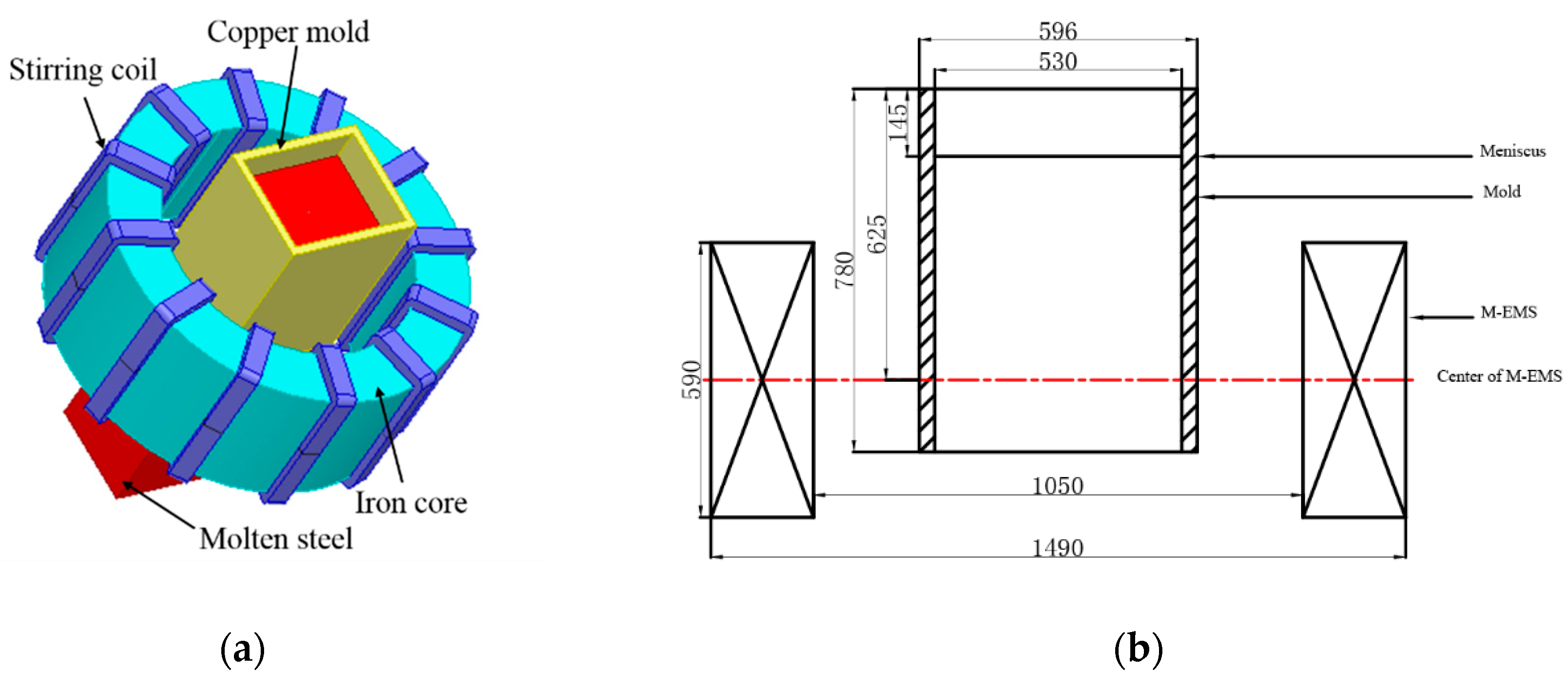
- Three pairs of coil windings are loaded with a three-phase alternating current; the phase difference of each phase is 120°.
- The magnetic flux lines are parallel to the boundary at the external surfaces of the surrounding air unit.
- Insulation boundary conditions are imposed between the electromagnetic stirrer coil and the iron core.
2.3.2. Flow and Solidification
- Inlet of nozzle: the inlet velocity is derived from the mass conservation relationship of the bloom casting. The inlet temperature is the casting temperature, and the turbulent kinetic energy and turbulent dissipation rate at the inlet are calculated according to the empirical formulas [15]:where is the velocity of the nozzle inlet and is the diameter of the nozzle.
- Outlet of computation domain: the fully developed flow condition is adopted, where the normal gradients of all variables are set to 0.
- Free surface: Considering the insulation effect of the mold flux, the free surface is set to be adiabatic and the shear stress is 0.
- Wall surface: a non-slip wall surface is adopted and the nozzle wall is set to adiabatic. The heat flux boundary condition is applied on the mold zone according to Li [10]:where is the heat flux density. The convective heat transfer boundary condition is imposed on the secondary cooling zone. The integrated heat transfer coefficient is calculated by [10]:(Water spray region)(Air-mist spray region)where and are the cooling water volume flow rate with a unit of L·m−2·s−1 and L·m−2·min−1, respectively.
2.4. Numerical Solution Procedure
3. Results and Discussion of Calculation
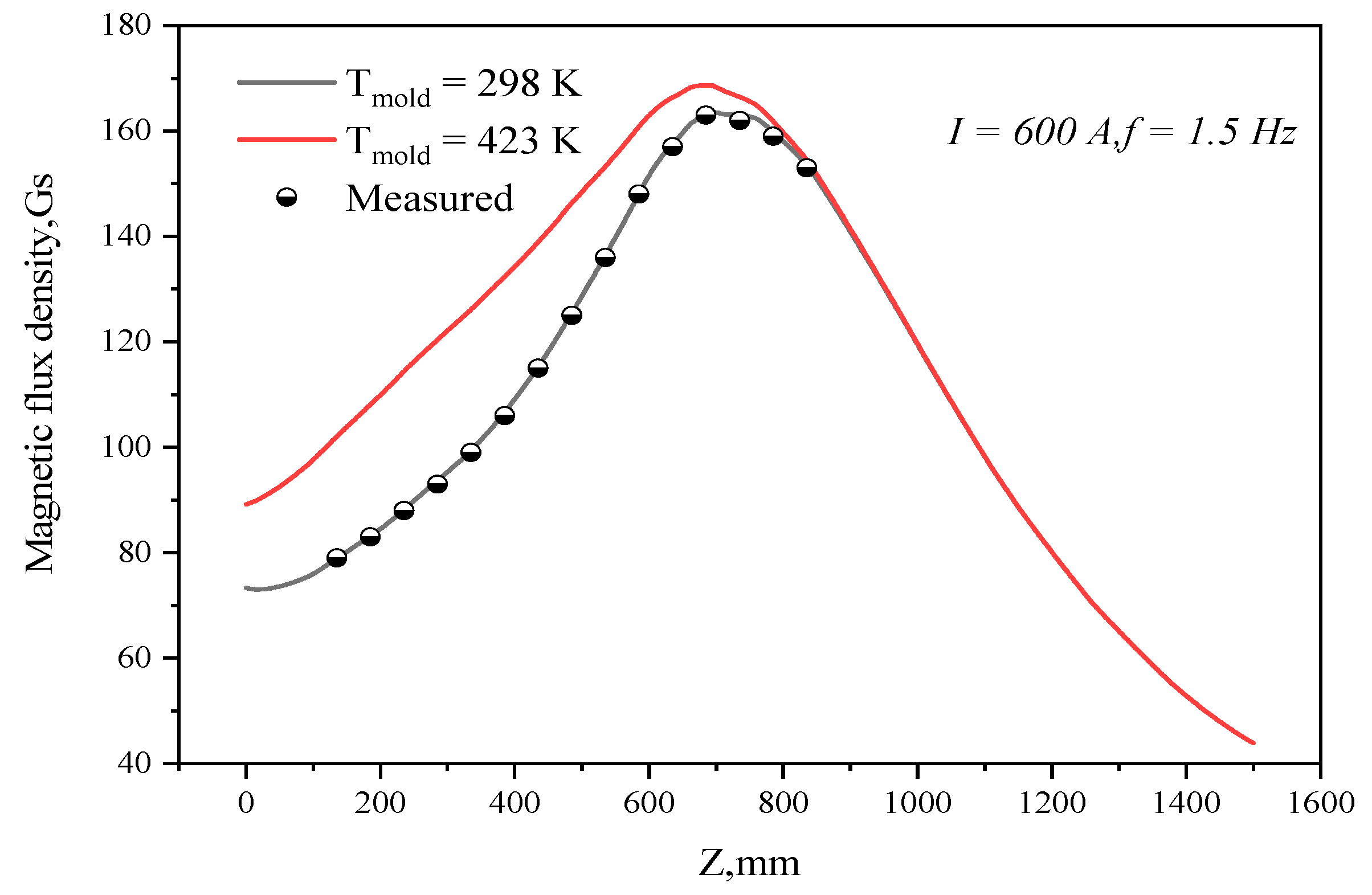
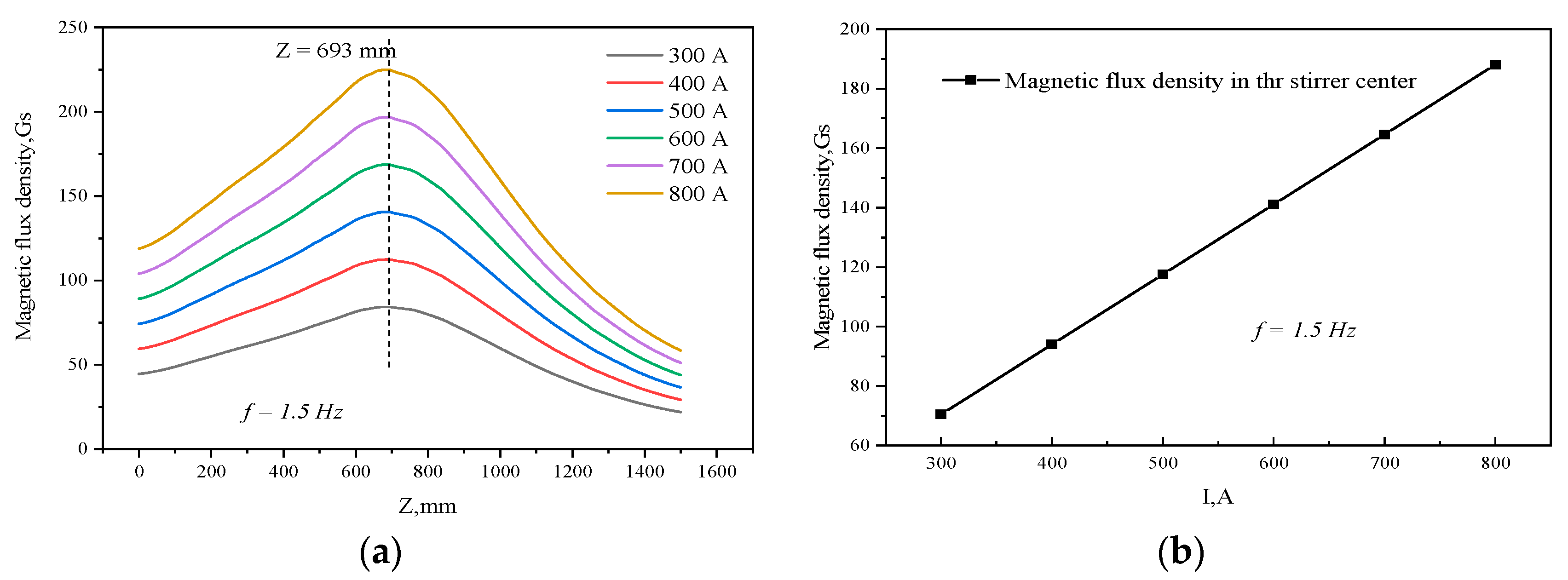
3.1. Electromagnetic Field Simulation Analysis
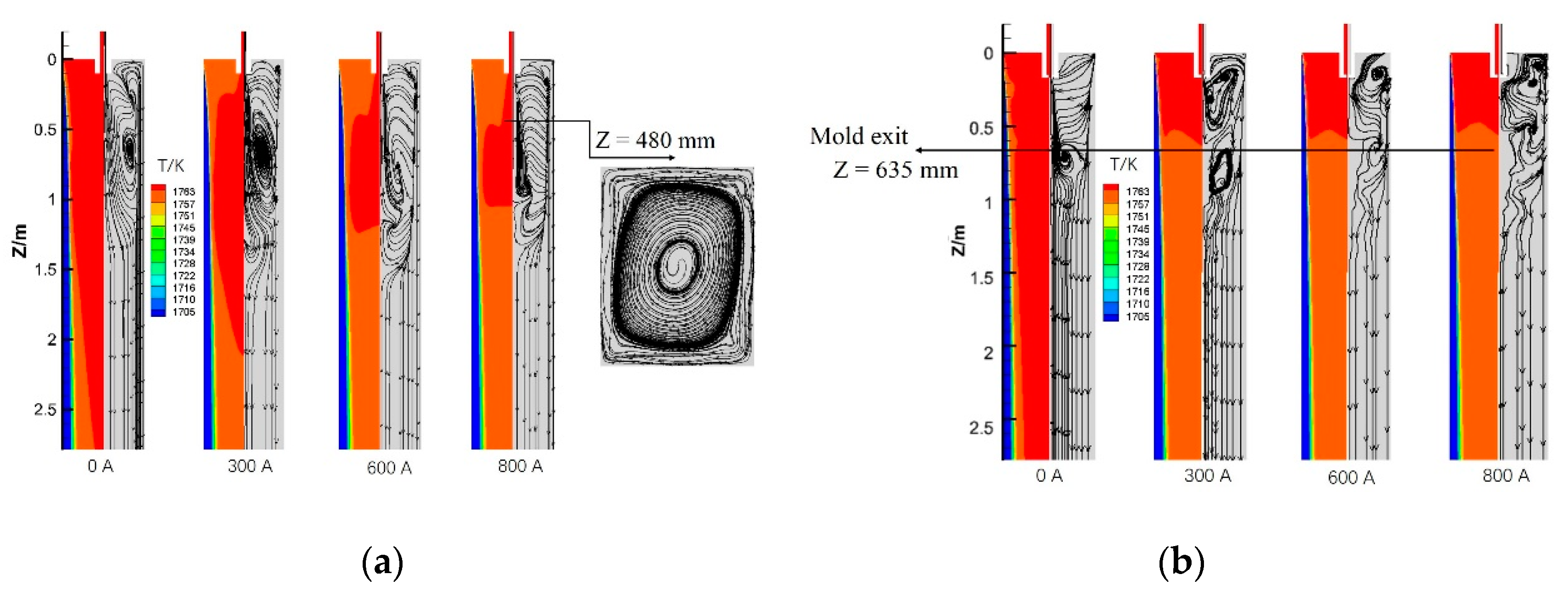
3.2. Simulation Analysis of Flow, Heater Transfer, and Solidification
4. Results and Discussion
5. Conclusions
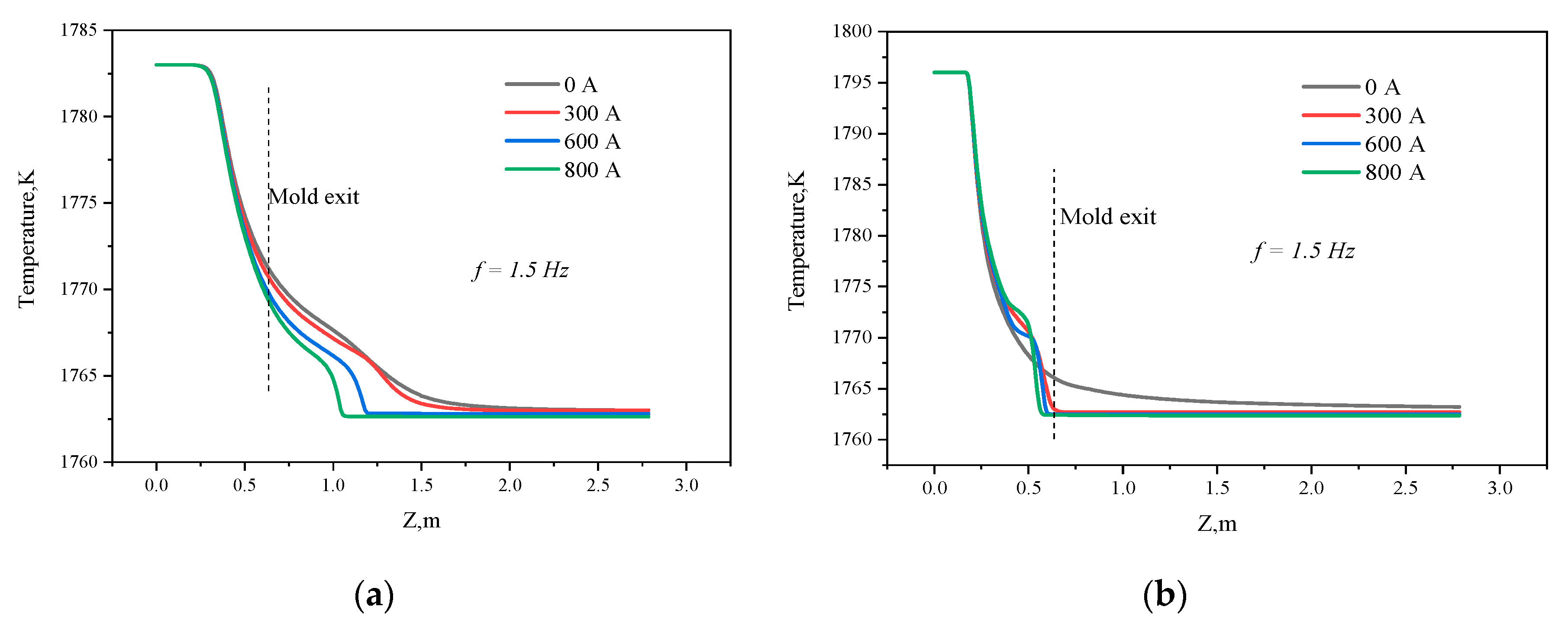
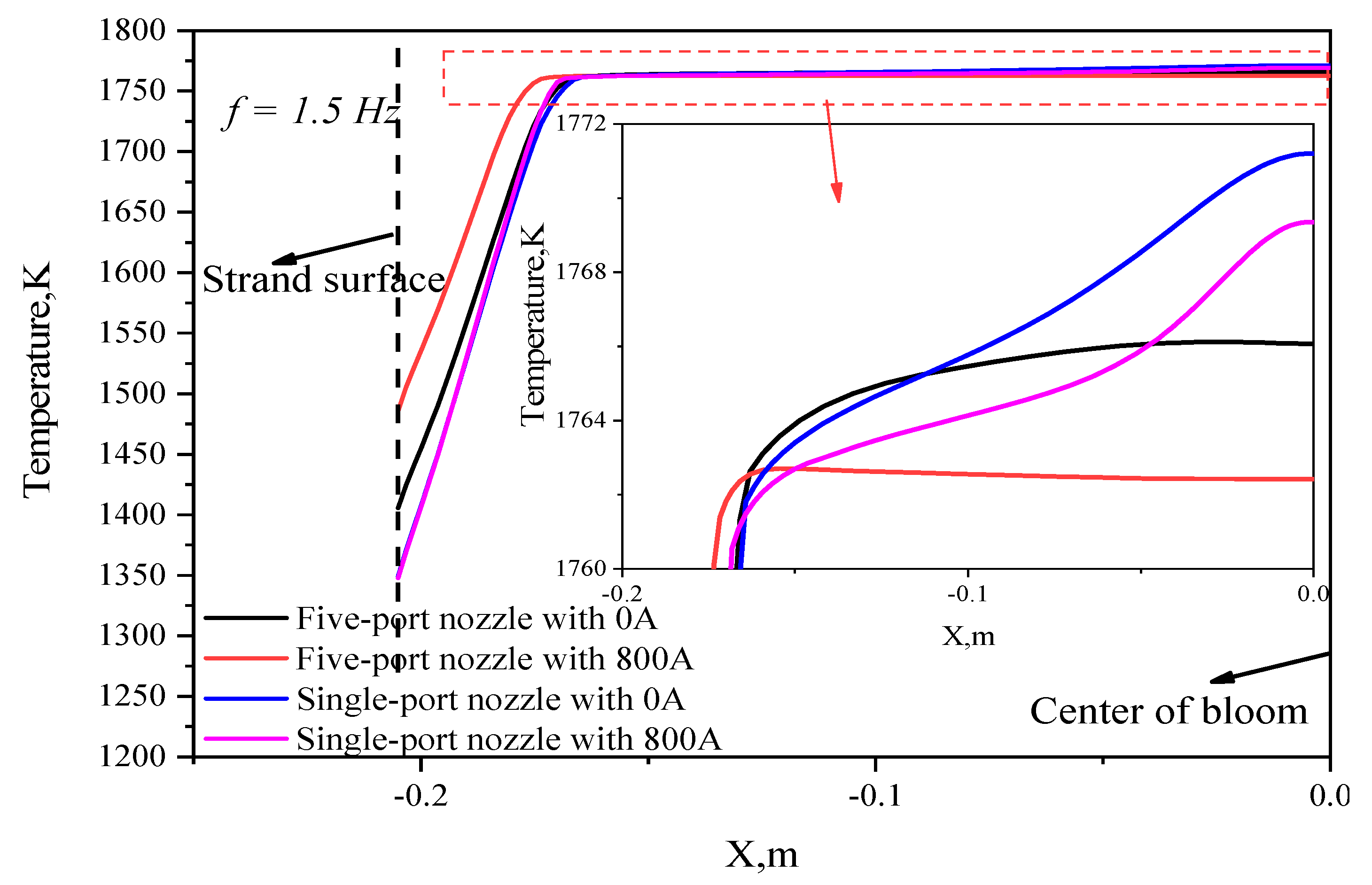
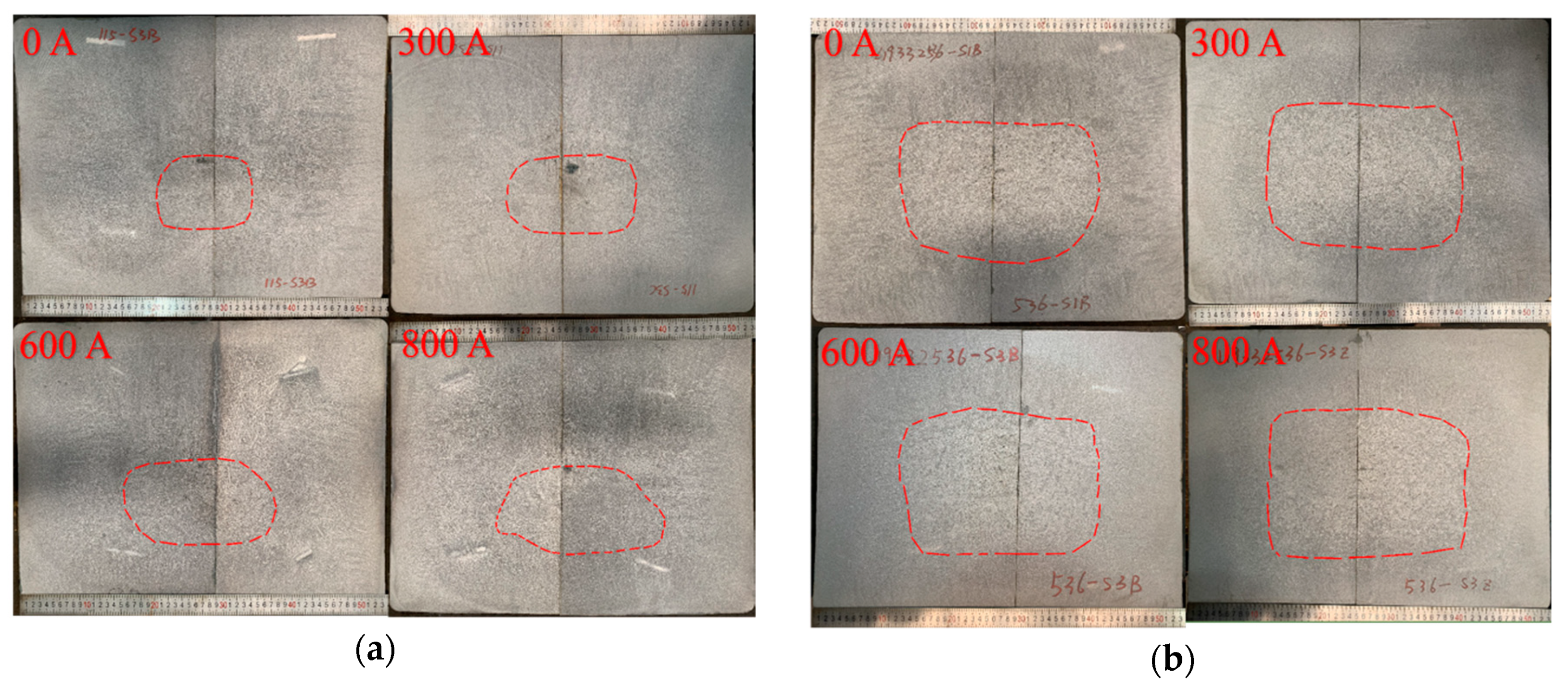
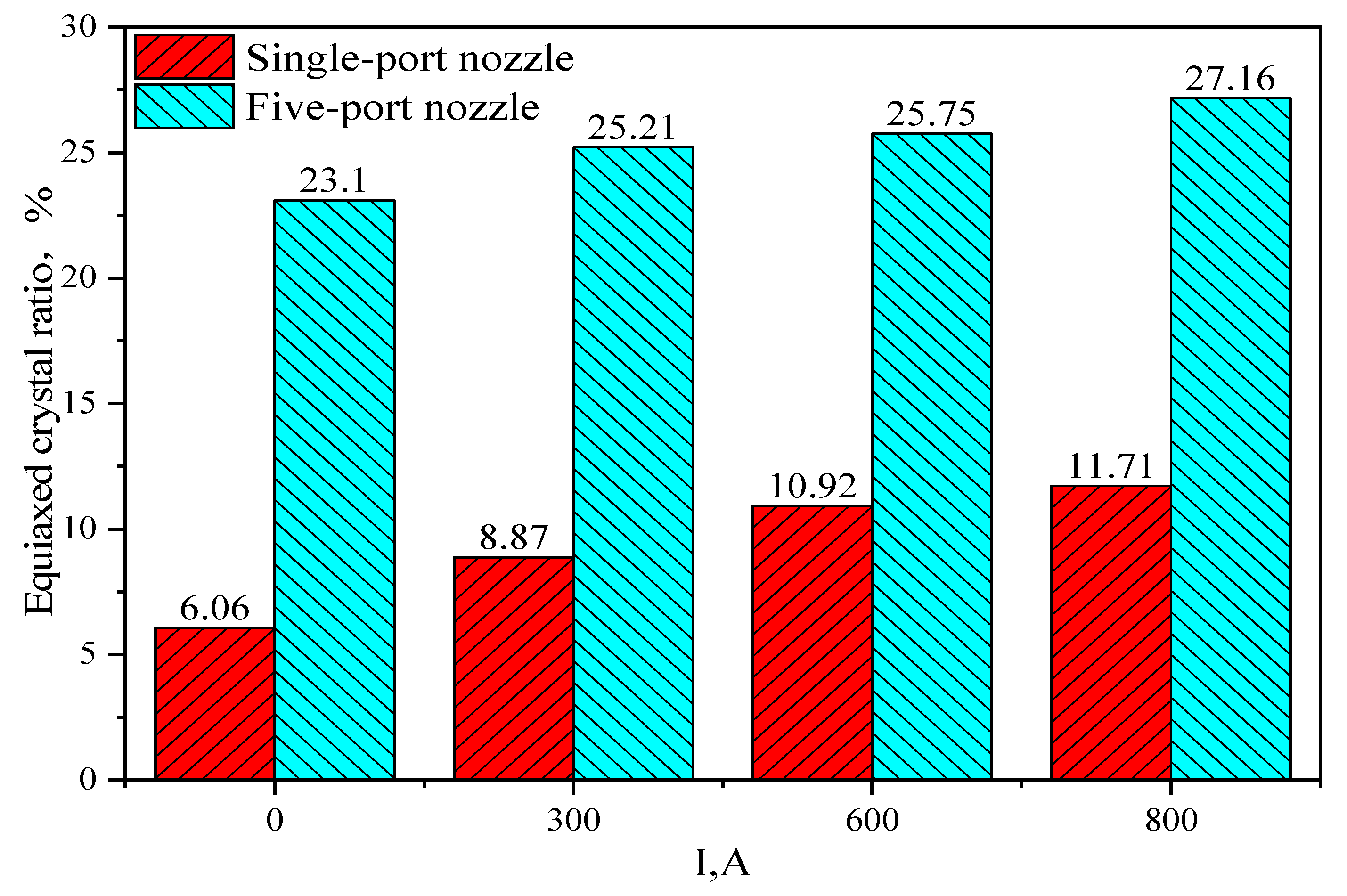
- M-EMS can introduce a horizontal swirling flow ahead of the solidification front, promoting the superheat dissipation of molten steel and columnar to equiaxed transition (CET). When the current increases from 0 A to 800 A, the equiaxed crystal ratio in the single-port nozzle and five-port nozzle injection modes increases from 6.06% and 23.1% to 11.71% and 27.15%, respectively.
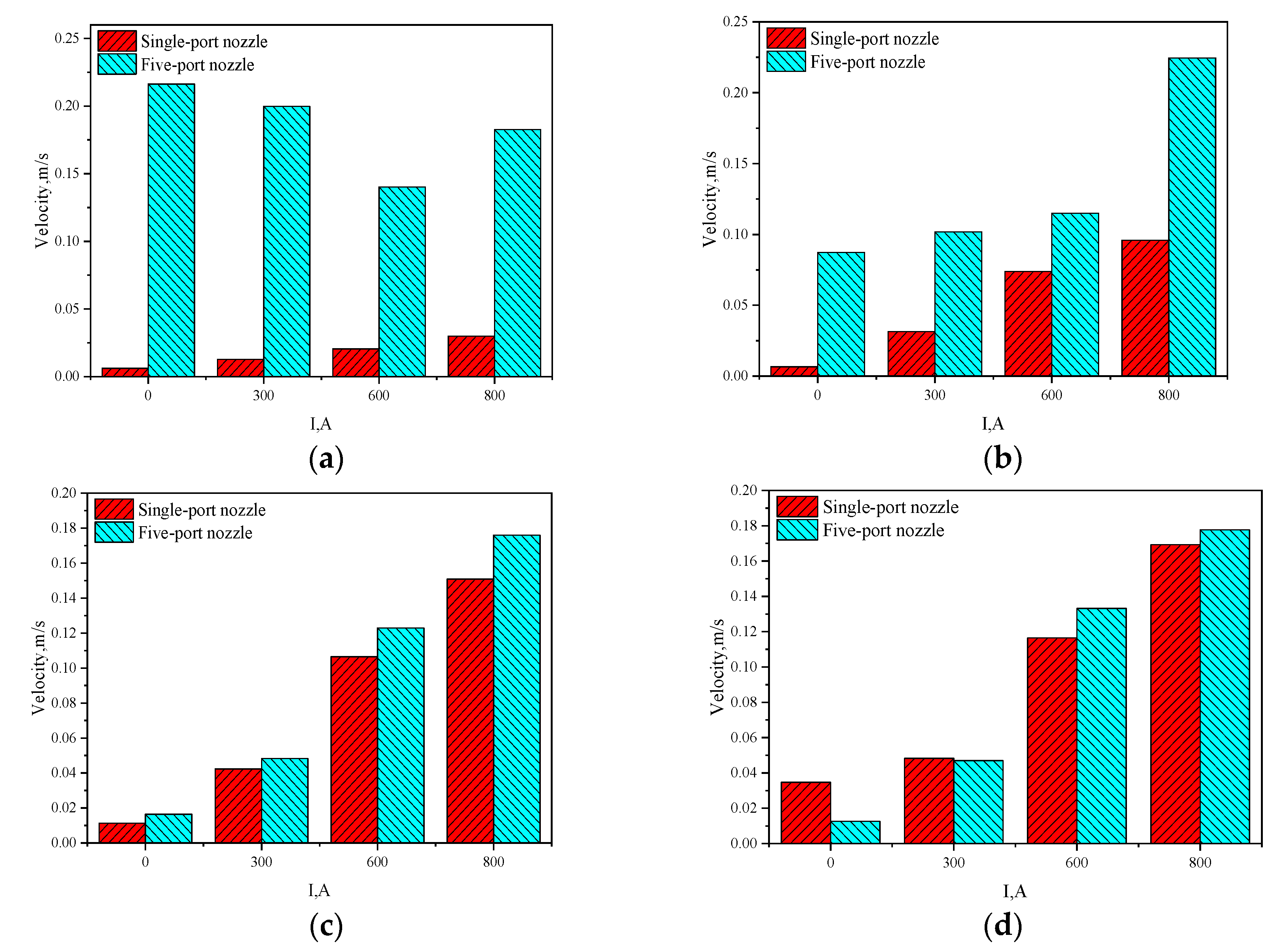
- It is found that the flow velocity of the molten steel in front of the solidification interface for the five-port nozzle is higher than that for the single-port nozzle regardless of the M-EMS power. The washing effect here reinforces both the heat exchange through the solidification interface and the dendrite re-melting or fragmenting, stimulating the formation of equiaxed crystal in the bloom center.
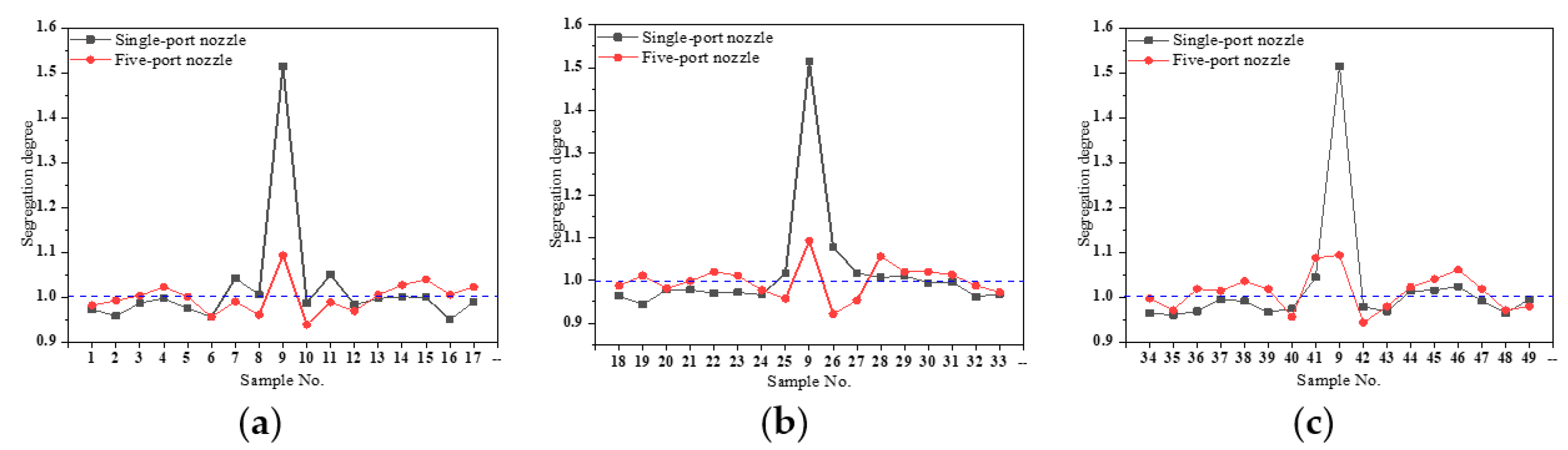
- The carbon content range is reduced from 0.279% in the single-port nozzle to 0.080% for the five-port nozzle injection mode. The central shrinkage is obviously improved for the five-port nozzle injection mode, which means the combination of a five-port nozzle and M-EMS is an important and effective way to control the as-cast macrostructure and internal quality of carbon 45 steel blooms.
Author Contributions
Funding
Acknowledgments
Conflicts of Interest
References
- He, M.; Wang, N. Physical and Numerical Simulation of the Fluid Flow and Temperature Distribution in Bloom Continuous Casting Mold. Steel Res. Int. 2017, 88, 1600447. [Google Scholar] [CrossRef]
- Spitzer, K.H.; Dubke, M. Rotational electromagnetic stirring in continuous casting of round strands. Metall. Mater. Trans. B 1986, 17, 119. [Google Scholar] [CrossRef]
- Geng, X.; Li, X. Optimisation of electromagnetic field and flow field in round billet continuous casting mould with electromagnetic stirring. Ironmak. Steelmak. 2015, 42, 675–682. [Google Scholar] [CrossRef]
- Ayata, K.; Mori, H. Low superheat teeming with electromagnetic stirring. ISIJ Int. 1995, 35, 680–685. [Google Scholar] [CrossRef]
- Yokoya, S.; Takagi, S. Swirling flow effect in off-center immersion nozzle on bulk flow in billet continuous casting mold. ISIJ Int. 2001, 41, 1215–1220. [Google Scholar] [CrossRef]
- Sun, H.; Zhang, J. Effect of feeding modes of molten steel on the mould metallurgical behavior for round bloom casting. ISIJ Int. 2011, 51, 1657–1663. [Google Scholar] [CrossRef]
- Wang, B.X. Coupled numerical simulation on electromagnetic field and flow field in the round billet mould with electromagnetic stirring. Ironmak. Steelmak. 2015, 42, 63–69. [Google Scholar] [CrossRef]
- Yu, H.Q.; Zhu, M.Y. Influence of electromagnetic stirring on transport phenomena in round billet continuous casting mould and macrostructure of high carbon steel billet. Ironmak. Steelmak. 2012, 39, 574–584. [Google Scholar] [CrossRef]
- Li, S.; Zhang, J. Numerical Simulation of Turbulence Flow and Solidification in a Bloom Continuous Casting Mould with Electromagnetic Stirring. In TMS Annual Meeting & Exhibition, the International Symposium on CFD Modeling and Simulation in Materials Processing; Springer: Cham, Switzerland, 2018; pp. 223–236. [Google Scholar]
- Li, S.; Zhang, J. Study on the Electromagnetic Field, Fluid Flow, and Solidification in a Bloom Continuous Casting Mold by Numerical Simulation. Steel Res. Int. 2018, 89, 1800071. [Google Scholar] [CrossRef]
- Sun, H.; Zhang, J. Study on the macrosegregation behavior for the bloom continuous casting: Model development and validation. Mater. Trans. B 2014, 45, 1133–1149. [Google Scholar] [CrossRef]
- Li, S.; Zhang, J. Analysis on Electromagnetic Field of Continuous Casting Mold Including a New Integral Method for Calculating Electromagnetic Torque. Metals 2019, 9, 946. [Google Scholar] [CrossRef]
- Jones, W.P.; Launder, B.E. The calculation of low-Reynolds-number phenomena with a two-equation model of turbulence. INT J. Heat Mass Transf. 1973, 16, 1119–1130. [Google Scholar] [CrossRef]
- Hrenya, C.M.; Bolio, E.J. Comparison of low Reynolds number k − ε turbulence models in predicting fully developed pipe flow. Chem. Eng. Sci. 1995, 50, 1923–1941. [Google Scholar] [CrossRef]
- Lai, K.Y.M.; Salcudean, M. Mathematical modeling of flows in large tundish systems in steelmaking. Mater. Trans. B 1986, 17, 449–459. [Google Scholar] [CrossRef]
- Trindade, L.B.; Vilela, A.C.F. Numerical model of electromagnetic stirring for continuous casting billets. IEEE Trans Magn. 2002, 38, 3658–3660. [Google Scholar] [CrossRef]
- Thomas, B.G. Review on modeling and simulation of continuous casting. Steel Res. Int. 2018, 89, 1700312. [Google Scholar] [CrossRef]
- Xu, Z.G.; Wang, X.H. Investigation on formation of equiaxed zone in low carbon steel strands. Metall. Res. Technol. 2016, 113, 106–116. [Google Scholar] [CrossRef]
- Aboutalebi, M.R.; Hasan, M. Coupled turbulent flow, heat, and solute transport in continuous casting processes. Mater. Trans. B 1995, 26, 731–744. [Google Scholar] [CrossRef]
- Ghosh, A. Morphology and macrosegregation in continuously cast steel billets. ISIJ Int. 1994, 34, 338–345. [Google Scholar] [CrossRef]


| C | Si | Mn | P | S | Cr | Ni |
|---|---|---|---|---|---|---|
| 0.42–0.50 | 0.17–0.37 | 0.5–0.8 | ≤0.035 | ≤0.035 | ≤0.25 | ≤0.25 |
| Parameter | Value | Parameter | Value |
|---|---|---|---|
| Sectional dimension (mm2) | 410 × 530 | Thermal conductivity of molten steel (W·m−1·K−1) | 29 |
| Inlet diameter, outer diameter of nozzle (mm) | 40, 90 | Density of molten steel (kg·m−3) | 7020 |
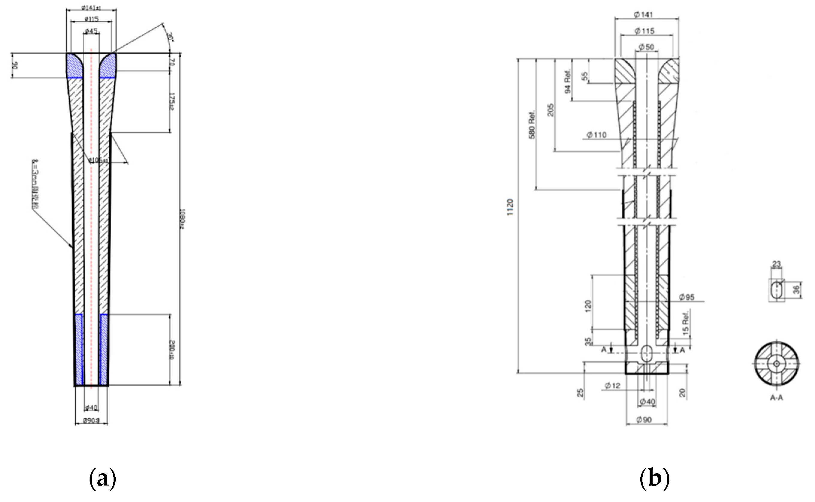
| Immersion depth of straight nozzle (mm) | 100 | Viscosity of molten steel (kg·m−1·s−1) | 0.0055 |
| Immersion depth of five-port nozzle (mm) | 110 | Liquidus temperature of molten steel (K) | 1763 |
| Side holes’ size (mm2) | 23 × 36 | Solidus temperature of molten steel (K) | 1705 |
| Bottom holes’ diameter (mm) | 12 | Specific heat of molten steel (J·kg−1·K−1) | 750 |
| Mold working length (mm) | 635 | Latent heat of molten steel (J·kg−1) | 270,000 |
| Casting speed (m·min−1) | 0.38 | Superheat of straight nozzle, five-port nozzle (K) | 20, 33 |
| Relative permeability of various materials | 1 | Electrical conductivity of molten steel (S·m−1) | 7.14 × 10⁵ |
| Copper mold conductivity (298 K) [16] (S·m−1) | 4.7 × 10⁷ | Copper mold conductivity (423 K) [16] (S·m−1) | 3.18 × 10⁷ |
© 2019 by the authors. Licensee MDPI, Basel, Switzerland. This article is an open access article distributed under the terms and conditions of the Creative Commons Attribution (CC BY) license (http://creativecommons.org/licenses/by/4.0/).
Share and Cite
Wang, P.; Zhang, Z.; Tie, Z.-p.; Qi, M.; Lan, P.; Li, S.-x.; Yang, Z.-b.; Zhang, J.-q. Initial Transfer Behavior and Solidification Structure Evolution in a Large Continuously Cast Bloom with a Combination of Nozzle Injection Mode and M-EMS. Metals 2019, 9, 1083. https://doi.org/10.3390/met9101083
Wang P, Zhang Z, Tie Z-p, Qi M, Lan P, Li S-x, Yang Z-b, Zhang J-q. Initial Transfer Behavior and Solidification Structure Evolution in a Large Continuously Cast Bloom with a Combination of Nozzle Injection Mode and M-EMS. Metals. 2019; 9(10):1083. https://doi.org/10.3390/met9101083
Chicago/Turabian StyleWang, Pu, Zhuang Zhang, Zhan-peng Tie, Meng Qi, Peng Lan, Shao-xiang Li, Zhan-bing Yang, and Jia-quan Zhang. 2019. "Initial Transfer Behavior and Solidification Structure Evolution in a Large Continuously Cast Bloom with a Combination of Nozzle Injection Mode and M-EMS" Metals 9, no. 10: 1083. https://doi.org/10.3390/met9101083
APA StyleWang, P., Zhang, Z., Tie, Z.-p., Qi, M., Lan, P., Li, S.-x., Yang, Z.-b., & Zhang, J.-q. (2019). Initial Transfer Behavior and Solidification Structure Evolution in a Large Continuously Cast Bloom with a Combination of Nozzle Injection Mode and M-EMS. Metals, 9(10), 1083. https://doi.org/10.3390/met9101083