Article

Evaluation of Low Cycle Fatigue Performance of Selective Laser Melted Titanium Alloy Ti–6Al–4V

1
College of Mechanical Engineering, Chongqing University, Chongqing 400044, China
2
State Key Laboratory of Mechanical Transmission, Chongqing University, Chongqing 400044, China
3
College of Engineering, Mathematics and Physical Sciences, University of Exeter, North Park Road, Exeter EX4 4QF, UK
4
School of Advanced Manufacturing Engineering, Chongqing University of Posts and Telecommunications, Chongqing 400065, China
5
College of Mechanical Engineering, Chongqing University of Technology, Chongqing 400054, China
*
Author to whom correspondence should be addressed.
Metals 2019, 9(10), 1041; https://doi.org/10.3390/met9101041
Submission received: 25 August 2019 / Revised: 16 September 2019 / Accepted: 18 September 2019 / Published: 25 September 2019

Abstract

:
The material of Ti–6Al–4V has been widely applied in various industries, such as automobile, aerospace, and medical due to its high specific strength, superior thermal stability and strong corrosion resistance. In the recent decades, selective laser melting (SLM) has become an attractive method to fabricate Ti–6Al–4V parts, thanks to its significant advantages in low material consumption, the high degree of freedom in design, low carbon footprint, etc. Predictability of SLM material fatigue properties is especially important for the safety-critical structures under dynamic load cases. The present research is aimed at evaluating the low cycle fatigue (LCF) performance of SLM Ti–6Al–4V under high loading states. LCF tests were performed for as-built and annealed SLM Ti–6Al–4V. Comparison between LCF properties of SLM Ti–6Al–4V and the wrought Ti–6Al–4V was also made. It was found that as-built SLM Ti–6Al–4V demonstrated a comparable LCF performance with the wrought material. The LCF life of as-built SLM Ti–6Al–4V was longer than that of wrought Ti–6Al–4V at lower strain amplitudes. However, the wrought Ti–6Al–4V had better LCF performance at higher strain amplitudes. The results revealed that the porosity in the as-built SLM material exerted much more impact on the degradation of the material at high strain amplitudes. Annealing deteriorated the LCF performance of SLM Ti–6Al–4V material due to the formation of coarser grains. The cyclic Ramberg–Osgood and the Basquin–Coffin–Manson models were fitted to depict the cyclic stress–strain and the strain–life curves for the SLM Ti–6Al–4V, based on which the LCF performance parameters were determined. In addition, the fatigue fracture surfaces were observed by using scanning electron microscopy (SEM), and the results indicated that fatigue cracks originated from the surface or subsurface defects.

1. Introduction

Selective laser melting (SLM), as an additive manufacturing technology method, focuses on direct transformation and fabrication from a three-dimensional computer-aided design (3D–CAD) model to fully functional ready-to-use metal components [1]. During the SLM process, the metal powder is uniformly spread on the building platform and selectively melted by a high-energy laser beam. After scanning the cross-section of a layer, the platform is lowered by a layer’s thickness, and a new layer is prepared and scanned. This printing process is repeated until the components are completed. With this layer-wise manufacturing approach, the complicated geometries in a component are split into simplified two-dimensional slices. Therefore, SLM provides a promising approach to effectively and efficiently manufacturing innovative products.
Titanium alloys such as Ti–6Al–4V have high specific strength, superior thermal stability, and strong corrosion resistance, and therefore have been widely applied in both aerospace and biomedical industries [2,3]. However, the machinability of titanium alloys is a difficult problem to address based on traditional processing technologies. For instance, when cutting Ti–6Al–4V materials, the traditional manufacturing technologies may cause a few critical problems, such as sticking phenomenon, blade wear-out, and material wastage. Since SLM is the process of joining metal powders, it shows great advantages in fabricating titanium alloy parts while being able to avoid those problems. However, compared to traditional manufacturing technologies, the distinct manufacturing process makes SLM form different microstructures on Ti–6Al–4V parts, and hence different part performance. Therefore, the performance of SLM Ti–6Al–4V components under various monotonous or cyclic loading conditions becomes a critical issue to be investigated. In the literature, this issue has been studied intensively by academic scholars. Some authors in their work [4,5,6] identified that SLM Ti–6Al–4V parts usually consisted of acicular α’ martensite instead of equilibrium α and β phases exhibited in the wrought material and, meanwhile, had higher yield stress, higher ultimate tensile strength, and lower ductility than the wrought material, whereas the residual stresses introduced to the parts could still be effectively eliminated by using traditional post heat treatment (2 h at 800 °C) [7,8]. Some studies investigated the high cycle fatigue (HCF) properties of SLM Ti–6Al–4V material under the elastic deformation scenario incurred by low amplitude cyclic stress. Edwards & Ramulu [9] conducted the HCF tests for SLM Ti–6Al–4V with a load ratio of R = 0.2 at different constant maximum stress levels, from 100 to 600 Mpa. Based on the test results, the authors generated approximate S–N curves for specimens with the different surface condition and build orientation and concluded that the curves for SLM Ti–6Al–4V were significantly lower than that for the wrought material. Xu et al. [10] selected proper SLM processing parameters so that the fatigue life of SLM Ti–6Al–4V samples was able to approach that of the wrought material. Wycisk et al. [11,12] tested the HCF properties for heat-treated (3 h at 600 °C) SLM Ti–6Al–4V samples with different surface conditions (as-built, machined, and shot-peened) and found that the application of machining surface treatment was able to enhance HCF performance to the level of wrought Ti–6Al–4V. Rafi et al. [13] evaluated the SLM Ti–6Al–4V HCF data at a load ratio of R = 0.1, in line with the Metallic Materials Properties Development and Standardization (MMPDS). The results showed that the Ti–6Al–4V specimens fabricated by SLM had a better fatigue performance than the cast. Leuders et al. [14] presented the S–N curves for SLM Ti–6Al–4V in the as-built condition and in different heat treatment conditions. They found that the HCF performance could be optimized through the hot–isostatic–pressing (HIP) treatment with a pressure of 1000 bar and temperature of 920 °C. Kasperovich and Hausmann [15] developed a two-step approach to increasing the HCF resistance of SLM Ti–6Al–4V: firstly, minimizing the inherent defects of SLM Ti–6Al–4V through the optimization of SLM processing parameter, and secondly, adjusting the microstructure of SLM Ti–6Al–4V by appropriate thermal treatment. As a result, the fatigue resistance of SLM Ti–6Al–4V could be comparable with the wrought material. The studies reviewed above investigated the HCF properties for SLM Ti–6Al–4V at low-amplitude cyclic stress level. A few authors [16,17,18] investigated the cyclic elastoplasticity of SLM Ti–6Al–4V during high strain amplitude cycling. From their work, SLM Ti–6Al–4V with α′ martensite presented a much narrower hysteresis loop than that of the wrought bimodal Ti–6Al–4V. However, there are few papers so far which explicitly investigate and evaluate the low cycle fatigue (LCF) performance parameters for SLM Ti–6Al–4V, whereas such research is very important and beneficial to engineering design and operation in practice.
This paper investigated the LCF performance of SLM Ti–6Al–4V materials, in which a set of monotonic tensile tests and strain-controlled LCF tests were performed on both as-built and annealed SLM Ti–6Al–4V samples. The cyclic softening/hardening properties of the SLM Ti–6Al–4V were characterized by stress–strain hysteresis loops and the progression curves of the stress amplitude with cycles. The cyclic stress–strain and strain–life curves of SLM Ti–6Al–4V were fitted according to the Ramberg–Osgood and Basquin–Coffin–Manson models, respectively. In addition, the LCF failure mechanism was analyzed using scanning electron microscopy (SEM). The results were compared with those of the wrought Ti–6Al–4V specimens.

2. Materials and Methods

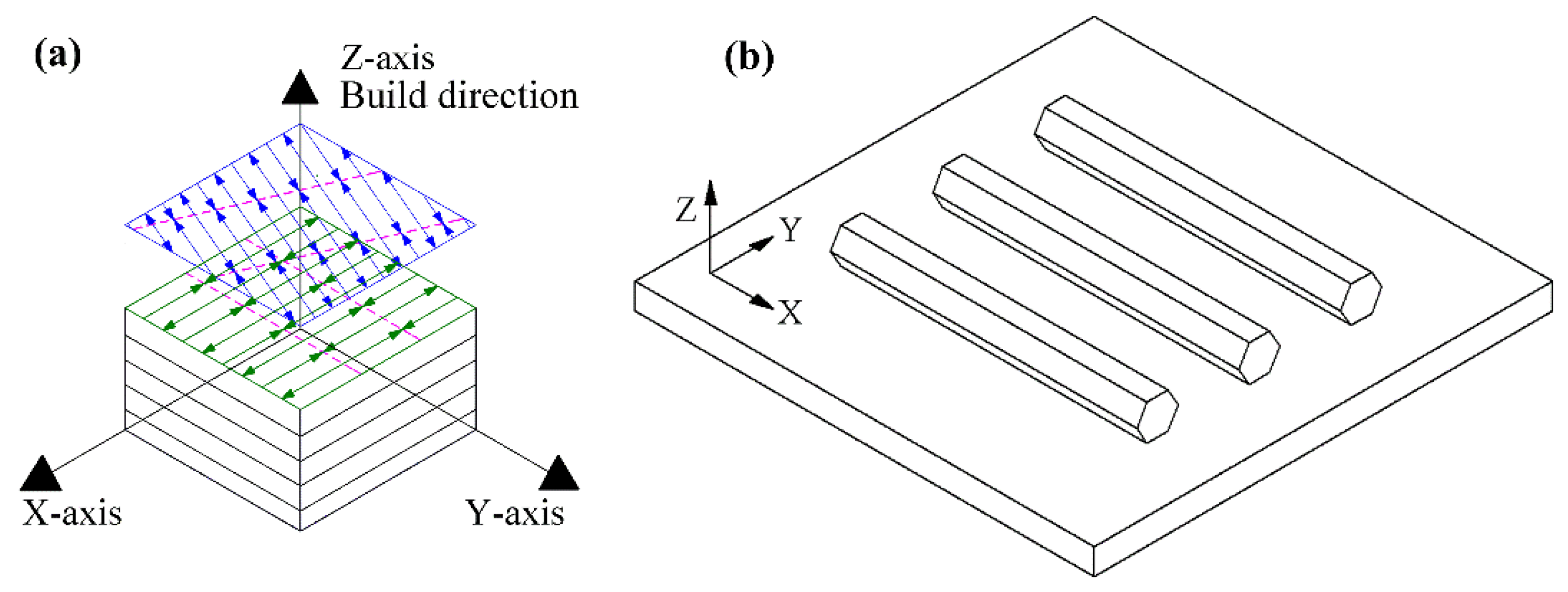
2.1. Selective Laser Melting of Test Samples

In the present study, the printed samples were manufactured by a SLM machine EOSINT M280 using the gas-atomized Ti–6Al–4V powder whose chemical composition content is accordance with the ISO 5832-3, ASTM F1472, and ASTM B348 titanium alloy standards. The chemical composition of the powder is listed in Table 1. To eliminate the Ti–6Al–4V’s oxidation, the oxygen level of the chamber was controlled under 0.1%. In order to avoid curved warping caused by thermal stress, the powder bed was preheated to 35°C. The samples were made based on the EOS recommended SLM processing parameters shown in Table 2. All specimens were printed by using a stripe pattern scanning strategy so as to reduce the thermally induced stresses [19,20]. The rotation angle of the stripe direction is 67° between consecutive layers, as indicated in Figure 1a, which resulted in a more isotropic microstructure and a higher density [21].

2.2. Heat-Treatment and Post-Processing

As shown in Figure 1b, the printed samples are hexagon rods with a length of 120 mm and diameter of the inscribed circle of 13 mm. They were divided into two groups randomly, i.e., the annealed and as-built. Samples in the annealed group were further processed by heat-treatment (800 °C for 2 h) and furnace cooled. All printed samples in the two groups were then machined to LCF test samples as shown in Figure 2. Precisely speaking, on each of test sample, the LCF test was applied in the middle section with a length of 12 mm and diameter of 6mm. To ensure the LCF test quality, the average surface roughness of the test section on each sample was polished to 0.32 μm. In addition, to establish a benchmark for test results comparison and analysis, a group of wrought samples with the identical dimension in Figure 2 were produced.

2.3. Microstructure Observation

Samples in each of three test groups (two SLM-based, one wrought) were randomly selected for microstructure observation by using a Neophot 30 optical microscope (Carl Zeiss, Jena, Germany). For observation, the selected samples were processed through three preparation stages sequentially: grinding, polishing, and etching (1 mL HF + 2 mL HNO3 + 50 mL H2O).

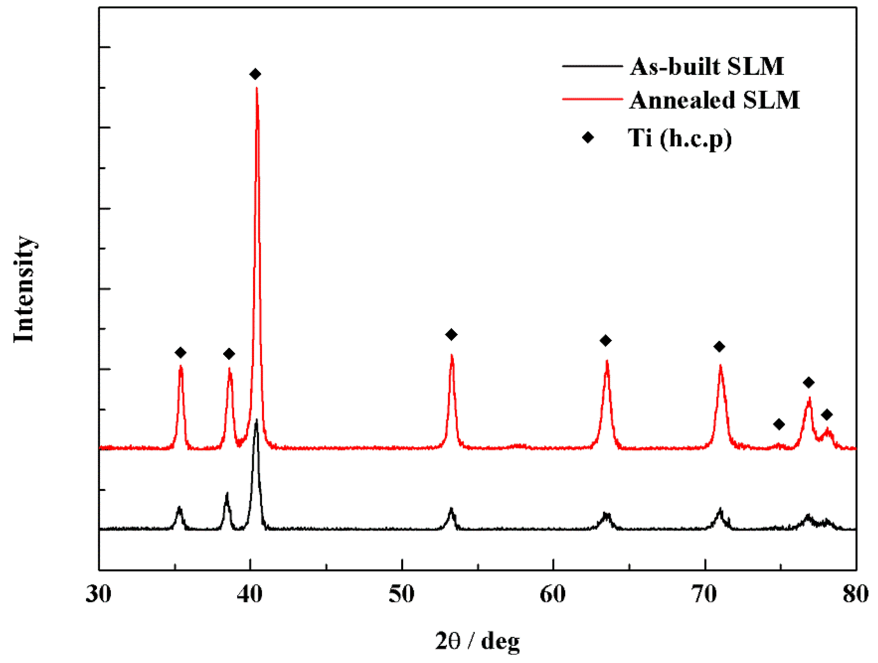
2.4. Phase Identification

Phase analysis was conducted by a D/Max 2500PC X-ray diffraction (XRD) system (Rigaku, Japan) on the as-built and annealed SLM specimens using a Cu Kα-source with a scan speed of 4°/min and a step size of 0.02°.

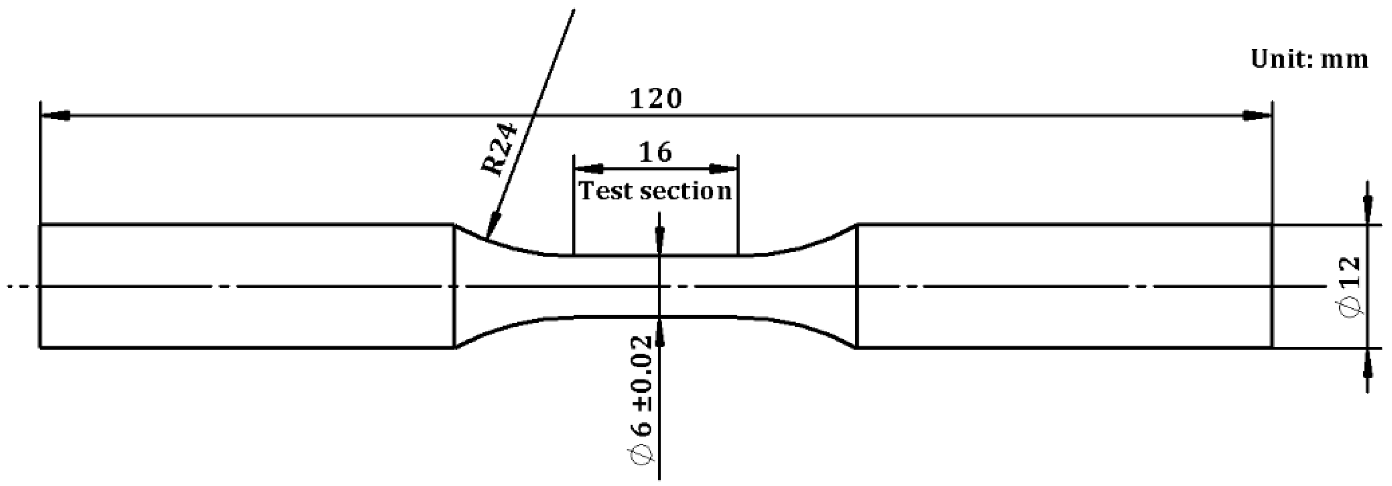
2.5. Monotonic Tension Test

From each of the three groups (two SLM-based, one wrought), three samples were randomly selected, on which tensions tests were conducted in line with the ASTM E8-09 standard. The rate of monotonic tension test was 1 mm/min.

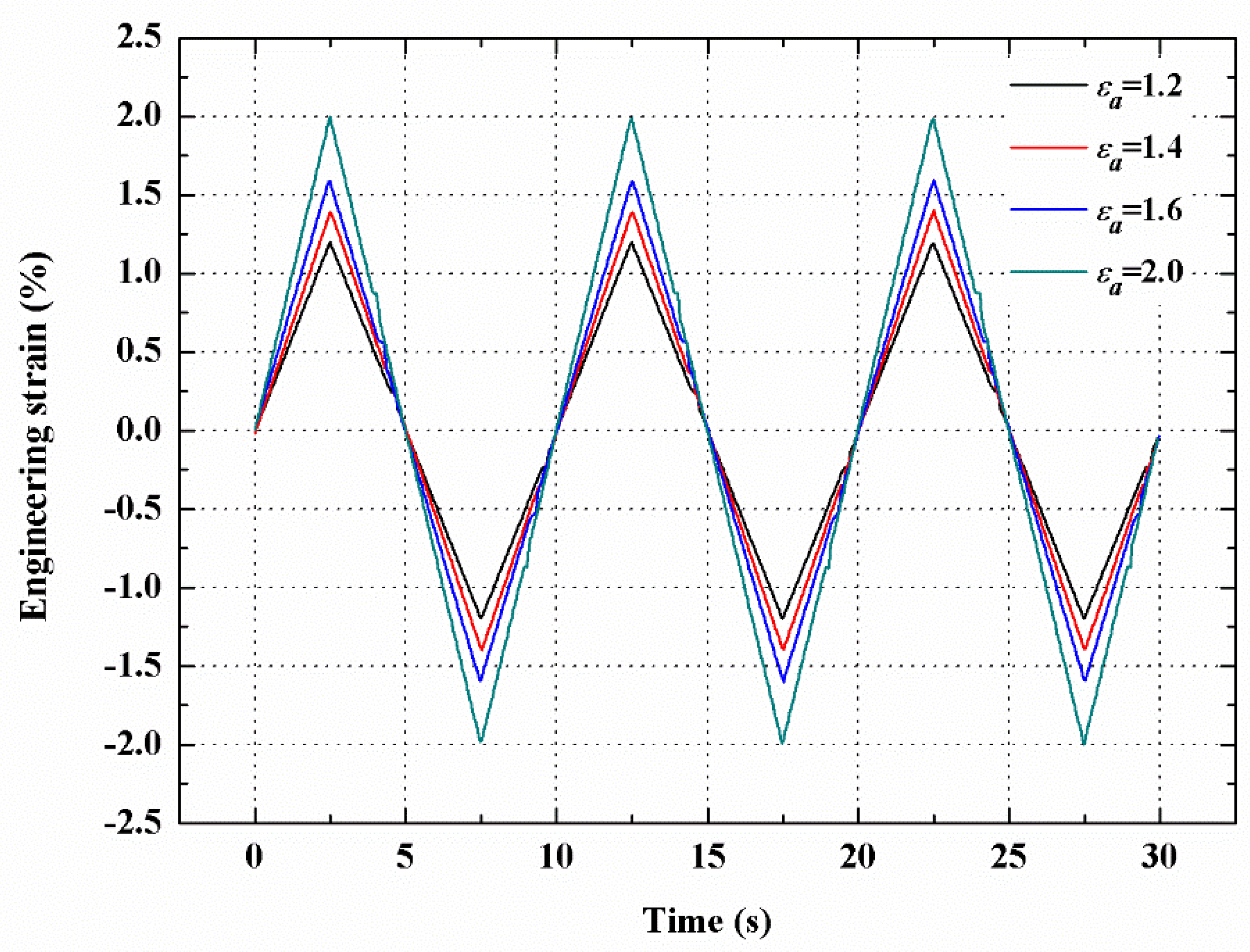
2.6. Low Cycle Fatigue (LCF) Test

Strain-controlled LCF tests were performed under different strain amplitudes ( ε a ) as shown in Table 3. 10 samples were used, including 4 as-built, 4 annealed, and 2 wrought samples. The loading ratio was R = −1. During the test, the strain applied to the test samples was varied by a triangle wave-based control and the frequency was 0.1 Hz, as shown in Figure 3. The experiments were conducted on an MTS 100 kN servo-hydraulic closed-loop test machine (MTS, Eden Prairie, MN, USA) at room temperature. The uniaxial strain was measured by Epsilon 12 mm extensometer with a resolution of 0.1 μm.

2.7. Low Cycle Fatigue (LCF) Fractography Observations

The LCF fractures of SLM samples were analyzed using a TESCAN VEGA SEM (Tescan, Brno, Czech Republic) to investigate the failure mechanism.

3. Results

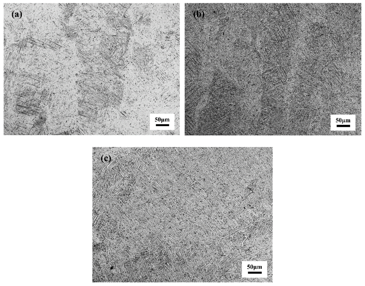
3.1. Initial Microstructure

Figure 4 presents the respective microstructure of the as-built SLM, annealed SLM, and wrought samples before LCF test. Figure 4a indicates that the fine acicular α′ martensite is formed during SLM processing, which results from the alloy’s rapid melt and solidification due to the short interaction between laser and powder and high energy input [5,6,22]. Based on a simulation of the temperature field of SLM processing, Li et al. [23] observed that the cooling rate of Ti–6Al–4V in SLM significantly exceeds the critical cooling rate of 410 K/s required for martensitic transformation (β to α′) of Ti–6Al–4V [24]. The microstructure of annealed samples is shown in Figure 4b, which reveals that the acicular microstructure becomes even coarser than that of the as-built. Compared with needle shape lamellas observed in the SLM samples, the wrought samples have a typical α-β two-phase microstructure, as shown in Figure 4c, wherein the β phases are distributed around the coarse platelet α phases.
Figure 5 shows XRD patterns for as-built and annealed SLM Ti–6Al–4V. All peaks of the two types of samples are characteristic of hexagonal close-packed (hcp) structure of Ti, which indicates that the microstructure is dominated by α′/α phase even after annealing. In this study, the annealing treatment was carried out below β transus temperature and did not result in obvious decomposition of the as-fabricated α′ phase. Therefore, β phase peaks are absent in the annealed SLM Ti–6Al–4V. The peak intensities in the annealed condition are significantly higher compared to the pattern of the as-built conditions, indicating coarser grains in the annealed samples.

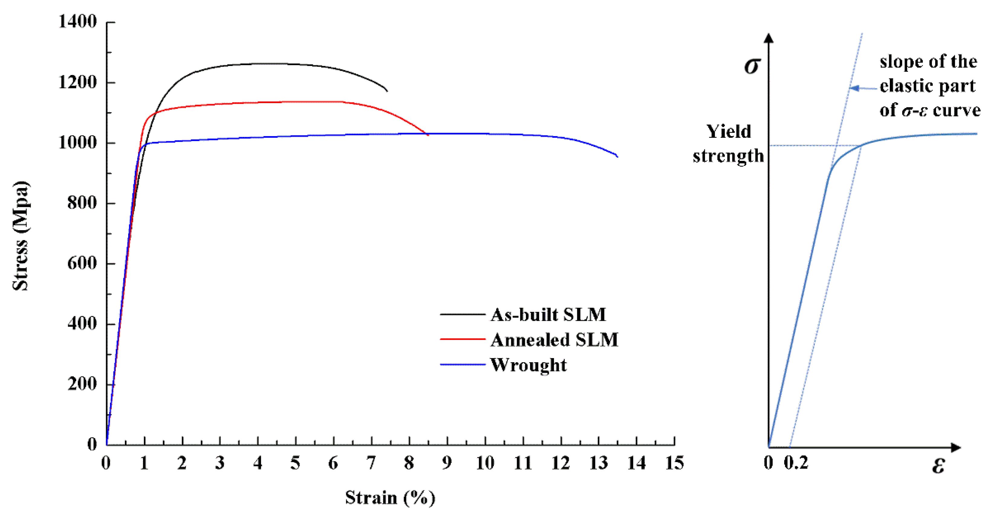
3.2. Monotonic Tensile Test Results

Figure 6 illustrates the monotonic tensile stress–strain curves of the as-built, annealed, and wrought Ti–6Al–4V samples. It is shown that the SLM samples (i.e., as-built and annealed) have a greater ultimate tensile strength and yield strength than the wrought one. The as-built SLM sample shows the highest strength, while the wrought sample has the greatest ductility. The difference in their mechanical performance can be explained by the difference in the microstructure. Amongst the three types of sample, the as-built sample has the smallest grain size, and hence, the largest volume of crystal boundary to prevent alloy dislocation slip resulting in plastic deformation. Therefore, it has the highest tensile strength. After annealing, the grains of the SLM sample are coarsened, and in the context, the tensile strength of the specimens decreased. Low ductility of as-built SLM samples can be improved by increasing the volume fraction of β Ti. However, in this study, the annealing treatment did not result in obvious decomposition of the as-fabricated α′ phase into the α + β phases, therefore, there was a slight change in elongation. As shown in Figure 6, the slopes of elastic deformation stage of stress–strain curves for all three types of sample are approximately equal. This is due to the fact that the elastic modulus mainly depends on the binding force amongst atoms rather than the microstructure. The tension properties of as-built, annealed SLM, and wrought samples are summarized in Table 4. As seen from the results, the ratios between the ultimate tensile strength and the yield strength for the as-built SLM, the annealed SLM, and the wrought samples are about 1.16, 1.05, and 1.03, respectively. All these ratios are less than 1.2, which can indicate that the capability for cyclic strain softening is high [25].

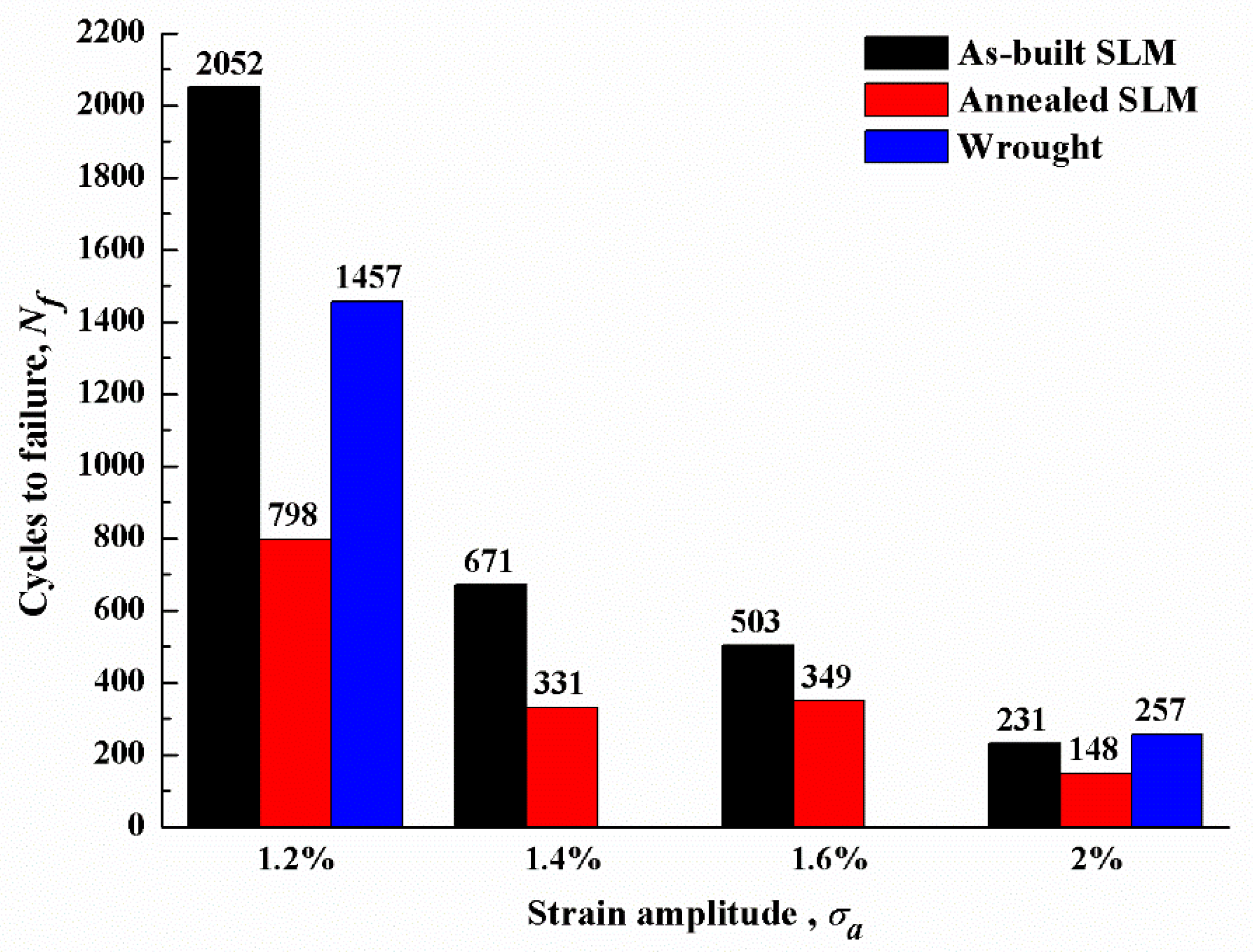
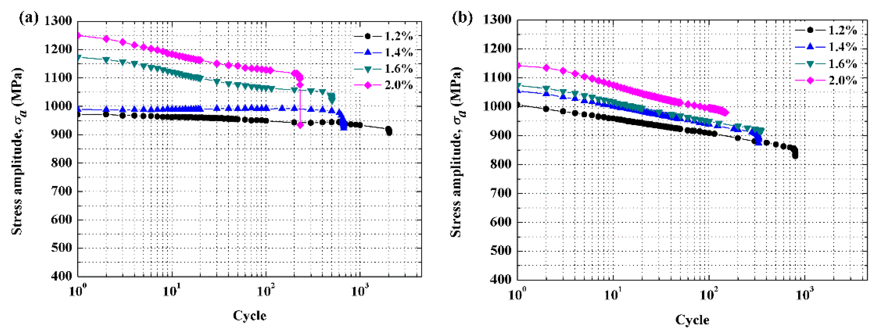
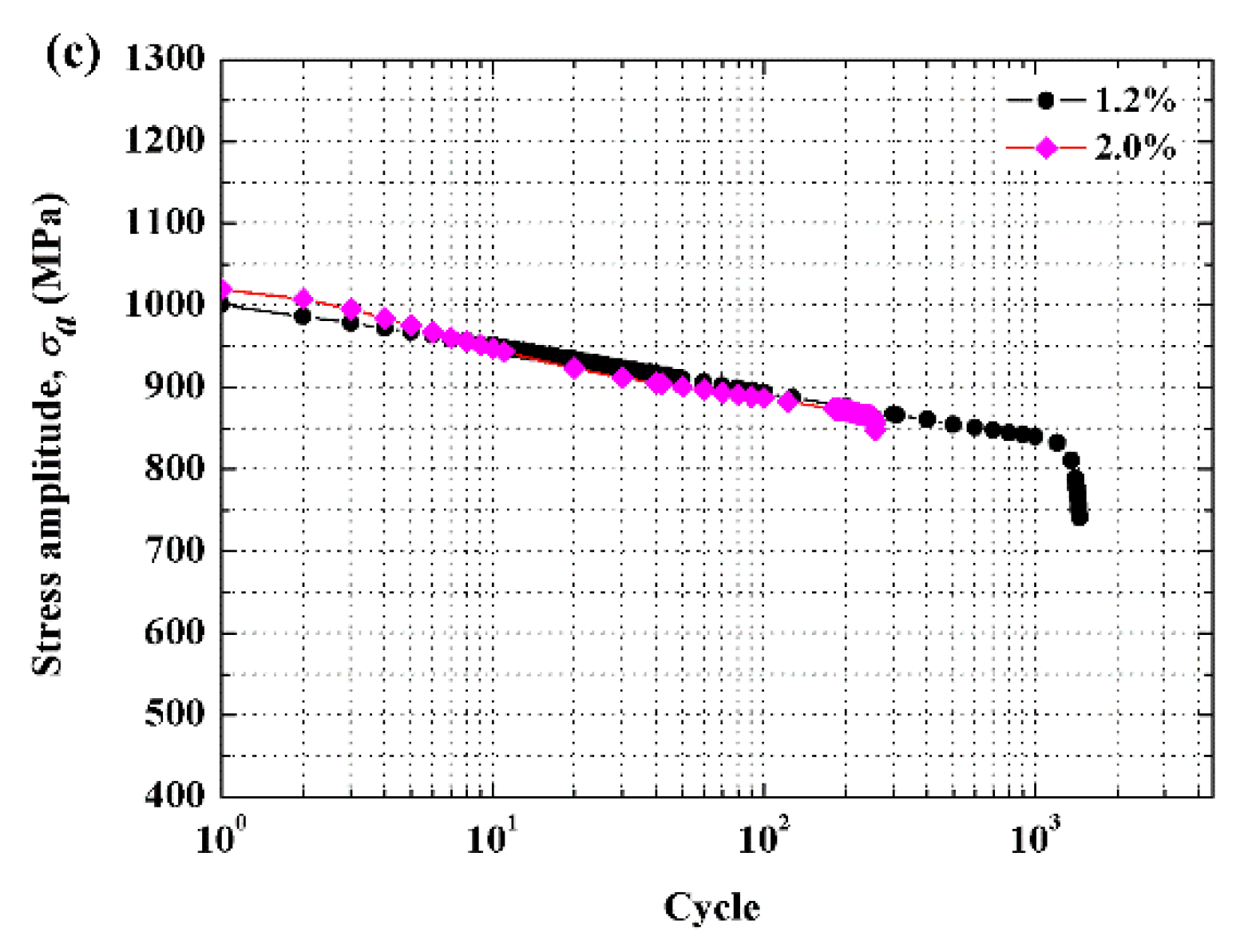
3.3. Low Cycle Fatigue Test Results

Figure 7 shows the LCF life, i.e., Nf, for the three types of samples at different strain amplitudes. As reflected in the figure, Nf declines with the growth of strain amplitude for all types of samples. Under the same strain amplitude level, the as-built SLM sample always has a longer LCF life than the annealed one, because it has a higher strength due to smaller grain structure. Meanwhile, comparing Nf results between the strain amplitude level at 1.2% and 2.0%, it is indicated that the Nf decrement rate of the as-built sample is much higher than that of the wrought sample. This is caused by the pores raised in the SLM process [8,17]. With the increase of strain amplitude level, the porosity of as-built SLM materials exerts a more significant role in the overall degradation of the material [26]. The Nf decrement rate of the annealed SLM samples is lower than that of the as-built, which implies that the coarser grains presented in the annealed SLM microstructure play a more important role in reducing the LCF life of the samples than the porosity.
Figure 8 illustrates the stress–strain responses of the LCF test. In detail, Figure 8a,c,e on the left refer to the hysteresis loops of as-built SLM, annealed SLM, and the wrought samples, respectively, under strain amplitude level at 1.2%, while the figures on the right (see Figure 8b,d,f) represent the respective loops for the samples at 2.0% strain amplitude level. It is implied that the as-built SLM has the smallest plastic deformation during cyclic loading amongst the three types of sample, which further results in the as-built SLM having the most compressed loops amongst the samples. Moreover, it is shown that the SLM samples have a cyclic softening behavior. This proves that there is a correlation between the degree of cyclic softening/hardening and the ratio of the ultimate tensile strength to yield strength for SLM parts. In general, the wrought sample has the largest softening degree, while the degree on the as-built sample is the smallest. At low strain amplitude level (see Figure 8a,c,e), the peak stresses reached in the first cycle for all three types of samples are approximately identical. This is because when the strain level is low, the peak stresses of the samples would not exceed their yield strengths and elastic modulus of three types of samples are approximately equal. On the contrary, at high strain amplitude level, the as-built SLM achieves the greatest peak stress in the first cycle amongst the three types of samples.
Figure 9 demonstrates the stress amplitude variations of the three types of sample alongside the increase of cycles under different strain amplitude levels. The results indicate that for all three types of sample, the cyclic softening is increased alongside the growth of the strain amplitude. Moreover, the as-built SLM Ti–6Al–4V shows the most significant change in cyclic softening amongst the three samples between low and high strain amplitude levels.

4. Discussion

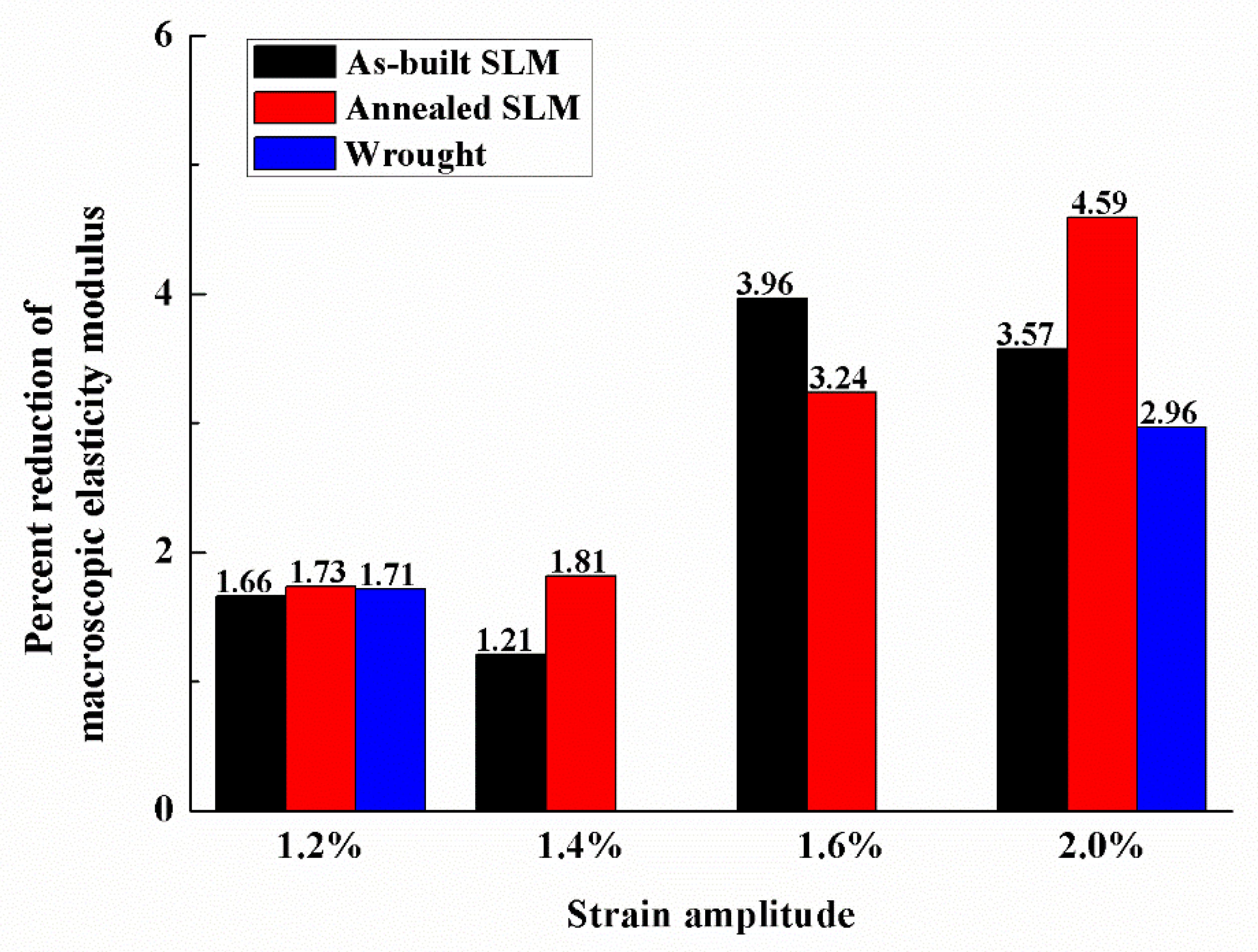
4.1. Variation of the Macroscopic Elasticity Modulus

The reduction in macroscopic elasticity modulus between the first cycle to the half-life for the three types of sample is shown in Figure 10. The macroscopic elasticity modulus was measured as the slope of the linear part of the stress–strain hysteresis loops. In general, there is more reduction in macroscopic elasticity modulus as the strain amplitude increases, which promotes greater cyclic softening in Figure 9. Reductions of macroscopic elasticity modulus are likely related to the decrease of the effective cross-section due to the formation of internal defects [27]. The details of this are necessary to further investigate.

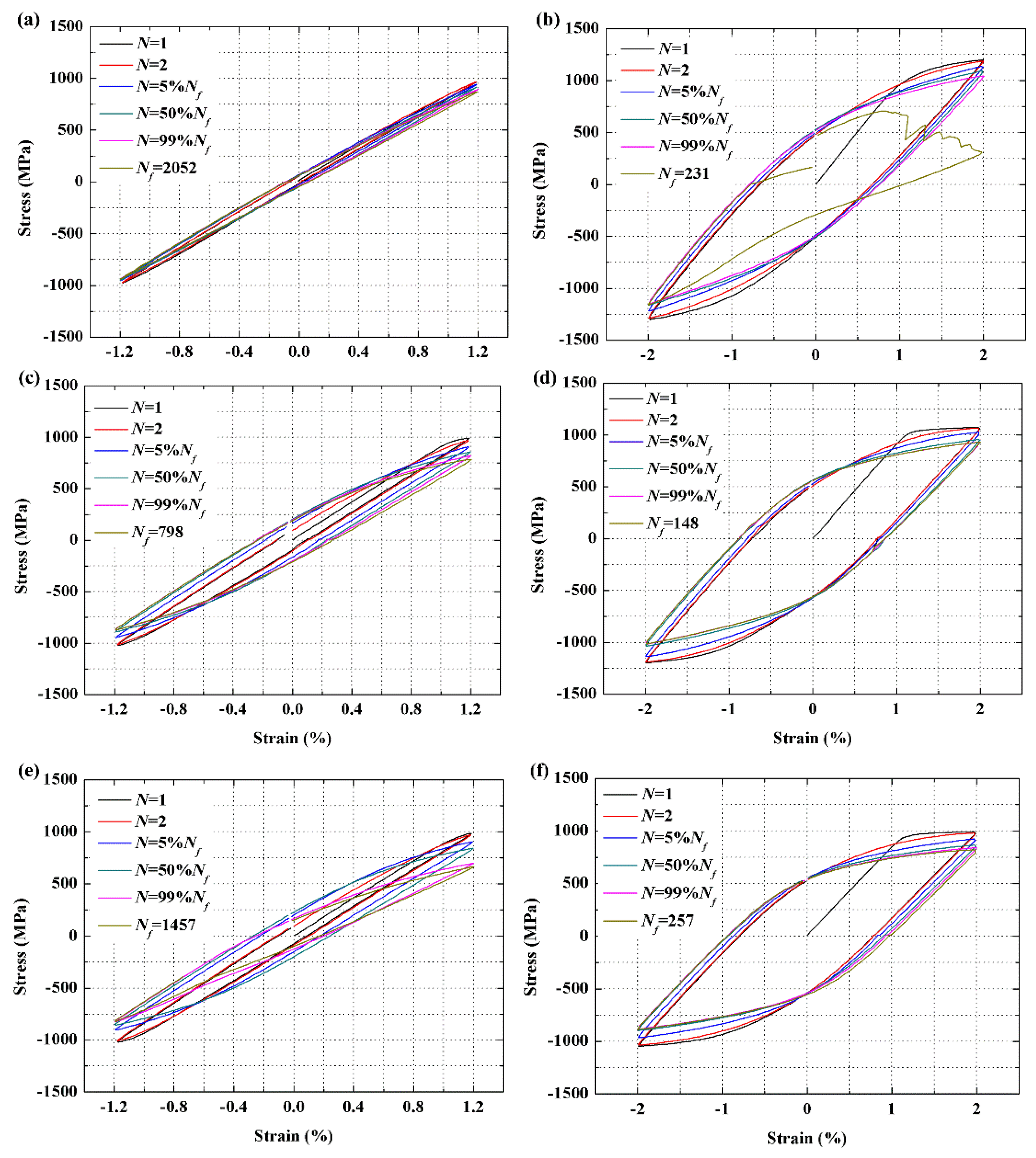
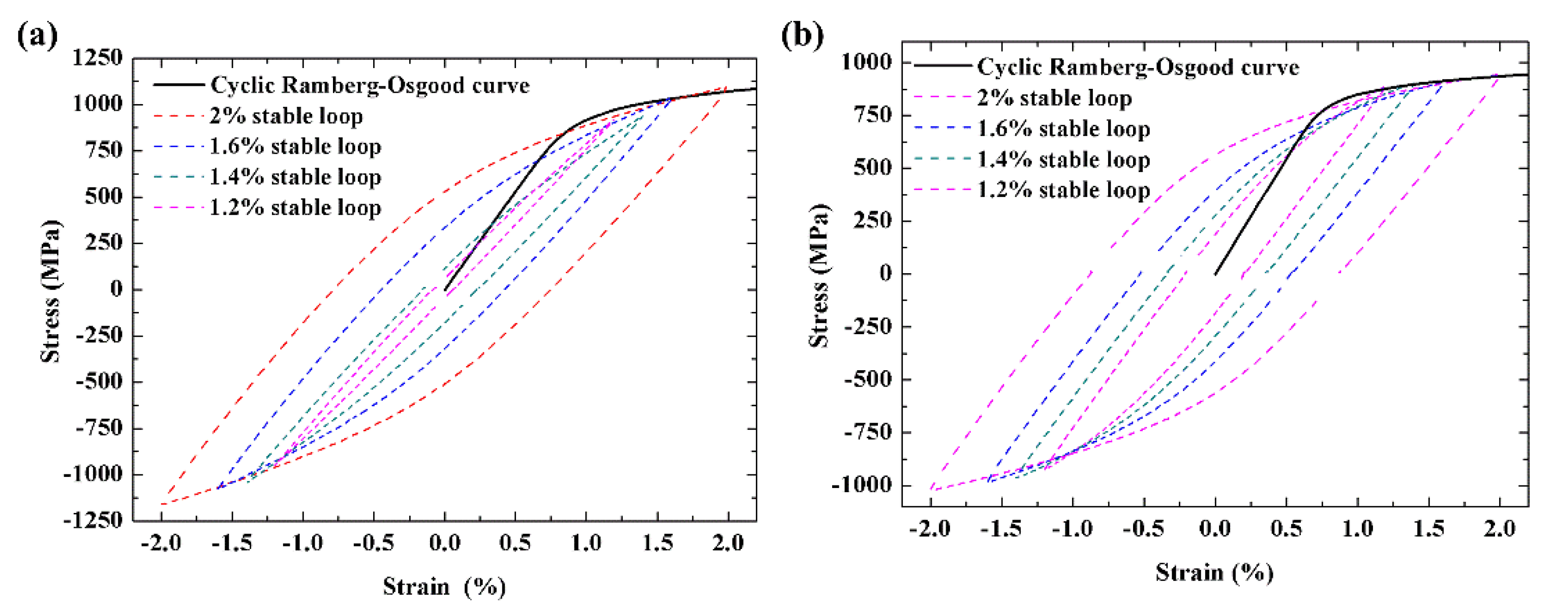
4.2. Cyclic Stress–Strain Curves

Based on the LCF tests under multi-level strain amplitudes, a series of stabilized cyclic stress–strain hysteresis loops at half of the specimen’s life can be obtained. By placing these loops in one reference coordinate system, as shown in Figure 11, the best fit line can be regressed according to the maximum cyclic stresses, which is generally termed as cyclic stress–strain curve and can be modeled in a similar function of monotonic Ramberg–Osgood [28] curve, as shown in Equation (1):
ε a = ε e a + ε p a = σ a E + ( σ a K ) 1 / n
where ε e a and ε p a refer to elastic and plastic components of strain amplitude, respectively, K′ denotes the cyclic strength coefficient, n′ is the strain cyclic hardening exponent, and E is the elastic modulus. The ε p a part in the above equation can be expressed in a linear format in Equation (2) when making a logarithmic transformation on both sides.
n   lg ε p a + lg K = lg σ a
The parameters of the cyclic Ramberg–Osgood model for the SLM Ti–6Al–4V are shown in Table 5.

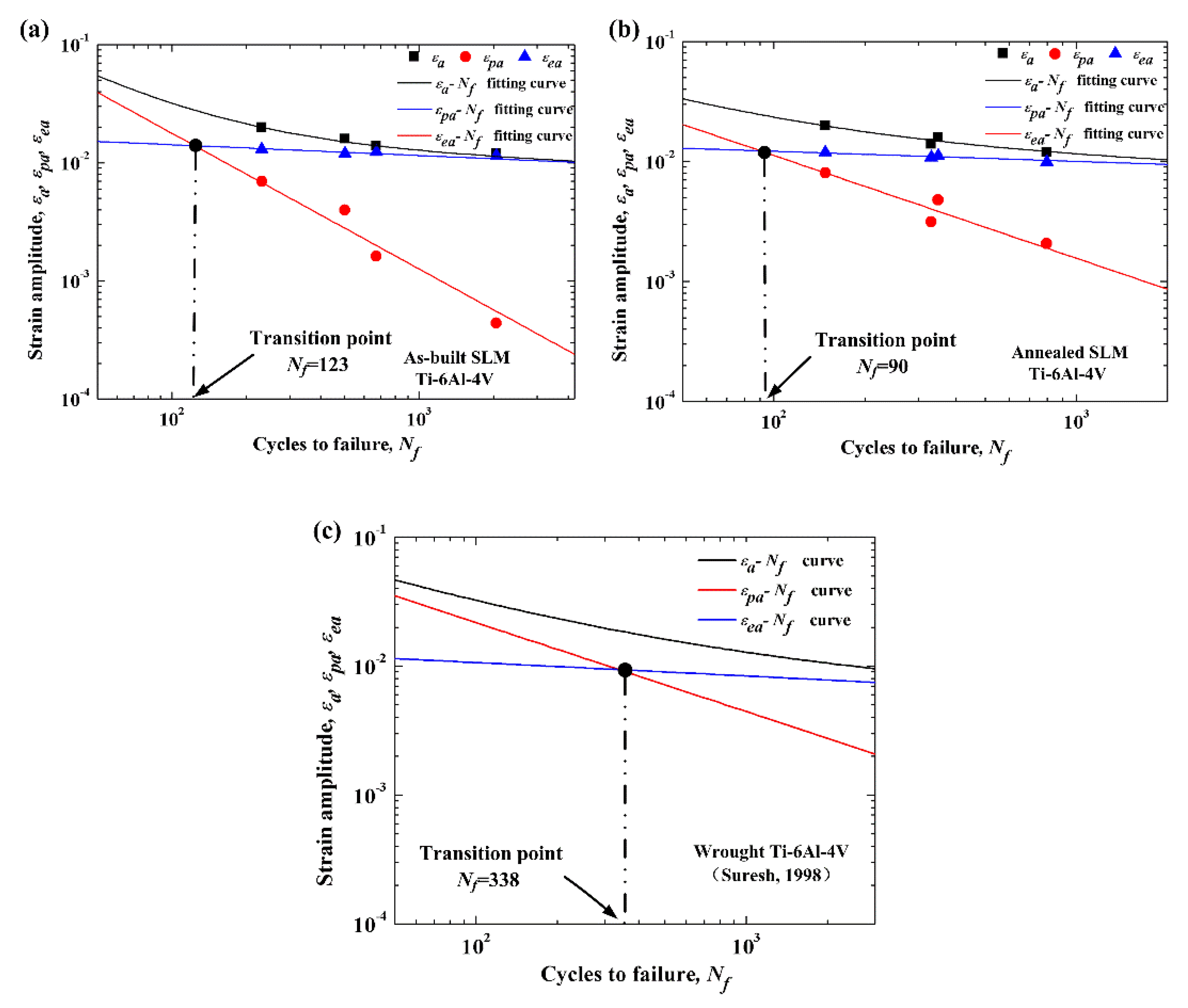
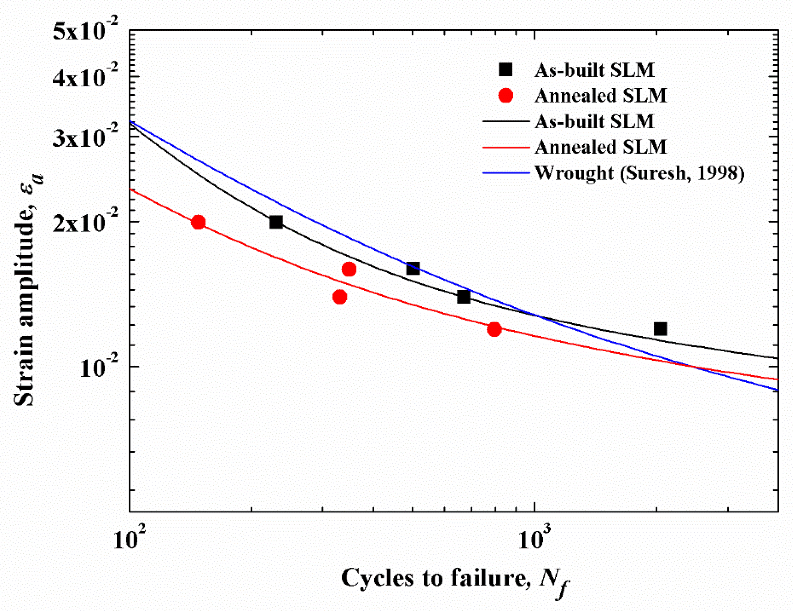
4.3. Strain–Life Curves

The local approach is one of the typical fatigue design methods, and it is adopted in low cycle conditions to estimate the crack formation duration, which is generally conducted on the basis of strain–life curves. The strain–life curves can be approximately described by the Basquin–Coffin–Manson relation using a power function [29,30,31,32] given in Equation (3):
ε a = σ f E ( 2 N f ) b + ε f ( 2 N f ) c
where σ f and ε f are the fatigue strength and ductility coefficients, respectively, and b and c are the fatigue strength and ductility exponents, respectively. The two parts on the right side of Equation (3) represent the elastic and plastic strain amplitudes, which are expressed in Equations (4) and (5), respectively:
ε e a = σ f E   ( 2 N f ) b
ε p a = ε f ( 2 N f ) c
When making logarithmic operations on both sides, they can become linear as well. Based on the LCF test results, the strain–life curves for as-built and annealed SLM are plotted in Figure 12a,b, respectively. In each figure, the curve illustrates the relationship between total strain amplitude ε a , and the fatigue life Nf, while the relationships of ε ea - N f and ε p a - N f are represented by the two straight lines which are obtained by using the least square regression method. The fatigue strength and fatigue ductility parameters of the Basquin–Coffin–Manson equation for the SLM Ti–6Al–4V are then calculated based on the regression lines, which are given in Table 6. For the analysis reference, the relevant curves for the wrought Ti–6Al–4V are cited from the study in Reference [32], shown in Figure 12c. It is reflected from Figure 12a,b that the transition lives of the as-built and annealed SLM Ti–6Al–4V occur at approximately 100 cycles. This implies that the LCF life of the SLM Ti–6Al–4V above 100 cycles is governed by elastic strain rather than plastic strain. Therefore, the LCF behavior of SLM Ti–6Al–4V is dominated by fatigue strength rather than fatigue ductility properties. However, the wrought material has a larger number of transition life than the SLM Ti–6Al–4V, which is approximately 338 cycles, as exhibited in Figure 12c. Therefore, plastic deformation has more great fatigue damage for the SLM material than for the wrought material. Figure 13 depicts a comparison of the total strain amplitude life of the SLM against the wrought Ti–6Al–4V. It is observed that the fatigue performance of the as-built SLM Ti–6Al–4V is at a similar level to the wrought material, and the annealed SLM Ti–6Al–4V has the worst fatigue performance amongst the three types of materials. Compared to the wrought material, the as-built SLM Ti–6Al–4V has a better fatigue performance at low levels of strain amplitude, but a worse LCF performance when the strain amplitude is high. This is because, under the small strain amplitude levels, the peak cyclic stress is close to the yield stress, and hence strain hardening has a significant effect on material deformation. As the strain amplitude increase, the plastic deformation mechanisms play a more important role, and the porosity in the as-built SLM material exerted much more impact on the overall degradation of the material.

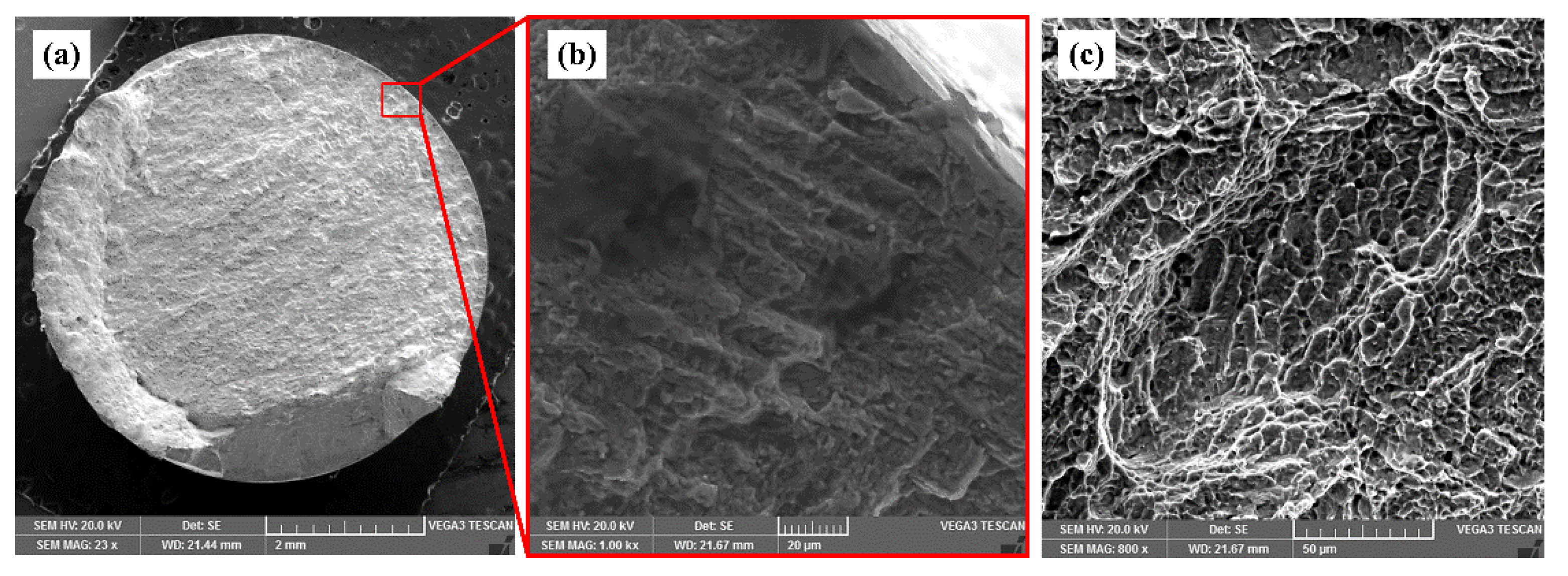
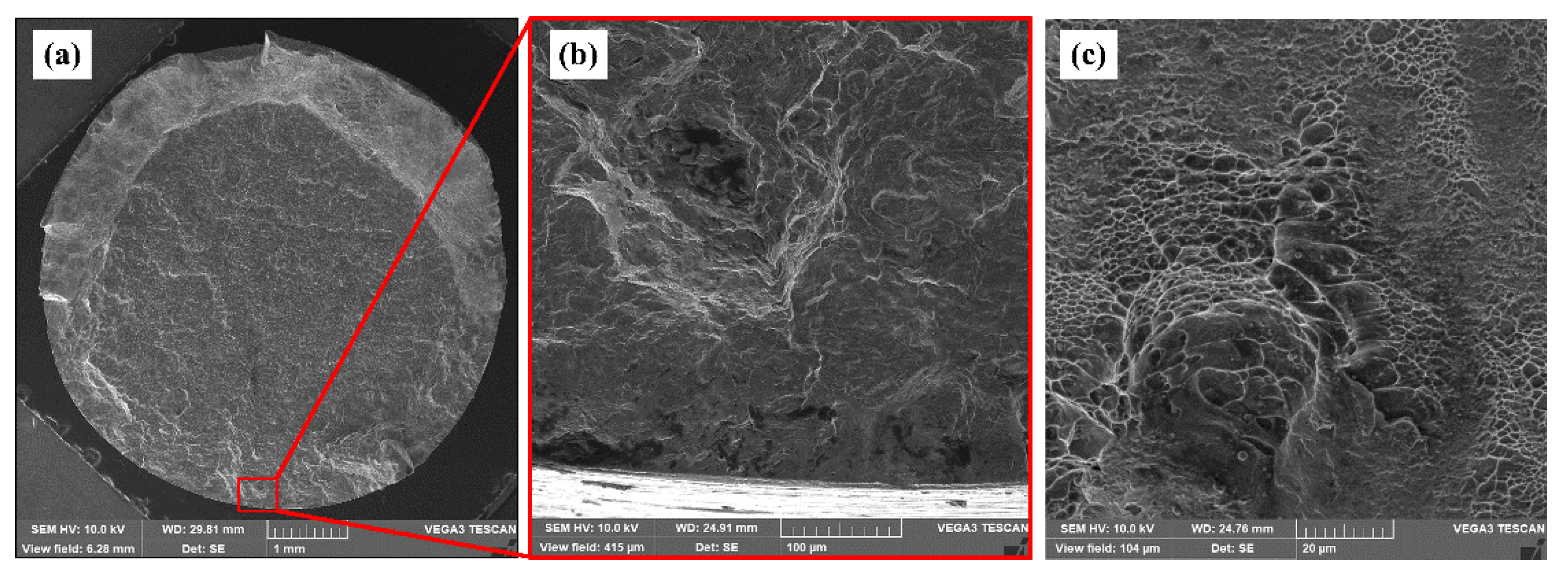
4.4. Low Cycle Fatigue (LCF) Fractography

In general, fatigue damage to metal material has three stages: the crack initiation caused by local plastic stress concentration, the crack propagation in the way of microcracks interconnection, and the instantaneous rupture taking place when crack propagation reaches a critical threshold. Ti–6Al–4V fabricated by SLM exhibits the same LCF failure mechanism as other metal materials. In all the fatigue test samples, the cracks always initiated from the surface or subsurface defects. SEM micrographs of LCF fracture surface for as-built SLM Ti–6Al–4V tested at 1.2% strain amplitude are given in Figure 14. In Figure 14a,b, fatigue cracks start from the surface and propagate to the inside. During crack propagation, fatigue striations are generated, which are generally adjacent to the area of the crack initiation. Figure 15 shows the LCF fracture surface of the as-built sample tested at 2.0% strain amplitude. In Figure 15a,b, a pore located about 120 μm below the surface can be noticed, which contributes to the crack initiation. Cyclic stresses are applied to both surface and interior of the samples simultaneously. The stress applied to the surface tends to be higher than that applied to the interior area. Meanwhile, in the internal area, every grain is surrounded by others, while the grains on the surface area have fewer border constraints formed by the surrounding and, hence, slip easily. In addition, machine traces and scratches result in stress concentration on the surface area and then accelerate the crack initiation. Besides, it has been proven that the pores near to surface have higher stress concentration and act as potential crack initiation sites [33,34]. The final rupture regions are shown in Figure 14c and Figure 15c. It can be seen that the instantaneous rupture surfaces contain dimples which are characteristic of the static load fracture.

5. Conclusions

This paper investigated the microstructures, monotonic tension, cyclic stress–strain behavior, and LCF properties of the as-built and annealed SLM Ti–6Al–4V. The conclusions of the study are drawn as follows:
  • The as-built SLM Ti–6Al–4V consisted of fine acicular α’ martensite, therefore displayed the higher strength and lower ductility than the wrought material, whereas after being annealed, the tensile strength of Ti–6Al–4V decreased, which mainly resulted from the coarsened grains formed during the annealing process.
  • Cyclic softening behavior was observed for both as-built and annealed SLM Ti–6Al–4V. With the growth of strain amplitude level, more elasticity modulus reductions occurred during the cyclic loading, which promoted a greater cyclic softening.
  • The cyclic Ramberg–Osgood and the Basquin–Coffin–Manson models were fitted to depict the cyclic stress–strain and the strain–life curves for the SLM Ti–6Al–4V, respectively. The parameters of LCF performance for SLM Ti–6Al–4V were then determined based on the fitted curves, which could be used in fatigue simulation analysis of SLM Ti–6Al–4V parts in real cases.
  • This paper showed that the as-built SLM Ti–6Al–4V had a comparable LCF performance to the wrought material. Compared to the wrought material, the as-built SLM material had better fatigue performance at low strain amplitudes but a worse LCF performance at high strain amplitudes, which is because that porosity in the as-built SLM material exerted much more impact on the overall degradation of the material at high strain amplitude levels. However, the annealing treatment caused SLM Ti–6Al–4V to have coarser grains and hence deteriorated LCF performance. To avoid grain growth while eliminating the residual stresses, the appropriate heat treatment process for SLM Ti–6Al–4V parts is worthy of being be investigated in future research.
  • It was observed that fatigue cracks always initiated from the surface or subsurface defects. Instantaneous rupture region exhibited the characteristics of the static load fracture.

Author Contributions

Conceptualization, D.Z., A.N.H and P.Z.; Methodology, P.Z., F.L. and K.Z.; Investigation, P.Z., F.L. and J.J.; Writing—original draft preparation, P.Z.; Writing—review and editing, A.N. and D.Z.Z

Funding

This research was supported by the National High Technology Research and Development Program of China (863 Program: 2015AA042501).

Acknowledgments

The authors acknowledge the financial support from the National High Technology Research and Development Program of China (863 Program: 2015AA042501).

Conflicts of Interest

The authors declare no conflict of interest.

References

  1. Gu, D.D.; Meiners, W.; Wissenbach, K.; Poprawe, R. Laser additive manufacturing of metallic components: Materials, processes and mechanisms. Int. Mater. Rev. 2013, 57, 133–164. [Google Scholar] [CrossRef]
  2. Boyer, R.R. An Overview on the Use of Titanium in the Aerospace Industry. Mater. Sci. Eng. A 1996, 213, 103–114. [Google Scholar] [CrossRef]
  3. Niinomi, M. Mechanical biocompatibilities of titanium alloys for biomedical applications. J. Mech. Behav. Biomed. Mater. 2008, 1, 30–42. [Google Scholar] [CrossRef] [PubMed]
  4. Xu, W.; Brandt, M.; Sun, S.; Elambasseril, J.; Liu, Q.; Latham, K.; Xia, K.; Qian, M. Additive manufacturing of strong and ductile Ti–6Al–4V by selective laser melting via in situ martensite decomposition. Acta Mater. 2015, 85, 74–84. [Google Scholar] [CrossRef]
  5. Vrancken, B.; Thijs, L.; Kruth, J.-P.; Van Humbeeck, J. Heat treatment of Ti6Al4V produced by Selective Laser Melting: Microstructure and mechanical properties. J. Alloy. Compd. 2012, 541, 177–185. [Google Scholar] [CrossRef] [Green Version]
  6. Vilaro, T.; Colin, C.; Bartout, J.D. As-Fabricated and Heat-Treated Microstructures of the Ti–6Al–4V Alloy Processed by Selective Laser Melting. Metall. Mater. Trans. A 2011, 42, 3190–3199. [Google Scholar] [CrossRef]
  7. Mercelis, P.; Kruth, J.-P. Residual stresses in selective laser sintering and selective laser melting. Rapid Prototyp. J. 2006, 12, 254–265. [Google Scholar] [CrossRef]
  8. Leuders, S.; Thöne, M.; Riemer, A.; Niendorf, T.; Tröster, T.; Richard, H.; Maier, H.J. On the mechanical behaviour of titanium alloy TiAl6V4 manufactured by selective laser melting: Fatigue resistance and crack growth performance. Int. J. Fatigue 2013, 48, 300–307. [Google Scholar] [CrossRef]
  9. Edwards, P.; Ramulu, M. Fatigue performance evaluation of selective laser melted Ti–6Al–4V. Mater. Sci. Eng. A 2014, 598, 327–337. [Google Scholar] [CrossRef]
  10. Xu, W.; Sun, S.; Elambasseril, J.; Liu, Q.; Brandt, M.; Qian, M. Ti–6Al–4V Additively Manufactured by Selective Laser Melting with Superior Mechanical Properties. JOM 2015, 67, 668–673. [Google Scholar] [CrossRef]
  11. Wycisk, E.; Emmelmann, C.; Siddique, S.; Walther, F. High Cycle Fatigue (HCF) Performance of Ti–6Al–4V Alloy Processed by Selective Laser Melting. Adv. Mater. Res. 2013, 816–817, 134–139. [Google Scholar] [CrossRef]
  12. Wycisk, E.; Solbach, A.; Siddique, S.; Herzog, D.; Walther, F.; Emmelmann, C. Effects of Defects in Laser Additive Manufactured Ti-6Al-4V on Fatigue Properties. Phys. Procedia 2014, 56, 371–378. [Google Scholar] [CrossRef] [Green Version]
  13. Rafi, H.K.; Starr, T.L.; Stucker, B.E. A comparison of the tensile, fatigue, and fracture behavior of Ti–6Al–4V and 15-5 PH stainless steel parts made by selective laser melting. Int. J. Adv. Manuf. Technol. 2013, 69, 1299–1309. [Google Scholar] [CrossRef]
  14. Leuders, S.; Lieneke, T.; Lammers, S.; Tröster, T.; Niendorf, T. On the fatigue properties of metals manufactured by selective laser melting—The role of ductility. J. Mater. Res. 2014, 29, 1911–1919. [Google Scholar] [CrossRef]
  15. Kasperovich, G.; Hausmann, J. Improvement of fatigue resistance and ductility of TiAl6V4 processed by selective laser melting. J. Mater. Process. Technol. 2015, 220, 202–214. [Google Scholar] [CrossRef]
  16. Kourousis, K.; Agius, D.; Wang, C.; Subic, A. Constitutive Modeling of Additive Manufactured Ti-6Al-4V Cyclic Elastoplastic Behaviour. Tech. Mech. 2016, 36, 47–62. [Google Scholar]
  17. Phaiboonworachat, A.; Kourousis, K. Cyclic Elastoplastic Behaviour, Hardness and Microstructural Properties of Ti-6Al-4V Manufactured through Selective Laser Melting. Int. J. Mater. Eng. Innov. 2016, 7, 80–87. [Google Scholar] [CrossRef]
  18. Agius, D.; Kourousis, K.I.; Wallbrink, C.; Song, T. Cyclic plasticity and microstructure of as-built SLM Ti–6Al–4V: The effect of build orientation. Mater. Sci. Eng. A 2017, 701, 85–100. [Google Scholar] [CrossRef]
  19. Emmelmann, C.; Kranz, J.; Herzog, D.; Wycisk, E. Laser Additive Manufacturing of Metals. In Laser Technology in Biomimetics; Springer: Berlin/Heidelberg, Germany, 2013; pp. 143–162. [Google Scholar]
  20. Matsumoto, M.; Shiomi, M.; Osakada, K.; Abe, F. Finite element analysis of single layer forming on metallic powder bed in rapid prototyping by selective laser processing. Int. J. Mach. Tools Manuf. 2002, 42, 61–67. [Google Scholar] [CrossRef]
  21. Thijs, L.; Verhaeghe, F.; Craeghs, T.; Humbeeck, J.V.; Kruth, J.-P. A study of the microstructural evolution during selective laser melting of Ti–6Al–4V. Acta Mater. 2010, 58, 3303–3312. [Google Scholar] [CrossRef]
  22. Qiu, C.; Adkins, N.J.E.; Attallah, M.M. Microstructure and tensile properties of selectively laser-melted and of HIPed laser-melted Ti–6Al–4V. Mater. Sci. Eng. A 2013, 578, 230–239. [Google Scholar] [CrossRef]
  23. Li, Z.; Xu, R.; Zhang, Z.; Kucukkoc, I. The influence of scan length on fabricating thin-walled components in selective laser melting. Int. J. Mach. Tools Manuf. 2018, 126, 1–12. [Google Scholar] [CrossRef]
  24. Ahmed, T.; Rack, H. Phase transformations during cooling in α+β titanium alloys. Mater. Sci. Eng. A 1998, 243, 206–211. [Google Scholar] [CrossRef]
  25. Smith, R.W.; Hirschberg, M.H.; Manson, S. Fatigue Behavior of Materials under Strain Cycling in Low and Intermediate Life Range; National Aeronautics and Space Administration Cleveland Oh Lewis Research Center: Cleveland, OH, USA, 1963.
  26. Gribbin, S.; Bicknell, J.; Jorgensen, L.; Tsukrov, I.; Knezevic, M. Low cycle fatigue behavior of direct metal laser sintered Inconel alloy 718. Int. J. Fatigue 2016, 93, 156–167. [Google Scholar] [CrossRef]
  27. Lemaitre, J.; Chaboche, J.-L. Mechanics of Solid Materials; Cambridge University Press: Cambridge, UK, 1990. [Google Scholar]
  28. Osgood, W.R.; Ramberg, W. Description of Stress-Strain Curves by Three Parameters; National Advisory Committee for Aeronautics: Washington, DC, USA, 1943; pp. 1–13. [Google Scholar]
  29. Basquin, O.H. The Exponential Law of Endurance Testing. Am. Soc. Test. Mater. 1910, 19, 625–630. [Google Scholar]
  30. Manson, S.S. Behavior of Materials Under Conditions of Thermal Stress; Technical Report TN 2933; NACA: Boston, MA, USA, 1953. [Google Scholar]
  31. Coffin, L.F., Jr. A Study of the Effects of Cyclic Thermal Stresses on a Ductile Metal. Trans. Am. Soc. Mech. Eng. 1954, 76, 931–950. [Google Scholar]
  32. Suresh, S. Fatigue of Materials, 2nd ed.; Cambridge University Press: Cambridge, UK, 1998. [Google Scholar]
  33. Siddique, S.; Imran, M.; Rauer, M.; Kaloudis, M.; Wycisk, E.; Emmelmann, C.; Walther, F. Computed tomography for characterization of fatigue performance of selective laser melted parts. Mater. Des. 2015, 83, 661–669. [Google Scholar] [CrossRef]
  34. Fatemi, A.; Molaei, R.; Sharifimehr, S.; Phan, N.; Shamsaei, N. Multiaxial fatigue behavior of wrought and additive manufactured Ti-6Al-4V including surface finish effect. Int. J. Fatigue 2017, 100, 347–366. [Google Scholar] [CrossRef]
Figure 1. (a) Scanning strategy used to produce test specimens and (b) Hexagonal rods orientations on the selective laser melting (SLM) build-platform for the low cycle fatigue (LCF) tests.
Metals 09 01041 g001
Figure 2. The low cycle fatigue (LCF) test specimen geometry.
Metals 09 01041 g002
Figure 3. Strain–time waveforms of low cycle fatigue testing.
Metals 09 01041 g003
Figure 4. Microstructure of (a) as-built selective laser melting (SLM), (b) annealed SLM, and (c) wrought Ti–6Al–4V specimens.
Metals 09 01041 g004
Figure 5. X-ray diffraction (XRD) patterns of as-built and annealed selective laser melting (SLM) Ti–6Al–4V samples.
Metals 09 01041 g005
Figure 6. The monotonic stress–strain curves of Ti–6Al–4V.
Metals 09 01041 g006
Figure 7. Number of cycles to failure (Nf) for low cycle fatigue (LCF) for the samples of Ti–6Al–4V.
Metals 09 01041 g007
Figure 8. Stress–strain hysteresis loops for as-built samples for strain amplitude of (a) 1.2% and (b) 2%, annealed samples for strain amplitude of (c) 1.2% and (d) 2% and wrought samples for strain amplitude of (e) 1.2% and (f) 2%.
Metals 09 01041 g008
Figure 9. Stress amplitude σ a variations for (a) as-built selective laser melting (SLM), (b) annealed SLM, and (c) wrought samples at different strain amplitude levels.
Metals 09 01041 g009aMetals 09 01041 g009b
Figure 10. Variation (change between first cycle to the half-life) of the macroscopic elasticity modulus for the LCF Ti–6Al–4V specimens.
Metals 09 01041 g010
Figure 11. The cyclic Ramberg–Osgood model fit of the measured data for (a) as-built SLM Ti–6Al–4V and (b) annealed SLM Ti–6Al–4V.
Metals 09 01041 g011
Figure 12. (a) The Basquin–Coffin–Manson model fit of the measured data for the as-built selective laser melting (SLM) Ti–6Al–4V; (b) The Basquin–Coffin–Manson model fit of the measured data for the annealed SLM Ti–6Al–4V; (c) The total, plastic, elastic strain–life curves for wrought Ti–6Al–4V (data refer from Reference [32]).
Metals 09 01041 g012
Figure 13. The total strain–life curves for selective laser melting (SLM) Ti–6Al–4V tested here compared to the data of wrought Ti–6Al–4V (data refer from Reference [32]).
Metals 09 01041 g013
Figure 14. Scanning electron microscopy (SEM) micrographs of low cycle fatigue (LCF) fracture surface for as-built selective laser melting (SLM) Ti–6Al–4V tested at strain amplitude of 1.2%: (a) macro–fractograph, (b) crack initiation and propagation from the surface, and (c) final rupture region.
Metals 09 01041 g014
Figure 15. Scanning electron microscopy (SEM) micrographs of low cycle fatigue (LCF) fracture surface for as-built selective laser melting (SLM) Ti–6Al–4V tested at strain amplitude of 2.0%: (a) macro–fractograph, (b) crack initiation site, and (c) final rupture region.
Metals 09 01041 g015
Table 1. The chemical compositions and their contents in the powder.
Chemical ElementWeight/%Atom/%
Al K5.709.72
Ti K90.7687.09
V K3.533.19
Total100
Table 2. Selective laser melting (SLM) processing parameters for Ti–6Al–4V samples.
Laser Power (W)Scanning Speed (mm/s) Hatching Space (μm)Layer Thickness (mm)
17012501000.03
Table 3. Strain amplitudes ε a in (%) of low cycle fatigue (LCF) testing.
As-Built SLMAnnealed SLMWrought
222
1.61.6-
1.41.4-
1.21.21.2
Table 4. Tensile properties of Ti–6Al–4V.
Ti–6Al–4VElastic Modulus (GPa)Tensile Strength (MPa)Yield Strength (MPa)Elongation to Failure (%)
As-built selective laser melting (SLM) 106 ± 31262 ± 131084 ± 226.2 ± 1.5
Annealed SLM 109 ± 41137 ± 111088 ± 97.1 ± 2
Wrought111 ± 21030 ± 17997 ± 1012.5 ± 1.6
Table 5. Parameters of the cyclic Ramberg–Osgood model for the SLM Ti–6Al–4V.
Ti–6Al–4Vn’K’
As-built0.078331535.15
Annealed0.059861222.59
Table 6. Parameters of the Basquin–Coffin–Manson model for the selective laser melting (SLM) and wrought Ti–6Al–4V.
Ti–6Al–4VE (GPa) σ f (MPa)b ε f c
As-built SLM1062452.03−0.091657.7848−1.14246
Annealed SLM1092017.46−0.084281.0541−0.85695
Suresh, 1998 [32]1102030−0.1040.841−0.69

