Abstract
Producing joints of aluminum and copper by means of fusion welding is a challenging task. However, the results of various studies have proven the potential of friction stir welding (FSW) for manufacturing aluminum-copper joints. Despite the proven feasibility, there is currently no series application in automotive industry to produce aluminum-copper joints for electrical contacts by means of FSW. To make FSW as efficient as possible for large-scale production, maximized welding speed is desired. Taking this into account, this paper presents results of a parametric investigation, the objective of which was to increase the welding speed for FSW of aluminum and copper in comparison to welding speeds that are considered to be state of the art. Taguchi method was used to design an experimental plan and target figures of the investigations were the resultant tensile strengths and electrical resistances. Dependencies between input parameters and target figures were determined systematically. The optimal welding parameters, at which joints failed in the weaker aluminum material, included a welding speed of 700 mm/min. Consequently, it could be shown that joints with a performance similar to those of the base materials can be obtained using significantly higher welding speeds than reported in the relevant literature.
1. Introduction
Excellent electrical and thermal conductivity combined with high ductility, creep resistance and corrosion resistance are the reasons for copper materials being considered to be state of the art in current-carrying components for automotive applications. However, using copper is disadvantageous regarding the high procurement costs and the high material density. Taking this into account, dissimilar aluminum-copper joints represent a solution with great potential for weight and cost-optimized conductors [1,2]. In order to produce joints for electrical contacts, it is well-known that firmly bonded joining is preferred to interlocking and force-locking joining techniques, due to better electrical performance of the joint [3]. However, joining aluminum and copper is a challenging task by means of conventional fusion welding. Different melting temperatures of the base materials, the high thermal conductivities, and the low mutual solubility, which leads to the formation of brittle intermetallic phases, make it difficult to achieve sound welds [4]. Instead, joining processes in which the formation of a melt is avoided are receiving much interest [5]. Friction stir welding (FSW) also belongs to these so-called solid state joining techniques and various authors report on the suitability of this process for joining aluminum and copper materials [2,6,7,8,9,10].
FSW was developed and patented in 1991 by Thomas et al. [11]. In order to perform a firmly bonded joint, this process uses a non-consumable tool, which typically consists of a shoulder and a pin. This rotating tool is pressed into the joint gap and then traversed along the joint line. As a result of tool rotation and feed, the two joining partners are plasticized and stirred [12].
Most studies carried out in the field of FSW of aluminum and copper provide proof of feasibility and focus on the influence of tool and process parameters on the resulting mechanical and microstructural joint properties. Important findings have been obtained through the work of Xue et al. [9] and Akinlabi [7]. These authors inform unanimously on the importance of positioning the harder copper material on the advancing side (AS) and the softer aluminum workpiece on the retreating side (RS) in order to manufacture sound welds free of defects. Moreover, a lateral offset towards the softer aluminum material is recommended to improve the material flow, and thus, the weld quality. Further publications on FSW of aluminum and copper are summarized in Table 1. All of these literature references report on the successful joining of aluminum and copper using FSW.

Table 1.
Overview of previous studies on dissimilar FSW of aluminum and copper.
Despite the proven potential, as far as the authors of this study know, there is currently no series application in the automotive industry to produce aluminum-copper joints for electrical contacts by means of FSW. In order to achieve this, there are several aspects that require further investigation. This study addresses a research questions that is of particular relevance to the use of FSW for the production of aluminum-copper joints in the automotive industry. As can be seen in Table 1, FSW in previous research studies has been conducted at relatively low welding speeds. The objective of this work is to determine a significantly higher welding speed than in published studies, at which butt welds with excellent mechanical and electrical performance can be manufactured in order to make the FSW process as efficient as possible for large-scale production.
2. Materials and Methods
The applied materials in this study were EN AW-1050A and EN CW004A. Table 2 shows the chemical compositions of both materials, which were taken from the material supplier. The dimensions of the blanks were 160 mm, 100 mm, and 3 mm (length, width, thickness). The FSW experiments were performed on a PTG Powerstir portal system (PTG Heavy Industries Ltd, West Yorkshire, UK) in position-controlled operation. The clamping setup used for fixation of the blanks is shown in Figure 1. The FSW tool used for the welding tests was made of heat treated steel (X40CrMoV5-1) and consisted of a flat shoulder with a diameter of 18 mm and an unthreaded pin with a diameter of 6 mm. The length of the variably adjustable pin was set to 2.9 mm. All the friction stir welds produced within this study had a length of 120 mm.
Table 2.
Chemical compositions of the applied base materials [18,19].
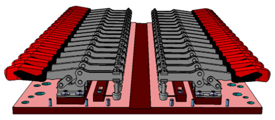
Figure 1.
Clamping setup used for FSW experiments.
In order to increase the welding speed in comparison to published studies in the field of Al-Cu FSW, it was necessary to consider a wider parameter window for the parametric investigation. Design of experiments (DoE) was used to ensure an efficient procedure in terms of test effort and quality of results. Using the statistics software Minitab 18 (Minitab GmbH, Munich, Germany), an experimental plan was created. This was a fractional factorial Taguchi L25 design with three factors and five levels. Taguchi orthogonal plans are known to be suitable for parameter optimization purposes. The process parameters that were kept constant during the welding tests are listed in Table 3. The plunge depth and the tool tilt angle were determined based on preliminary tests and were not varied during the welding tests in order to achieve a complete penetration depth. As recommended by Xue et al. [9] and Akinlabi [7], the copper workpiece was positioned on the AS throughout the investigations.
Table 3.
Constant process parameters for the welding experiments.
The process parameters, hereinafter also referred to as factors, which were varied equidistantly during the parametric investigation, are the traverse speed (factor 1), the tool rotation speed (factor 2), and the offset towards the aluminum side (factor 3). The structure of the Taguchi L25 design with 25 individual experiments is shown in Table 4, and the levels for each process parameter are listed in Table 5. For statistical purposes, three samples were welded for each factor-level combination.
Table 4.
Structure of Taguchi L25 design with three factors and five levels.
Table 5.
Factors and their levels.
The evaluation of joint quality for the individual factor-level combinations was carried out by means of tensile testing and electrical resistance measurement. Moreover, hardness tests and metallographic analyses were performed on selected samples by digital microscopy and scanning electron microscopy (SEM) to assess the quality of the welds.
The tensile tests were conducted according to DIN EN ISO 25239-5 [20] by the test machine Zwick Z100 (Zwick GmbH & Co. KG, Ulm, Germany) at an operating speed of 10 mm/min. Transversal sections of the friction stir welds were detached by water jet cutting for evaluation of the mechanical joint properties. In order to avoid excessive material consumption, a distance of 20 mm from the plunging spot has been set for detaching the samples. This distance deviates from the 50 mm specified in DIN EN ISO 25239-5 [20]. The shape of the samples for tensile testing accorded with DIN EN ISO 4136 [21]. In addition to the friction stir welds, five samples each of the respective base materials were tensile tested.
For analyzing the electrical joint properties, the four point resistance measurement setup that is shown in Figure 2 was applied. This setup consists of the Micro-Ohmmeter MR5-600 (Schuetz Messtechnik GmbH, Teltow, Germany) and a clamping device that was designed for the rectangular samples with widths of 40 mm and lengths of 190 mm. A test current of 200 A was chosen and the measuring tips had a distance of 30 mm. The used setup allowed the measurement of the electrical resistance of the weld seam and the respective base materials simultaneously. The electrical resistance of the copper base material was measured via measuring tips 1 and 2, and the aluminum base material was analyzed via measuring tips 3 and 4. The welded area was positioned between tips 2 and 3. For each of the three areas ten values were recorded that were averaged subsequently.
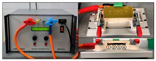
Figure 2.
Four point resistance measurement setup.
The samples for digital microscopy were prepared using the standard metallographic procedures. After mounting, the samples were ground using 1200 SiC abrasive paper and then polished using 1 µm aluminum oxide suspension and 50 nm colloidal silica suspension. Grinding and polishing were done manually to avoid the shifting of aluminum particles into the copper side and vice versa. A digital microscope VHX-2000 (Keyence Deutschland GmbH, Neu-Isenburg, Germany) was used to analyze the metallographic features of the friction stir welds.
The samples for scanning electron microscopy were mounted, ground with 1200 and 2400 SiC abrasive papers, and then polished with 6 µm, 3 µm, and 1 µm diamond suspension. This procedure prevented topographical differences at the Al-Cu interfaces, so that the relevant areas could be analyzed properly. Scanning electron microscope model Scios (Field Electron and Ion Company, Hillsboro, OH, USA) was used for further analysis of the Al-Cu interfaces by means of backscattered electrons (BSE).
Vickers hardness tests were carried out using the Leco AMH-43 test device (Leco Corporation, Saint Joseph, MO, USA) with a test load of 0.1 kp.
Once the optimal FSW parameters had been determined, the scalability of the results was tested. Since the ratio of tool rotation speed to traverse speed is a key figure for the heat input in FSW, these parameters were scaled up, while the optimal ratio that was determined through the parametric investigation was kept constant. The motivation for these experiments was a further increase in welding speed.
In order to be able to compare the properties of the friction stir welds to those of the respective base materials, the base materials are characterized at first. Five tensile specimens were tested per base material. Moreover, the electrical properties of the base materials were analyzed using the four point resistance measurement method. The measured values of the 75 samples from the parametric investigation were used for both base materials.
The last part of this section describes the labelling of the samples. Table 6 includes all the different variants.
Table 6.
Tabular list of material and specimen labeling.
3. Results and Discussion
3.1. Mechanical and Electrical Properties of the Base Materials
Table 7 provides an overview on the mean values and standard deviations of the tensile strengths and the electrical resistances of the base materials used.
Table 7.
Tensile strength and electrical resistance of the base materials used.
3.2. Mechanical and Electrical Properties of the Al-Cu Friction Stir Welds
The evaluation of the welding experiments for parameter optimization starts with analyzing the mechanical properties of the friction stir welds for the different factor-level combinations (Figure 3). The diagram shows that the averaged tensile strength for parameter settings 1, 6, 22, and 23 is at the level of the aluminum base material. For three of the four parameter combinations mentioned, failure in all tensile specimens occurred in the weaker aluminum base material, which is always the objective when welding dissimilar joints. However, it was observed that most specimens failed in the area of the weld seam. This leads to the conclusion that the parameter window for the production of welds with optimal tensile strength is relatively small.
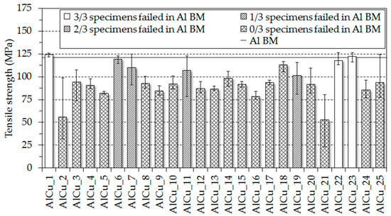
Figure 3.
Tensile strengths of the friction stir welds from the Taguchi experimental plan.
In order to be able to compare the heat input between different welds, the ratio between tool rotation speed and traverse speed (n/v-ratio) will be used in the following. This n/v-ratio indicates the number of revolutions per mm feed, and thus, allows a rough estimation of the heat input [22]. Low heat input is represented by a low n/v-ratio and a high n/v-ratio stands for high heat input into the workpieces. Throughout the welding experiments, the n/v-ratio was in a range from 0.15 1/mm to 1.2 1/mm. Taking into account that the n/v-ratios for the parameter settings that lead to the highest tensile strengths are comparatively low, with values of 0.4 1/mm (AlCu_1), 0.29 1/mm (AlCu_6), 0.23 1/mm (AlCu_22), and 0.31 1/mm (AlCu_23), it can be concluded that cold welding tends to lead to better mechanical properties.
Figure 3 also shows that the tensile strengths of samples that were produced with parameter settings AlCu_5, AlCu_9, AlCu_13, AlCu_17, and AlCu_21 are amongst the lowest values. All of these parameter settings included an offset of 3.0 mm into the aluminum side. Since the tool pin has a diameter of 6 mm, no scratching of the copper workpiece should have taken place, leading to an insufficient material mixing. Consequently, the joint strength can only be attributed to an adhesive bonding of the base materials. In order to follow up this consideration, further examination is given in Section 3.5 by means of metallographic analyses.
The results of the electrical resistance measurements are given in Figure 4. The diagram shows that the averaged electrical resistances for the 25 parameter combinations are at a level of approximately 5.7 µΩ. Since this value corresponds to the resistance average of both base materials, it can be concluded that the mass proportions of aluminum and copper in the joining area are balanced and that welds with excellent current-carrying behavior have been produced. This observation confirms a good choice of the considered parameter window for the experimental design.
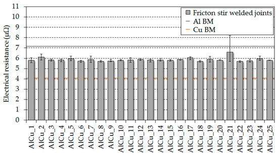
Figure 4.
Electrical resistances of the friction stir welds from the Taguchi experimental plan.
A comparison of the results for tensile testing with electrical resistance measurements shows that the electrical resistances are subject to significantly lower deviations than the resultant tensile strength. Consequently, it is evident that the target figure electrical resistance is more robust against parameter changes than the tensile strengths of the friction stir welds.
3.3. Analysis of the Taguchi Experimental Plan
After the tensile strengths and the electrical resistances of the friction stir welds from the Taguchi experimental plan have been compared with each other and initial dependencies have been identified, the influence of each factor on the respective target figure is presented by the main effect plots in Figure 5.
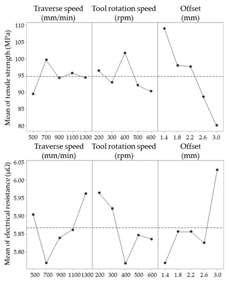
Figure 5.
Main effect plots for mean of tensile strength and mean of electrical resistance.
From the main effect plots for the target figure tensile strength it can be seen that only the offset has a steady influence, whereby the tensile strength decreases with larger offsets. In contrast, the traverse speed and the tool rotation speed do not have a steady effect on the tensile strength. Due to the fact that the joint properties, and thus, also the tensile strength depend essentially on the heat input and the associated n/v-ratio during FSW, the effect of the factors traverse speed and tool rotation speed are difficult to separate from each other clearly. Instead, the interaction of these two factors, which is expressed by the n/v-ratio, is crucial for the joint quality. Consequently, no clear correlation between traverse speed and tensile strength or tool rotation speed and tensile strength results from the main effect plots. However, it should be noted that the most powerful levels for these two parameters (traverse speed 700 mm/min and tool rotation speed 400 rpm) result in a n/v-ratio of 0.57 1/mm. This value is relatively low compared to the highest n/v-ratio from the Taguchi experimental plan (1.2 1/mm). Hence, the observation that relatively cold welds achieve better tensile strengths could be confirmed by the main effect plots.
In accordance with the main effect plots for the target figure tensile strength, the main effect plots for the mean of electrical resistance also show a steady influence from the offset and an unsteady influence from the factors traverse speed and tool rotation speed. In addition, it can be seen that for all three factors the courses for the tensile strength are nearly contrary to those for the electrical resistance. Since each tensile strength maximum results in a minimum electrical resistance, the following optimal welding parameters can be considered to maximize the tensile strength, and at the same time minimize the electrical resistance of the friction stir welds.
- Traverse speed: 700 mm/min
- Tool rotation speed: 400 rpm
- Offset 1.4 mm:
3.4. Scaling of Optimal Welding Parameters
In order to verify the optimal welding parameters to maximize the tensile strength and minimize the electrical resistance, which were determined by the analysis of the Taguchi experimental plan, welding tests were carried out using these parameter settings. Since the aim of the parametric investigation is to maximize the welding speed, further welding experiments were performed. Therefore, the factors traverse speed and tool rotation speed were scaled up, while maintaining the n/v-ratio of 0.57 1/mm and using a constant offset of 1.4 mm. Table 8 gives an overview on the parameter combinations used. Three welds were produced per parameter setting.
Table 8.
Parameter combinations for welding experiments with optimal n/v-ratio.
The tensile strengths and electrical resistances resulting from these parameter settings are presented in Figure 6. The diagram shows that only parameter combination AlCuopt_1 leads to tensile strengths on the level of the aluminum base material. The average tensile strength for this parameter set is even higher, by 1.98 Mpa, than that for the most effective factor-level-combination from the Taguchi experimental design (AlCu_1). Also, the resulting electrical resistance for parameter combination AlCuopt_1 is by 0.03 µΩ lower than that for the most low-resistant parameter combination from the Taguchi experimental design (AlCu_22). The conclusion is that the optimal welding parameters determined by the main effect diagrams could be verified.
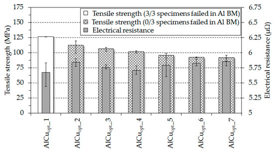
Figure 6.
Tensile strengths and electrical resistances for welding experiments with optimal n/v-ratio.
On the other side, it can be seen that scaling up the traverse speed and the tool rotation speed leads to an almost linear decrease in tensile strength and to an increase in electrical resistance. Therefore, it is evident that scaling up these parameters is not feasible without a loss in joint quality.
However, based on the welding experiments carried out within this study, it was proved that significantly higher welding speeds than those specified in the state of the art can be achieved.
3.5. Metallographic Analysis of the Al-Cu Friction Stir Welds and Hardness Testing
In order to be able to understand the observations made in the previous subsections, metallographic analyses were carried out on selected specimens.
The first objective within this subsection is to explain why welds with lower offset lead to higher weld quality. Then, it is to be shown why parameter settings that represent lower heat input achieve friction stir welds with better tensile strengths. In addition, the reduced joint qualities when scaling up the factors traverse speed and tool rotation speed while maintaining the optimal n/v-ratio will be discussed.
As could be determined during the evaluation of the mechanical and electrical joint properties and the analysis of the Taguchi experimental plan, both the tensile strength and the electrical resistance are clearly dependent on the choice of the offset. Considering the macrostructures shown in Figure 7, it can be seen that the quantity as well as the size of copper particles stirred into the aluminum side vary depending on the chosen offset. Furthermore, it can be seen from the figure that with an offset of 3 mm there was no scratching of the copper through the tool pin. As a result, no copper particles were stirred into the aluminum side. These findings lead to the conclusion that more intense material mixing, which is achieved by smaller offsets, leads to better electrical and mechanical properties. However, it should be said that as shown by Xue et al. [9] and Akinlabi [7], the offset should not be too small to ensure a beneficial material flow.
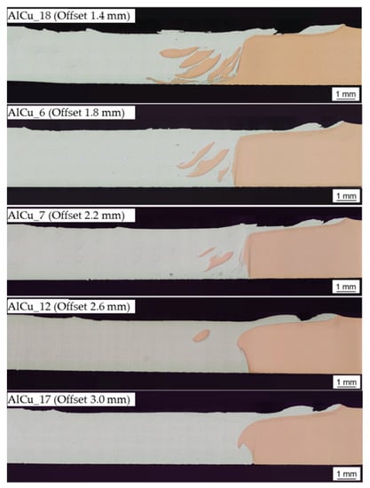
Figure 7.
Cross-sectional macrostructures of Al-Cu friction stir welds produced using parameter settings AlCu_18, AlCu_6, AlCu_7, AlCu_12, AlCu_17.
In order to explain why parameter settings representing lower heat input tend to achieve higher tensile strengths than hot welds, the formation of intermetallic compounds (IMC) was investigated by scanning electron microscopy. Backscattered electron (BSE) images from the stir zone were taken for welds that were performed using parameter combinations AlCu_1 (n/v-ratio 0.4 1/mm), AlCuopt_1 (n/v-ratio 0.57 1/mm), and AlCu_10 (n/v-ratio 0.86 1/mm). These three parameter sets include an offset of 1.4 mm, and thus, differ only by the heat input. Figure 8 shows that IMC could not be detected using parameter combination AlCu_1, neither at the Al-Cu interface nor at the copper particle stirred into the aluminum side. From this it can be concluded that no IMC were formed or that these phases are too small to be detected by the SEM. Taking into account the BSE images in Figure 9 for parameter combinations AlCuopt_1 and AlCu_10, it can be seen that at both welds a continuous layer of IMC was formed at the transition between the examined copper particle to the aluminum matrix. The average thickness of this layer is 150 nm for the specimen that was welded according to parameter combination AlCuopt_1 (n/v-ratio 0.57 1/mm) and 265 nm for parameter setting AlCu_10 (n/v-ratio 0.86 1/mm). As a result, a correlation between heat input and resulting intermetallic compound formation could be observed. This effect was also shown in previous work by Galvão et al. [14] and Khodir et al. [23]. However, the thickness of the determined IMC layers is so small that an effect of the IMC formation on the resultant tensile strengths is to be excluded, according to publications by Xue et al. [10], Khodir et al. [23], and Schmidt [24]. Due to the low thickness of the respective layers formed, it was not possible to determine an exact composition of the IMC by means of energy dispersive X-ray spectroscopy.
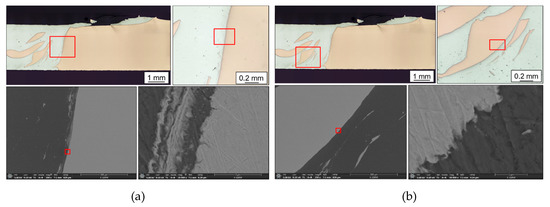
Figure 8.
BSE images of Al-Cu friction stir weld produced with parameter setting AlCu_1:(a) (Al-Cu interface), (b) Cu-particle.
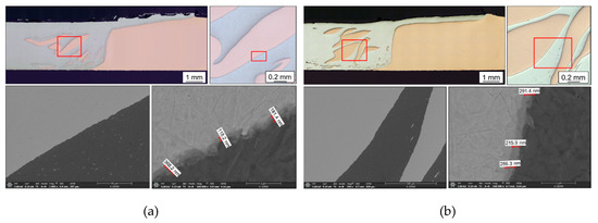
Figure 9.
(a) BSE images of Al-Cu friction stir welds produced with parameter setting AlCuopt_1 (Cu particle). (b) BSE images of Al-Cu friction stir weld produced with parameter setting AlCu_10 (Cu particle).
For further investigation of the tensile strength differences between parameter sets representing low or high heat input, Figure 10 shows hardness profiles on cross-sections of welds that were obtained using parameter settings AlCu_1 (n/v-ratio 0.4 1/mm) and AlCu_10 (n/v-ratio 0.86 1/mm). By means of hardness testing, process-related hardening or softening of the examined welds can be detected, so that any occurred strength-reducing microstructural features can be localized. Vickers hardness of the respective base material was found to be 37.7 HV 0.1 for the aluminum base material and 80.1 HV 0.1 for the copper base material. As shown for parameter setting AlCu_1 (n/v-ratio 0.4 1/mm) in Figure 10a, both in the stir zone (SZ) and on both sides in the thermo-mechanically affected zone (TMAZ), there is a significant increase in hardness compared to the respective base materials, with a hardness peak of 122 HV 0.1 in the SZ. This increase in hardness is to be explained by the effect of work hardening due to the cold welding parameters. On the other side, for the weld that was obtained using the parameter combination AlCu_10 (n/v-ratio 0.86 1/mm), the peak hardness values are significantly lower. Furthermore, a decrease in hardness can be seen in aluminum-sided in the SZ, and the plateau, on which the copper bulk material undergoes cold hardening, is clearly smaller. Therefore, the effect of recrystallization seems to dominate here.
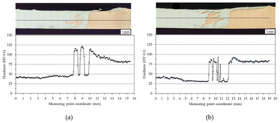
Figure 10.
Hardness profiles on cross-sections of Al-Cu joints: (a) Produced with parameter setting AlCu_1; (b) weld produced with parameter setting AlCu_10.
In order to understand how the mechanisms of work hardening and recrystallization affect a sample produced using the determined optimal parameter combination, the hardness profile shown in Figure 11 was analyzed. It can be seen that the aluminum material in the TMAZ as well as in the SZ is slightly hardened compared to the aluminum base material. A hardening of the copper particles introduced into the aluminum matrix cannot be detected, whereas the plateau, on which the copper bulk material undergoes cold hardening, is slightly wider than for AlCu_10. Taking into account parameter combination AlCuopt_1 achieving the highest tensile strength and the lowest electrical resistance, it is to be concluded that using these parameter settings, the ideal window for sufficient plasticization of the copper and for avoiding excessively high recrystallization in the SZ was determined.
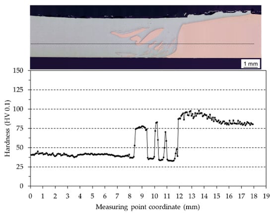
Figure 11.
Hardness profile on cross-section of Al-Cu joint produced with parameter setting AlCuopt_1.
At the end of this subsection, it is aimed to understand why scaling up of the optimal welding parameters while maintaining the n/v-ratio 0.57 1/mm could not be realized without losses in mechanical and electrical properties. An explanation for this is provided by the cross-sectional macrostructures in Figure 12. From the macrostructures, it becomes clear that the number and size of defects in the welded area increases with increasing traverse speed. While parameter combination AlCuopt_1 shows a homogeneous distribution of the copper particles without the occurrence of cavities or any other defects, parameter setting AlCuopt_4 leads to areas with insufficient bonding and strength-reducing tunnel defects in the root of the SZ. The parameter set AlCuopt_7 finally leads to a completely open seam root. From this, it can be concluded that although the tool rotation speed has been adjusted according to the feed speed, the material transport in the vertical direction has been reduced with increasing welding speeds. Thus, the plasticized material does not have enough time to be stirred behind the tool pin and sufficiently compacted by the tool shoulder. The shorter the time for plasticizing and stirring the materials is, the more the inertia of the joining partners promotes the formation of defects in the weld. Moreover, as shown by two publications from Lambiase et al. [25,26], the heat exchange mechanisms during the friction stir welding process need to be considered. The authors have found that the heat dissipation into the clamping device and the preheating of material in front of the welding tool vary depending on the traverse speed and the tool rotation speed. Actually, it is stated that the parameters “traverse speed” and “tool rotation speed” have a different influence on the heat exchange mechanisms, and thus, on the resulting temperature in the welding area. Consequently, it is to say that using the n/v-ratio as a heat index allows only a rough comparison of the heat input between different parameter settings in a limited range of process parameters.
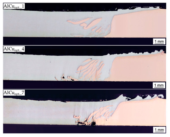
Figure 12.
Cross-sectional macrostructures of Al-Cu friction stir welds produced using parameter settings AlCuopt_1, AlCuopt_4, AlCuopt_7.
4. Conclusions
In this study, a parametric investigation on dissimilar friction stir butt welding of 3 mm thick aluminum EN AW-1050A and copper EN CW004A was performed, with the objective to maximize the welding speed at which joints with excellent mechanical and electrical performance can be produced. After designing a Taguchi experimental plan, welding tests were carried out and dependencies between input parameters and the target figure tensile strength and electrical resistance were determined.
- The target figure electrical resistance is more robust against parameter changes than the tensile strengths of the friction stir welds.
- It was found that the lowest offset in the considered parameter window (1.4 mm) led to the best mechanical and electrical properties. Cross-sectional macrostructures have proved that more intense material mixing when using low offsets improved the performance of the joint.
- The main effect plots did not show a steady effect of the factors traverse speed and tool rotation speed on the resultant tensile strength and electrical resistance. Instead, it was shown that the interaction of these two factors, which was expressed by the n/v-ratio, is crucial for the quality of the friction stir welds.
- It was recognized that cold welds, which were represented by a low n/v-ratio, tended to lead to better mechanical and electrical properties. This observation could be confirmed by the analysis of the Taguchi experimental plan.
- The effect of IMC on the resultant joint properties could be excluded. Instead, the varying tensile strength when welds were obtained with low or high heat input could be explained by the results of Vickers hardness testing.
- It was found that the optimal welding parameters for sufficient plasticization of the copper and for avoiding excessively high recrystallization in the SZ were traverse speed 700 mm/min, tool rotation speed 400 rpm, and offset 1.4. Friction stir welds that were manufactured using this parameter combination failed in the weaker aluminum base material during tensile testing and achieved an electrical resistance that was exactly between the resistances of the respective base materials. Scaling up the traverse speed and the tool rotation speed while maintaining the optimal n/v-ratio of 0.57 1/mm could not be realized without losses in mechanical and electrical joint properties. However, it could be shown by the investigations carried out that joints with a performance similar to those of the base materials used can be obtained using significantly higher welding speeds than reported in the relevant literature.
Author Contributions
Conceptualization, N.E., Y.H. and A.H.; methodology, N.E. and Y.H.; formal analysis, N.E., A.H., and D.L.; investigation, N.E. and Y.H.; writing—original draft preparation, N.E.; writing—review and editing, A.H., D.L., and S.B.; visualization, N.E. and Y.H.; supervision, A.H. and S.B.; project administration, A.H.
Funding
This research received no external funding.
Conflicts of Interest
The authors declare no conflict of interest.
Abbreviations
| FSW | Friction stir welding |
| Al | Aluminum |
| Cu | Copper |
| SEM | Scanning electron microscopy |
| BSE | Backscattered electrons |
| IMC | Intermetallic compounds |
References
- Bargel, H.-J.; Schulze, G. Werkstoffkunde; Springer: Berlin, Germany, 2016. [Google Scholar]
- Li, X.-W.; Zhang, D.-T.; Qiu, C.; Zhang, W. Microstructure and mechanical properties of dissimilar pure copper/1350 aluminum alloy butt joints by friction stir welding. Trans. Nonferrous Met. Soc. China 2012, 22, 1298–1306. [Google Scholar] [CrossRef]
- Braunovic, M.; Myshkin, N.K.; Konchits, V.V. Electrical Contacts. Fundamentals, Applications and Technology; Taylor & Francis Distributor: Boca Raton, FL, USA, 2007. [Google Scholar]
- Eslami, N.; Harms, A.; Deringer, J.; Fricke, A.; Böhm, S. Dissimilar friction stir butt welding of aluminum and copper with cross-section adjustment for current-carrying components. Metals 2018, 8, 661. [Google Scholar] [CrossRef]
- Carlone, P.; Astarita, A.; Palazzo, G.S.; Paradiso, V.; Squillace, A. Microstructural aspects in Al–Cu dissimilar joining by FSW. Int. J. Adv. Manuf. Technol. 2015, 79, 1109–1116. [Google Scholar] [CrossRef]
- Celik, S.; Cakir, R. Effect of friction stir welding parameters on the mechanical and microstructure properties of the Al-Cu butt joint. Metals 2016, 6, 133. [Google Scholar] [CrossRef]
- Akinlabi, E.T. Characterisation of Dissimilar Friction Stir Welds between 5754 Aluminium Alloy and C11000 Copper. Ph.D. Thesis, Nelson Mandela Metropolitan University, Port Elizabeth, South Africa, 2010. [Google Scholar]
- Al-Roubaiy, A.O.; Nabat, S.M.; Batako, A.D.L. Experimental and theoretical analysis of friction stir welding of Al–Cu joints. Int. J. Adv. Manuf. Technol. 2014, 71, 1631–1642. [Google Scholar] [CrossRef]
- Xue, P.; Ni, D.R.; Wang, D.; Xiao, B.L.; Ma, Z.Y. Effect of friction stir welding parameters on the microstructure and mechanical properties of the dissimilar Al–Cu joints. Mater. Sci. Eng. A 2011, 528, 4683–4689. [Google Scholar] [CrossRef]
- Xue, P.; Xiao, B.L.; Ni, D.R.; Ma, Z.Y. Enhanced mechanical properties of friction stir welded dissimilar Al–Cu joint by intermetallic compounds. Mater. Sci. Eng. A 2010, 527, 5723–5727. [Google Scholar] [CrossRef]
- Thomas, W.M.; Nicholas, E.D.; Needham, J.C.; Murch, M.G.; Templesmith, P.; Dawes, C.J. Improvements Relating to Friction Welding. PCT World Patent Application WO 93/10935, 10 June 1933. [Google Scholar]
- Mishra, R.S.; De, P.S.; Kumar, N. Friction Stir Welding and Processing. Science and Engineering; Springer International Publishing: Basel, Switzerland, 2014. [Google Scholar]
- Barekatain, H.; Kazeminezhad, M.; Kokabi, A.H. Microstructure and mechanical properties in dissimilar butt friction stir welding of severely plastic deformed aluminum AA 1050 and commercially pure copper sheets. J. Mater. Sci. Technol. 2014, 30, 826–834. [Google Scholar] [CrossRef]
- Galvão, I.; Oliveira, J.C.; Loureiro, A.; Rodrigues, D.M. Formation and distribution of brittle structures in friction stir welding of aluminium and copper: Influence of process parameters. Sci. Technol. Weld. Join. 2011, 16, 681–689. [Google Scholar] [CrossRef]
- Muthu, M.F.X.; Jayabalan, V. Tool travel speed effects on the microstructure of friction stir welded aluminum–copper joints. J. Mater. Process. Technol. 2015, 217, 105–113. [Google Scholar] [CrossRef]
- Ouyang, J.; Yarrapareddy, E.; Kovacevic, R. Microstructural evolution in the friction stir welded 6061 aluminum alloy (T6-temper condition) to copper. J. Mater. Process. Technol. 2006, 172, 110–122. [Google Scholar] [CrossRef]
- Zhang, Q.-Z.; Gong, W.-B.; Liu, W. Microstructure and mechanical properties of dissimilar Al-Cu joints by friction stir welding. Trans. Nonferrous Met. Soc. China 2015, 25, 1779–1786. [Google Scholar] [CrossRef]
- Deutsches Institut für Normung e. V. Aluminium und Aluminiumlegierungen—Chemische Zusammensetzung und Form von Halbzeug—Teil 3: Chemische Zusammensetzung und Erzeugnisformen; DIN EN 573-3; Beuth Verlag GmbH: Berlin, Germany, 2013. [Google Scholar]
- Deutsches Institut für Normung e. V. Kupfer und Kupferlegierungen—Platten, Bleche und Bänder aus Kupfer für die Anwendung in der Elektrotechnik; DIN EN 13599; Beuth Verlag GmbH: Berlin, Germany, 2014. [Google Scholar]
- Deutsches Institut für Normung e. V. Rührreibschweißen—Aluminium—Teil 5: Qualitäts- und Prüfungsanforderungen. DIN EN ISO 25239-5; Beuth Verlag GmbH: Berlin, Germany, 2012. [Google Scholar]
- Deutsches Institut für Normung e. V. Zerstörende Prüfung von Schweißverbindungen an Metallischen Werkstoffen—Querzugversuch; DIN EN ISO 4136:2012; Beuth Verlag GmbH: Berlin, Germany, 2013. [Google Scholar]
- Kleih, L.G. Theoretische und experimentelle Analyse des Bauteilverhaltens rührreibgeschweißter Überlappverbindungen. Ph.D. Thesis, Universitätsbibliothek der Universität Stuttgart, Stuttgart, Germany, 2014. [Google Scholar]
- Khodir, S.A.; Ahmed, M.M.Z.; Ahmed, E.; Mohamed, S.M.R.; Abdel-Aleem, H. Effect of intermetallic compound phases on the mechanical properties of the dissimilar Al/Cu friction stir welded joints. J. Mater. Eng. Perform. 2016, 25, 4637–4648. [Google Scholar] [CrossRef]
- Schmidt, P.A. Laserstrahlschweissen Elektrischer Kontakte von Lithium-Ionen-Batterien in Elektro- und Hybridfahrzeugen; Herbert Utz Verlag: Munich, Germany, 2015. [Google Scholar]
- Lambiase, F.; Paoletti, A.; Di Ilio, A. Forces and temperature variation during friction stir welding of aluminum alloy AA6082-T6. Int. J. Adv. Manuf. Technol. 2018, 99, 337–346. [Google Scholar] [CrossRef]
- Lambiase, F.; Paoletti, A.; Grossi, V.; Di Ilio, A. Analysis of loads, temperatures and welds morphology in FSW of polycarbonate. J. Mater. Process. Technol. 2018, 266, 639–650. [Google Scholar] [CrossRef]
© 2019 by the authors. Licensee MDPI, Basel, Switzerland. This article is an open access article distributed under the terms and conditions of the Creative Commons Attribution (CC BY) license (http://creativecommons.org/licenses/by/4.0/).