Abstract
The problem of chip breaking and evacuation is the key point of staggered teeth boring and trepanning association (BTA) drilling. The factors that influence chip breaking with staggered teeth BTA deep hole drilling are analyzed by using the chip bending deformation mechanism for chip formation and flow through the rake face and chip breaker. This study investigated the distribution and variation of chip deformation and breaking along drilling conditions, with respect to drilling radius, drilling process parameters, tool wear, and chip breaker geometric parameters. The results show that the tool-chip contact length is about 1.65 times the chip thickness in staggered teeth BTA drilling. The cutting radius of the teeth has a considerable influence on the chip thickness. Compared with the drilling speed, the feed has a greater impact on chip deformation and breaking, and the chip thickness and strain increase with increased feed. Increased drilling depth and tooth wear aggravates the friction state between the chip and the rake face, augments chip thickness and tool-chip contact length, and increases the chip’s strain increment. As the width of chip breaker decreases and the height increases, the chip strain increases and the breaking conditions are improved.
1. Introduction
Boring and trepanning association (BTA) deep hole drilling is a typical self-guiding machining method that is used for inner chip removal. The staggered teeth BTA drill adopts multiple teeth cutting, and two guide pads distributed on the outside of the drill ensure self-guiding in drilling, and improve the quality of the machined hole [1,2]. It is commonly applied in high-precision and high length-to-diameter ratio deep hole machining, e.g., in the fields of new energy, aerospace, and the military [3,4]. Due to the limitation of the chip removal channel area, the problem of chip breaking and evacuation is always a bottleneck in deep hole drilling, which is particularly difficult when drilling low-carbon alloy steel materials such as nuclear power tube-sheets, with strong toughness and plasticity [5,6,7,8]. In BTA deep hole drilling, if the size of the chip formation is not very regular and perfect, it might not guarantee smooth evacuation of the chip, which would lead to clogging of the chip removal channel, weakening of the cooling effect, increased drilling torque, and failure of the drill. Ultimately, the machining efficiency could be reduced, and expensive parts that are being processed could be scrapped [9,10].
Many researchers have studied chip deformation and breaking, in deep hole drilling. Gao et al. [11] explored the distribution of the chip deformation coefficient, and drilling force with the drilling process parameters for BTA deep hole drilling, and established a relationship model between the drilling force and the chip thickness deformation coefficient. Biermann et al. [12] used a gun drilling experiment performed on the hard material nickel-718, and acquired a variation of chip deformation with the approach angle of the cutting edge and drilling process parameters. Ke et al. [13] analyzed the varied laws of chip thickness with drilling depth in deep hole machining, using a twist drill. Rahman et al. [14] demonstrated the influence of the tool edge radius and cutting layer thickness on the chip morphology and quality of the machined hole. Sahu et al. [15] demonstrated that a chip breaker that is designed on the rake face of a twist drill could increase chip deformation and urge chip breaking, and established a drilling force model with the chip breaker. Lee et al. [16] designed three types of chip breakers as a turning tool, and their chip breaking effect was analyzed by the means of chip shape, breaking period, and breaking index. Wang et al. [17] studied chip formation and deformation in the deep hole machining process of a gun drill, and analyzed the wear mechanism of the cutting edge. As an important parameter of metal cutting, and tool-chip contact length affects not only cutting heat and tool wear, but also the curl deformation of the chip and the contact state between the chip and the chip breaker [18]. Fang [19,20] investigated the influence of tool–chip contact length on the cutting force and chip bending deformation by using the slip line theory of metal cutting. Maruda et al. [21] revealed the effects of cooling conditions on tool wear and chip deformation and breaking. The results showed that a decreased cutting zone temperature could effectively enhance chip breaking and reduce the length of chip formation. Biermann et al. [22] proposed a finite element model of staggered teeth BTA deep hole drilling by the topology optimization of the structure parameters of the drill, to increase the area of the chip removal channel and intensify the strength of the body. Tnay et al. [23] presented a numerical calculation fluid hydrodynamics model of single-lip deep hole gun drilling, revealing the effect of the dub-off angle on chip evacuation, and optimized the angle to increase chip removal efficiency.
To increase the bending deformation of chips and assist with chip breaking, the staggered teeth BTA drill is used with multiple teeth in misaligned dislocations, and the rake face of the tooth is designed with a chip breaker. However, owing to the different positions of the teeth and different drilling conditions, the laws of chip deformation and breaking are different. Meanwhile, there has not been complete theoretical guidance for designing chip breakers and matching the drilling process parameters up to now, and it can only rely on empirical values [3]. In this paper, the variation and distribution laws of chip deformation and breaking with the cutting radius, drilling parameters, tool wear, and chip breaker geometric parameters for staggered teeth BTA deep hole drilling are studied by experiments, which will provide a basis for optimizing the structural parameters of the drill and the selection of drilling process parameters.
2. Theoretical Analysis
The working principle of the BTA deep hole drill is shown in Figure 1. During drilling, the high cutting oil is injected from the cutting fluid supply apparatus into the top of the drill through the annular gap between the drilled hole wall and the outer cylindrical surface of the drill tube, which cools and lubricates the cutting zone and carries the formed chip by the teeth into the chip removal channel in the opposite direction. The chip is then is evacuated to the chip accumulation box. After chip separation, the cutting oil is repressurized and recycled by the oil pump to realize efficient, continuous deep hole machining. Therefore, whether a regular chip is formed or not is important in BTA deep hole drilling.
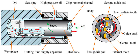
Figure 1.
Schematic of the boring and trepanning association (BTA) deep hole drilling system.
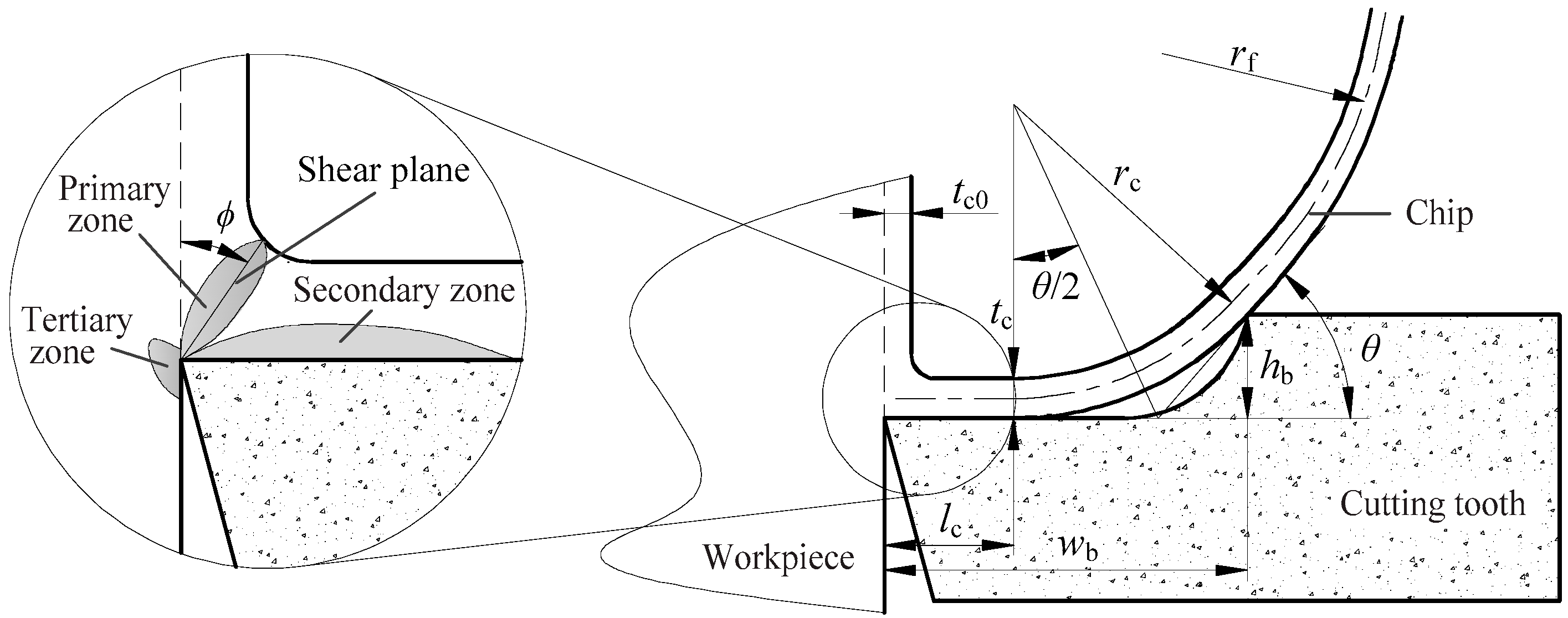
The staggered distribution of three teeth of the BTA drill creates a good splitting effect for forming chips to control the chip width, and the chip breakers on the rake face of each tooth enhance the chip bending deformation and fracture. By chip segmentation and with the aid of the chip breaker, the chip has a suitable profile size that can be successfully evacuated. In this paper, the deformation and breaking of the chip is mainly aimed at long chips from plastic material cutting. The process of chip formation and deformation is shown in Figure 2. The chip is formed after shearing and slipping of the cutting edge of the tooth and workpiece occurs in the primary deformation zone. The extrusion friction between the chip and the rake face takes place in the second deformation zone. The extrusion action of the rake face on the chip is like a distributed force applied on the side of a cantilever beam, resulting in a bending moment. Accordingly, there is a difference in the outflow velocity between the extruded surface (smooth surface) and the free surface (fold surface) of the formed chip, which brings about the chip’s bending deformation. Subsequently, the chip flowing out from the rake face is squeezed again by the chip breaker, and the bending deformation is further increased. Lastly, a circular arc with radius rc is formed at the endpoint of the tool–chip contact and the top of the chip breaker.
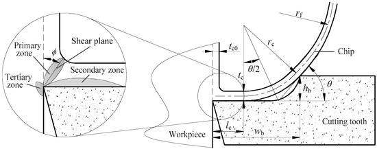
Figure 2.
Deformed model of the chip across the chip breaker.
The chip is in a free state after flowing out from the chip breaker. The chip, subjected to forced deformation, will produce elastic recovery, the curvature radius of the chip will enlarge, and the strain of the free surface of the chip also increases. When the strain of the chip is larger than the fracture strain of the material, the chip fracture will emerge. Based on the Nakayama chip deformation criterion, as the curl radius of the chip increases, the strain increment in the free surface of the chip can be given as follows:
where tc is the chip thickness, rf is the curvature radius at chip breaking, and K is the ratio of the chip radius, that is, K = rf/rc. In [24] it is shown that when 1.2 ≤ K ≤ 4, chip breaking of plastic material cutting will happen.
According to the model in Figure 2, the curvature radius rc of the chip through the chip breaker can be expressed as:
where wb is the width of the chip breaker, hb is the height of the chip breaker, lc is the tool-chip contact length, and θ is the chip curl-up angle.
Substituting Equation (2) into Equation (1) leads to:
On the basis of Equation (4), the chip thickness, tool-chip contact length, and chip breaker geometric parameters will directly affect the chip strain. Furthermore, the chip thickness is related not only to the cutting angles of the teeth and the physical properties of workpiece material, but also to drilling conditions (including the cutting radius, drilling process parameters, and tool wear) [17,25]. Only when the distribution and variation rules of the chip thickness and tool-chip contact length are clarified, can the appropriate dimension parameters of chip breakers be selected for each tooth to match the drilling process parameters and the bending deformation strain of chip be controlled, thus ensuring a good chip-breaking effect.
3. Experimental Conditions and Methods
The experimental platform and staggered teeth BTA drill are shown in Figure 3. The drill tube length was 1500 mm, the maximum drilling depth was 1000 mm, the drilling speed range was 0–2000 r/min, the cutting oil dynamic viscosity was 1.33 × 10⁻² Pa·s, the maximum supply pressure was 6 MPa, and flow rate was 90 L/min. The material of the workpiece was high-strength low-carbon alloy SA508-3 steel, selected for the nuclear tube plate. The workpiece size was 800 mm long, 500 mm wide, and 200 mm in height, and its physical parameters are shown in Table 1 [25].
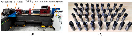
Figure 3.
(a) Experimental platform and (b) staggered teeth BTA drill.

Table 1.
Physical characteristic parameters of SA508-3 steel.
To explore the effect of the chip breaker geometric parameters on chip strain, the widths and heights of three teeth chip breakers (Φ17.75 mm) of a staggered teeth BTA drill, which had a TiAlN coating, were ground to the dimensions shown in Table 2. By a single factor experiment under a feed of 0.04–0.12 mm/r, and a rotating speed of 800–1600 r/min, the drilling depth for each experiment was kept constant at 50 mm, to reduce the effect of tool wear, and the experiment was repeated three times. From the collected chips, 10 pieces were randomly selected from each tooth, and after washing the chips with anhydrous alcohol, a Keyence VHX-5000 electron microscope (KEYENCE Co., Itasca, IL, USA) equipped with image processing software was used to observe and measure the chips, and to obtain the variations of chip thickness with the cutting radius of the teeth, drilling process parameters, and tool wear. The tool-chip contact length was obtained by measuring the tool-chip contact area of three new tools after drilling a hole and averaging.
Table 2.
Chip breaker geometric parameters of the staggered teeth BTA drill.
4. Results and Discussion
4.1. Chip Thickness
Using a No. 5 drill under the drilling conditions of speed 1200 r/min and feed 0.1 mm/r, cross-sections of chips from the three teeth were viewed under the microscope, as shown in Figure 4. Since the three teeth had different positions and different cutting radius, the shapes of their chips were quite different. The chip thickness along the cutting radius was measured by electron microscopy, and the results are shown in Figure 5. Chip thickness tc increases with increased cutting radius r of the teeth, and the curve of tc − r is approximately a straight line, and its slope decreases successively from the central to the intermediate to the external tooth. The maximum chip thickness is located at the maximum cutting radius edge of the tooth, and it decreases from the central to the intermediate to the external tooth. The maximum chip thickness of the external tooth is 0.215 mm, and its ratio is 1.53:1.17:1, representing the central, intermediate, and external teeth, respectively.
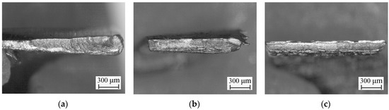
Figure 4.
Cross-sections along the flowing out of the chip: (a) central tooth, (b) intermediate tooth, (c) external tooth.
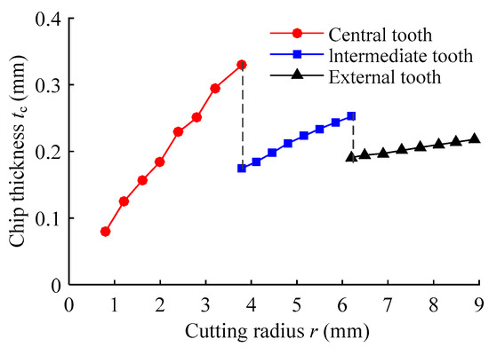
Figure 5.
Distribution of chip thickness along cutting radius.
In BTA deep hole drilling, with increased cutting radius, the material removal rate, chip outflow velocity, and curvature radius of the chip increase, but there is the same curl pitch of the chip in the flowing process [13,26], as shown in Figure 6. When the high-temperature chip flows out, the chip at the minimum cutting radius edge will be stretched, resulting in reduced chip thickness. Therefore, the chip thickness at each tooth increases with increased cutting radius.
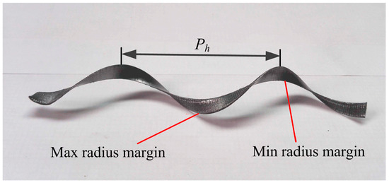
Figure 6.
Profile of the continuous chip from external tooth cutting.
Assuming that the same volume for the chip formed and for the workpiece material removed, the chip thickness flowing out on the cutting radius r is as follows:
where V(r) is volume of workpiece material removed per unit of time on the cutting radius r, v(r) is the chip flowing velocity on the cutting radius r, ω is the angular velocity of the drill rotation, and tc0 is the cutting layer thickness.
Because the chip during BTA deep hole drilling has the same curl pitch, v(r) can be expressed as:
where Ph is the pitch of the chip flow, R is the maximum cutting radius of the tooth, vR is the chip flowing velocity on the maximum cutting radius, vR = wRtC0/tCR, and tcR is the chip thickness on the maximum cutting radius.
By substituting Equations (6) and (7) into Equation (5), the chip thickness along the cutting radius can be obtained as follows:
It can be seen from Equation (8) that the increase rate of the chip thickness of the central teeth is the largest, because of the large change of the cutting radius. With the increased cutting radius, there is a small change in the cutting radius of the intermediate and external teeth, and a reduction in the increase rate of chip thickness.
The chip morphology of the maximum cutting radius edge of the three teeth is shown in Figure 7. The metal cutting process is a discontinuous shear slipping in the shear zone, and the formed chip must pass through three stages of sliding, stay-stacking, and sliding in the second deformation zone [27,28]. The cutting radius of the central tooth is small and the linear velocity is low, and the extrusion action is greater than that of the shearing action, and the width of the shear zone is increased, which leads to increased normal pressure between the chip and the rake face in the second deformation zone [29]. Therefore, the force that is needed to overcome the static friction between the chip and the rake face, the stay-stacking time, and the chip thickness all increase. Moreover, the rake angle of the central tooth is smaller than that of the intermediate and external teeth. As the cutting radius of the intermediate and external teeth increases, the cutting speed increases, the cutting condition improves, the strain rate in the shear zone increases, more heat is generated, the temperature is higher in the cutting zone, and the plastic flowability of the material is enhanced. The extrusion and friction between the chip and the rake face become smaller, the chip is easier to form and flow out, the stacking effect of the chip is weakened, and the chip thickness is reduced. Hence, the chip thicknesses of the central, intermediate, and external teeth are decreased in order.
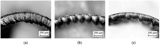
Figure 7.
Chip morphology at maximum cutting radius edge: (a) central tooth, (b) intermediate tooth, (c) external tooth.
Because the chip thickness and curl radius of the chip are larger at the maximum cutting radius edge of the teeth, the chip first contacts the chip breaker, resulting in extrusion deformation after the chip flows from the rake face. Therefore, the chip thickness at the maximum cutting radius of each tooth is regarded as the object of research. Under different feeds at a speed of 1200 r/min, and different speeds at a feed of 0.1 mm/r, the influence of drilling parameters on the chip thickness of the teeth is studied. Chip thicknesses under different drilling process parameters are shown in Figure 8. The variation trend of the chip thickness of the three teeth is basically the same, with the central tooth being larger than the intermediate tooth, which is larger than the external tooth. With increased feed, the chip thickness increases, and it decreases with increased speed, but the effect of speed is less, since the cutting layer thickness and the deformation coefficient of the chip increase with increased feed [25]. Consequently, with increased feed rate, the chip thickness increases apparently. Furthermore, with increased speed, the linear velocity of the cutting increases, the increment of heat produced from the primary and second deformation zones increases, the temperature of the cutting zone rises, chip plasticity improves, and the lubrication conditions between the chip and the rake face can be elevated. Therefore, the stacking effect of the chip on the rake face is reduced, and the chip thickness is decreased.
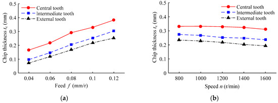
Figure 8.
The effect of drilling process parameters on chip thickness: (a) under different drilling feeds at a speed of 1200 r/min; (b) under different drilling speeds at a feed of 0.1 mm/r.
Compared with the external and intermediate teeth in the staggered teeth BTA drill, the central tooth has a low material removal rate and slow wear. Therefore, when exploring the influence of drill wear on chip thickness, only the external and intermediate teeth are considered. Flank wear land width and chip thickness are measured by electron microscope after drilling each hole (depth 800 mm) with a No. 5 drill. To ensure the dimensional accuracy of the machined hole, the blunt standard of the tooth is set as the flank wear land width VB = 0.25 mm [30]. The chip thickness and the flank wear land width with regard to the variation of drilling depth are shown in Figure 9. After drilling to a depth of 13.6 m, the external tooth reaches the blunt standard. With increased drilling depth, the flank wear land width increases, the wear land width of the external tooth is larger than that of the intermediate tooth, and the wear of the external tooth is accelerated after drilling to 12 m. Additionally, during wearing and blunting, the chip thickness of the intermediate and external teeth increase by 9.75% and 18.34%, respectively. When the external tooth reaches the sharp wear stage, its chip thickness growth rate slows down.
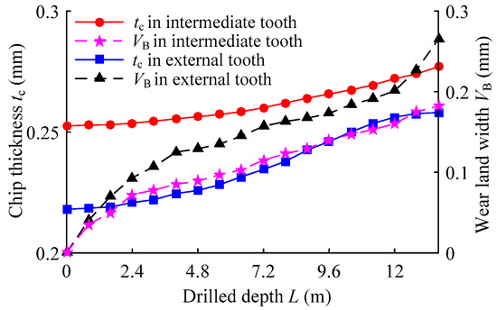
Figure 9.
Effect of the drilling depth on tool wear and chip thickness.
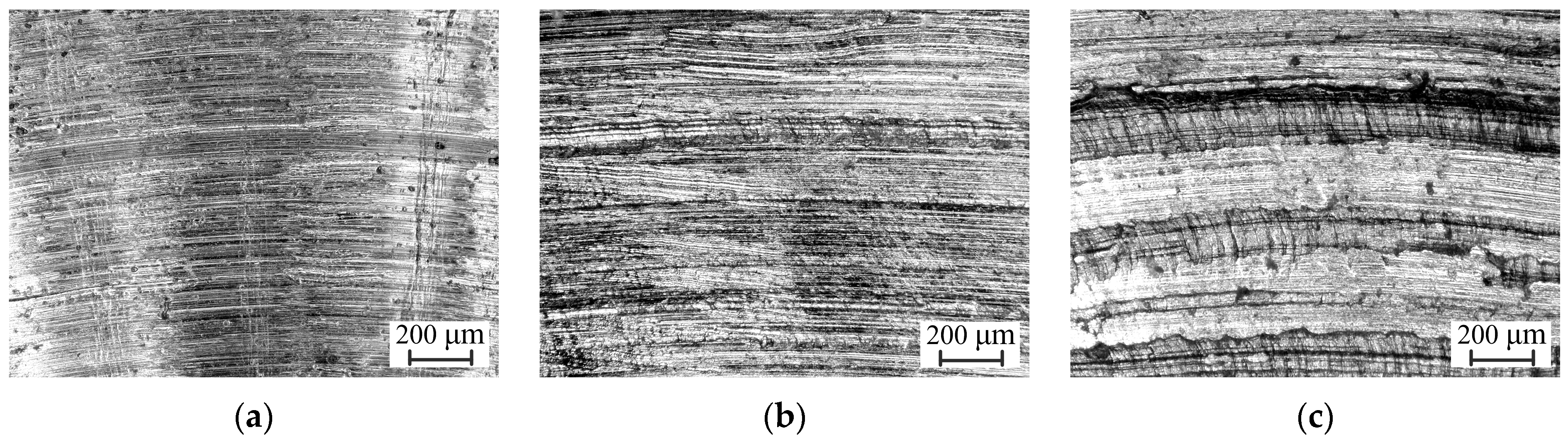
The morphology of the extruded surface of the external tooth chip with drilling depths of 0.8 m, 7.2 m, and 13.6 m is shown in Figure 10. With increased drilling depth, the teeth mutually scratch the chip formed in the second deformation zone and the workpiece in the tertiary deformation zone, forming a crater on the rake face and a flank wear land. With the aggravation of wear and the deterioration of the lubrication conditions of the chip and the rake face, the roughness of the chip’s extruded surface is increased, and grooves appear. The friction between the chip and the rake face increases, the resistance of the chip flow increases, and the chip thickness increases [31,32]. In addition, after the bluntness of the teeth and the abrading of tool coating, the cutting force, and the heat generated in the cutting zone increase. Due to the thermal softening effect of the material, the plastic flow is enhanced [17], and the growth of the chip thickness tends to be gentle.

Figure 10.
Morphology of the chip-extruded surface of the external tooth: (a) a drilled depth of 0.8 m, (b) a drilled depth of 7.2 m, (c) a drilled depth of 13.6 m.
4.2. Tool-Chip Contact Length
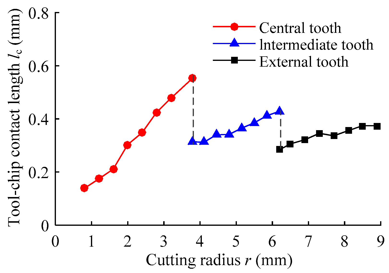
The extrusion friction contact between the formed chip and the rake face of the tooth leaves wear tracks in the second deformation zone. The wear area of the rake face after drilling a hole using the new drill is regarded as the tool-chip contact area. The drilling depth should not be too small, so that the wear tracks are clear, and it is easy to accurately identify the wear area, and to prevent it from being affected by tool wear. Figure 11 shows the tool-chip contact area of each tooth of the staggered teeth BTA deep hole drill, using a No. 5 drill at a feed of 0.1 mm/r, and a speed of 1200 r/min. The tool-chip contact areas were equally measured perpendicular to the cutting edge by an electron microscope, and the obtained distribution of the tool-chip contact length with the cutting radius is shown in Figure 12. It can be seen that this distribution is basically consistent with that of the chip thickness. With an increased cutting radius, the tool-chip contact length increases. The maximum tool-chip contact length was located at the maximum cutting radius edge of the tooth, and the ratio of the central to the intermediate to the external tooth was 1.48:1.15:1. The curvature radius of the chip and tool-chip contact lengths increased with an increased drilling radius on the same tooth. Moreover, the chip thickness of the central tooth was larger than the intermediate tooth, which was larger than the external tooth, and a thin chip had less resistance to bending deformation after contact with the rake face, from which it could easily be separated. Therefore, the tool-chip contact length of the central tooth was the largest at the maximum cutting radius edge.
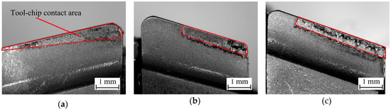
Figure 11.
Tool–chip contact area of each tooth for staggered teeth BTA drill: (a) the central tooth, (b) the intermediate tooth, (c) the external tooth.
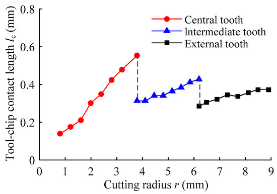
Figure 12.
Distribution of the tool–chip contact length along cutting radius.
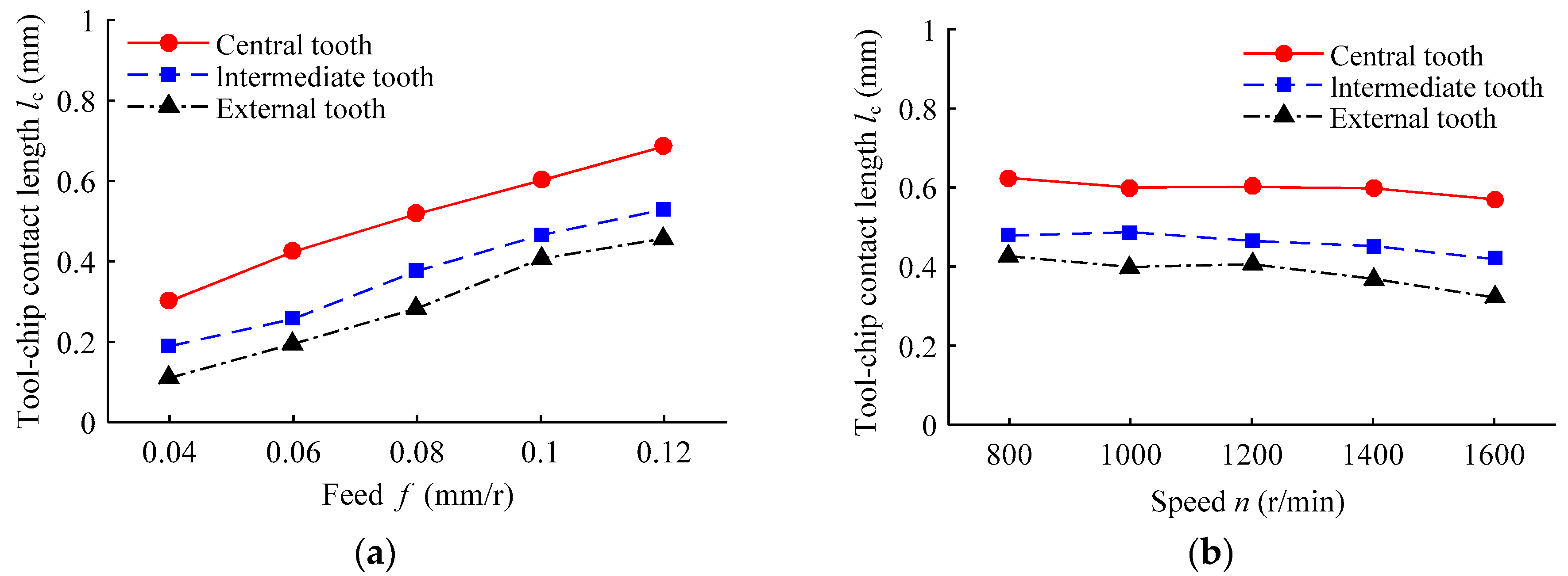
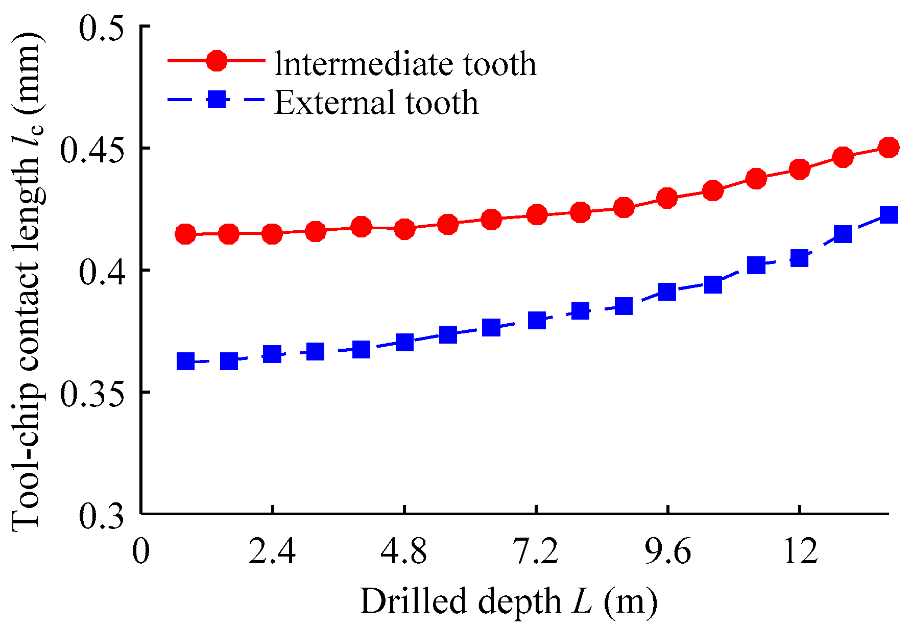
The tool-chip contact length under different drilling process parameters is shown in Figure 13. The variations of the tool-chip contact lengths of the three teeth with drilling process parameters was the same. With increased feed, the tool-chip contact lengths increased, and it decreased with increased speed. The tool-chip contact lengths with drilling depth are shown in Figure 14. As the drilling depth increased, the contact length increased, and the intermediate and external teeth increased by 8.54% and 16.62%, respectively. Since the chip contact area was divided into a sticking zone that was close to the cutting edge, and a sliding zone that was close to the separated side of the chip and the rake face, the positive pressure on the sliding zone was small, so that the increase of the tool-chip contact length was not very obvious, compared to the flank wear land width [33]. Meanwhile, because the depth of the crater on the rake face is small, we can ignore the error with actual contact length. In reference [19] according to the slip-line model of metal cutting, the tool-chip contact length is found to be twice the chip thickness. However, BTA deep hole drilling is different from normal metal cutting: the staggered teeth BTA drill is always in the high-pressure cutting fluid, so that the temperature and lubrication conditions in the cutting zone are improved, and the tool–chip contact length is reduced. Based on the experimental results at different drilling conditions, the tool-chip contact length of staggered teeth BTA deep hole drilling is approximately 1.65 times the chip thickness, that is, lc = 1.65 tc.
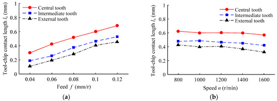
Figure 13.
Effect of the drilling process parameters on the tool-chip contact length: (a) under different drilling feeds at a speed of 1200 r/min; (b) under different drilling speeds at a feed of 0.1 mm/r.

Figure 14.
Effect of the drilling depth on the tool-chip contact length.
4.3. Chip-Strain Increment
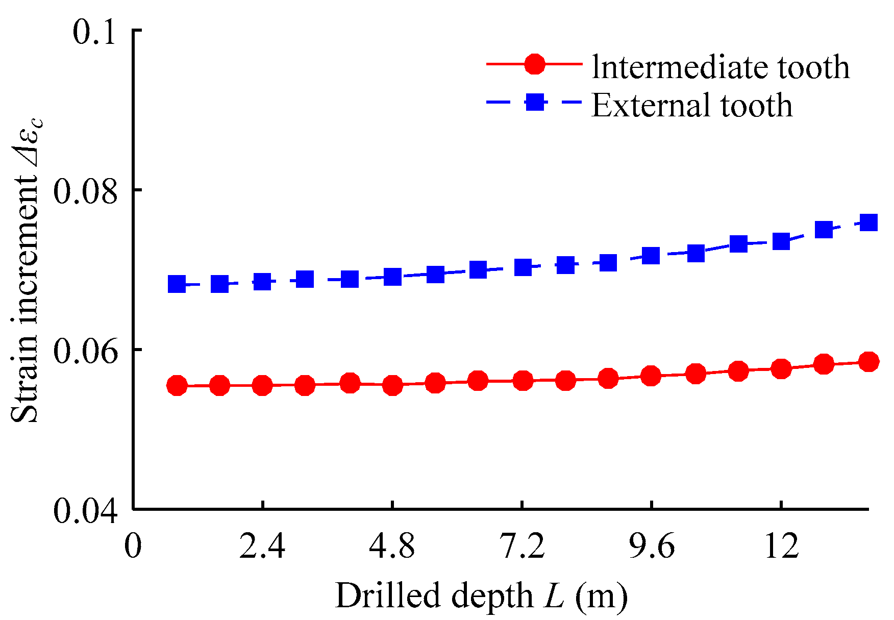
Chip thickness and tool-chip contact length under different drilling conditions are substituted into Equation (5) to obtain the strain increment of the chip, as shown in Figure 15. Considering the toughness and plasticity of the SA508-3 material, the chip radius change ratio is K = 3.8 [25]. The chip strain increment of the central tooth is larger than that of the external and intermediate teeth. With an increased drilling feed, the chip strain increment and its growth rate increases. The chip breaking of the central tooth occurs at a feed of 0.06 mm/r, and of the external and intermediate teeth at a feed of 0.08 mm/r, and the chip breaking of the central tooth is worse. As the speed increases, the chip strain increment of the central tooth is almost unchanged, while that of the external and intermediate teeth decreases. The variation of the chip-strain increment with drill wear is shown in Figure 16. With the increased drilling depth, the wear of the teeth, the chip thickness, and the chip strain increment increase. As the feed increases, the chip thickness and tool-chip contact length, the bending deformation energy of the rake face and chip breaker applied to the chip, and the chip strain all increase, and chip breaking becomes easier. When the speed increases, the cutting layer thickness is constant, the chip thickness decreases, and the chip temperature, elongation of chip material, and the breaking strain of the chip all increase, which has the disadvantage of the chip breaking.

Figure 15.
Effect of the drilling process parameters on the chip strain increment: (a) under different drilling feeds at a speed of 1200 r/min; (b) under different drilling speeds at a feed of 0.1 mm/r.
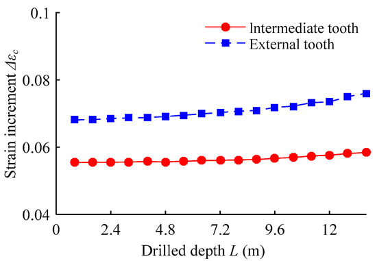
Figure 16.
Effect of the drilling depth on the chip strain increment.
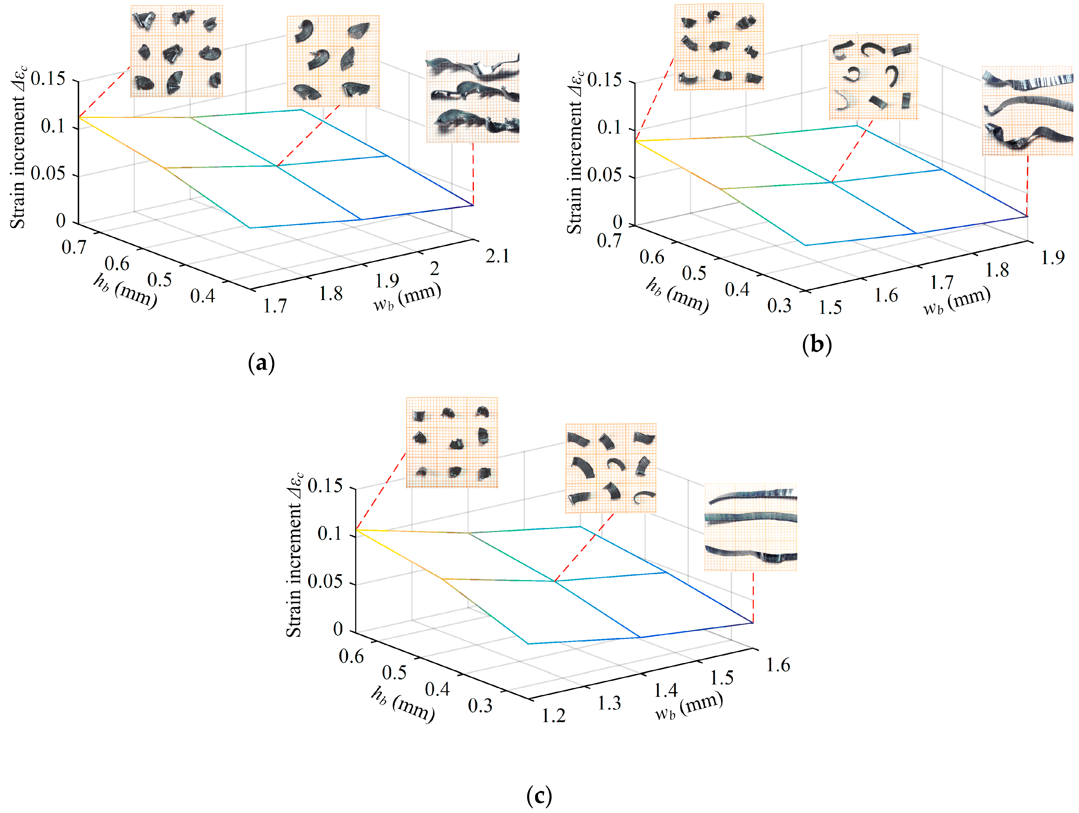
Staggered teeth BTA drills with different geometric parameters of chip breaker at a feed of 0.1 mm/r, a speed of 1200 r/min, chip strain increment, and corresponding teeth chip are shown in Figure 17. The geometric parameters of the chip breaker will directly affect the chip curl-up angle and the curvature radius, affecting the chip strain. Since the chip thickness of the central tooth is large, and it has a large variation gradient, the chip strain increment is greatly influenced by the size of the chip breaker. As the width of the chip breaker increases and the height decreases, the chip strain increment decreases, and the chip breaking conditions deteriorate; conversely, as the width of the chip breaker decreases and the height increases, the chip strain increment increases and the chip breaking conditions are lifted. However, if the chip breaker width is too small and the height is too large, the chip is subjected to excessive extrusion deformation, resulting in severely uneven thickness, which will lead to large fluctuations in the drilling force, poor drilling stability, and easy tooth breakage.

Figure 17.
The tool-chip contact area of each tooth for staggered teeth BTA drill: (a) the central tooth, (b) the intermediate tooth, (c) the external tooth.
5. Conclusions
The factors that influence the chip breaking of staggered teeth BTA deep hole drilling were analyzed by using the chip bending deformation mechanism. The distribution and variation laws of chip deformation and breaking with the drilling radius, drilling process parameters, tool wear, and chip breaker dimension parameters were investigated. From the above study, the following conclusions are drawn.
The cutting radius of the teeth has a great influence on the chip thickness. The chip thickness increases with increased cutting radius, and its growth rate decreases in the order of central, intermediate, and external tooth. The maximum chip thickness of each tooth is located at the maximum cutting radius edge, and the maximum chip thickness ratio of the central, intermediate, and external teeth is 1.53:1.17:1.
The variation of the chip thickness of the three teeth is similar under different drilling process parameters. As the feed increases to 0.04–0.12 mm/r, the chip thickness increases. With the drilling speed increased to a rotating speed of 800–1600 r/min, the chip thickness decreases, and the drilling speed has less influence than the feed. As the drilling depth and tool wear increase, the chip thickness increases.
The tool-chip contact length with the drilling condition is basically the same as the chip thickness. In the staggered teeth BTA deep hole drilling process, the tool-chip contact length is about 1.65 times the chip thickness. The chip strain increment of the three teeth decreases sequentially from the central to the external to the intermediate tooth. The chip strain increases with the increase of the drilling feed, and the width of the chip breaker decreases, and the height increases, which can improve chip breaking conditions.
Author Contributions
Conceptualization, X.-B.L. and J.-M.Z.; Data curation, X.-B.L.; Funding acquisition, J.-M.Z. and L.-F.K.; Investigation, X.-B.L. and B.G.; Methodology, X.-B.L. and L.-F.K.; Project administration, J.-M.Z.; Writing—original draft, X.-B.L. and W.-C.S.; Writing—review & editing, J.-M.Z. and Y.L.
Funding
This research was funded by National Science and Technology Major Project of China (Grant No. 2013ZX04009011), National Natural Science Foundation of China (Grant No. 51475367), Key Laboratory Project of Shaanxi Education Department (Grant No. 17JS093), and Natural Science Foundation of Department of Education of Shaanxi Province (Grant No. 2018JM5113).
Acknowledgments
Thank the National Science and Technology Major Project of China, the National Natural Science Foundation of China, the Key Laboratory Project of Shaanxi Education Department and Natural Science Foundation of Department of Education of Shaanxi Province.
Conflicts of Interest
The authors declare no conflict of interest.
References
- Zhang, H.; Shen, X.Q.; Bo, A.; Li, Y.M.; Zhan, H.F.; Gu, Y.T. A multiscale evaluation of the surface integrity in boring trepanning association deep hole drilling. Int. J. Mach. Tools Manuf. 2017, 123, 48–56. [Google Scholar] [CrossRef]
- Matsuzaki, K.; Ryu, T.; Sueoka, A.; Tsukamoto, K. Theoretical and experimental study on rifling mark generating phenomena in BTA deep hole drilling process (generating mechanism and countermeasure). Int. J. Mach. Tools Manuf. 2015, 88, 194–205. [Google Scholar] [CrossRef]
- Kong, L.F.; Chin, J.H.; Li, Y.; Lu, Y.J.; Li, P.Y. Targeted suppression of vibration in deep hole drilling using magneto-rheological fluid damper. J. Mater. Process. Technol. 2014, 55, 2617–2626. [Google Scholar] [CrossRef]
- Biermann, D.; Bleicher, F.; Heisel, U.; Klocke, F.; Möhring, H.-C.; Shih, A. Deep hole drilling. CIRP Ann. Manuf. Technol. 2018, 67, 673–694. [Google Scholar] [CrossRef]
- Biermann, D.; Kirschner, M.; Eberhardt, D. A novel method for chip formation analyses in deep hole drilling with small diameters. Prod. Eng. 2014, 8, 491–497. [Google Scholar] [CrossRef]
- Astakhov, V.P.; Galitsky, V.V.; Osman, M.O.M. A novel approach to the design of self-piloting drills with external chip removal, part 1: Geometry of the cutting tip and grinding process. J. Manuf. Sci. Eng. 1995, 117, 453–463. [Google Scholar] [CrossRef]
- Woon, K.S.; Tnay, G.L.; Rahman, M.; Wan, S.; Yeo, S.H. A computational fluid dynamics (CFD) model for effective coolant application in deep hole gundrilling. Int. J. Mach. Tools Manuf. 2017, 113, 10–18. [Google Scholar] [CrossRef]
- Chaudhari, A.; Malarvizhi, S.; Woon, K.S.; Kumar, A.S.; Rahman, M. The effects of pilot hole geometry on tool-work engagement efficacy in deep hole drilling. J. Manuf. Process. 2015, 19, 135–141. [Google Scholar] [CrossRef]
- Woon, K.S.; Tnay, G.L.; Rahman, M. Improving coolant effectiveness through drill design optimization in gundrilling. Mater. Sci. Eng. 2018, 370, 1–9. [Google Scholar] [CrossRef]
- Aramcharoen, A. Influence of cryogenic cooling on tool wear and chip formation in turning of titanium alloy. Procedia CIRP 2016, 46, 83–86. [Google Scholar] [CrossRef]
- Gao, C.H.; Cheng, K.; Kirkwood, D. The investigation on the machining process of BTA deep hole drilling. J. Mater. Process. Technol. 2001, 107, 222–227. [Google Scholar] [CrossRef]
- Biermann, D.; Kirschner, M. Experimental investigations on single-lip deep hole drilling of superalloy Inconel 718 with small diameters. J. Manuf. Process. 2015, 20, 332–339. [Google Scholar] [CrossRef]
- Ke, F.; Ni, J.; Stephenson, D.A. Chip thickening in deep-hole drilling. Int. J. Mach. Tools Manuf. 2006, 46, 1500–1507. [Google Scholar] [CrossRef]
- Rahman, M.A.; Woon, K.S.; Venkatesh, V.C.; Rahman, M. Modelling of the combined microstructural and cutting edge effects in ultra precision machining. CIRP Ann. Manuf. Technol. 2018, 67, 129–132. [Google Scholar] [CrossRef]
- Sahu, S.K.; DeVor, R.E.; Kapoor, S.G. Modeling of forces for drills with chip-breaking grooves. J. Manuf. Sci. Eng. 2004, 126, 555–564. [Google Scholar] [CrossRef]
- Lee, Y.M.; Yang, S.H.; Chang, S.I. Assessment of chip-breaking characteristics using new chip-breaking index. J. Mater. Process. Technol. 2006, 173, 166–171. [Google Scholar] [CrossRef]
- Wang, Y.G.; Yan, X.P.; Li, B.; Tu, G.C. The study on the chip formation and wear behavior for drilling forged steel S48CS1V with TiAlN-coated gun drill. Int. J. Refractory Metals Hard Mater. 2012, 30, 200–207. [Google Scholar] [CrossRef]
- Toropov, A.; Ko, K.L. Prediction of tool-chip contact length using a new slip-line solution for orthogonal cutting. Int. J. Mach. Tools Manuf. 2003, 43, 1209–1215. [Google Scholar] [CrossRef]
- Fang, N. Machining with tool-chip contact on the tool secondary rake face—Part I: A new slip-line model. Int. J. Mech. Sci. 2002, 44, 2337–2354. [Google Scholar] [CrossRef]
- Fang, N. Machining with tool-chip contact on the tool secondary rake face—Part II: Analysis and discussion. Int. J. Mech. Sci. 2002, 44, 2355–2368. [Google Scholar] [CrossRef]
- Maruda, R.W.; Krolczyk, G.M.; Nieslony, P.; Wojciechowski, S.; Michalski, M.; Legutko, S. The influence of the cooling conditions on the cutting tool wear and the chip formation mechanism. J. Manuf. Process. 2016, 24, 107–115. [Google Scholar] [CrossRef]
- Biermann, D.; Kersting, M.; Kessler, N. Process adapted structure optimization of deep hole drilling tools. CIRP Ann. Manuf. Technol. 2009, 58, 89–92. [Google Scholar] [CrossRef]
- Tnay, G.L.; Wan, S.; Woon, K.S.; Yeo, S.H. The effects of dub-off angle on chip evacuation in single-lip deep hole gun drilling. Int. J. Mach. Tools Manuf. 2016, 108, 66–73. [Google Scholar] [CrossRef]
- Zhang, Y.Z.; Peklenik, J. Chip curl, chip breaking and chip control of the difficult-to-cut materials. CIRP Ann. Manuf. Technol. 1980, 29, 79–83. [Google Scholar] [CrossRef]
- Thil, J.; Haddag, B.; Nouari, M.; Barlier, C.; Papillon, L. Experimental and analytical analyses of the cutting process in the deep hole drilling with BTA (Boring Trepanning Association) system. Mech. Ind. 2014, 14, 413–429. [Google Scholar] [CrossRef]
- Buchkremer, S.; Klocke, F.; Lung, D. Finite-element-analysis of the relationship between chip geometry and stress triaxiality distribution in the chip breakage location of metal cutting operations. Simul. Model. Pract. Theory 2015, 55, 10–26. [Google Scholar] [CrossRef]
- Pan, H.; Liu, J.; Choi, Y.; Xu, C.; Bai, Y.; Atkins, T. Zones of material separation in simulations of cutting. Int. J. Mech. Sci. 2016, 115–116, 262–279. [Google Scholar] [CrossRef]
- Melkote, S.N.; Liu, R.; Fernandez-Zelaia, P.; Marusich, T. A physically based constitutive model for simulation of segmented chip formation in orthogonal cutting of commercially pure titanium. CIRP Ann. Manuf. Technol. 2015, 64, 65–68. [Google Scholar] [CrossRef]
- Buchkremer, S.; Klocke, F. Compilation of a thermodynamics based process signature for the formation of residual surface stresses in metal cutting. Wear 2017, 376–377, 1156–1163. [Google Scholar] [CrossRef]
- Rao, P.K.R.; Shunmugam, M.S. Wear studies in boring trepanning association drilling. Wear 1988, 124, 33–43. [Google Scholar] [CrossRef]
- Kirschner, M.; Michel, S.; Berger, S.; Biermann, D.; Debus, J.; Braukmann, D.; Bayer, M. In situ chip formation analyses in micro single-lip and twist deep hole drilling. Int. J. Adv. Manuf. Technol. 2018, 95, 2315–2324. [Google Scholar] [CrossRef]
- Dargusch, M.S.; Sun, S.J.; Kim, J.W.; Li, T.; Trimby, P.; Cairney, J. Effect of tool wear evolution on chip formation during dry machining of Ti-6Al-4V alloy. Int. J. Mach. Tools Manuf. 2018, 126, 13–17. [Google Scholar] [CrossRef]
- Bai, W.; Sun, R.L.; Roy, A.; Silberschmidt, V.V. Improved analytical prediction of chip formation in orthogonal cutting of titanium alloy Ti6Al4V. Int. J. Mech. Sci. 2017, 133, 357–367. [Google Scholar] [CrossRef]


© 2019 by the authors. Licensee MDPI, Basel, Switzerland. This article is an open access article distributed under the terms and conditions of the Creative Commons Attribution (CC BY) license (http://creativecommons.org/licenses/by/4.0/).