Stainless steels constitute a big group of different materials with a large variety of composition, and thermophysical and mechanical properties. Considering the focus of the present work on the home-appliance industry, the welding of an austenitic with a ferritic stainless steel is studied. The AISI 301 steel has been selected as the austenitic steel, coming from a cold-rolled coil with surface finish 2R (Bright Annealing (B.A.)) obtained from ACERINOX
® (Madrid, Spain). The main alloy elements of the AISI 301 steel were chromium (~17 wt. % Cr) and nickel (~7 wt. % Ni), while its carbon content was limited to 0.08 wt. % C. The AISI 301 steel shows high tenacity, high corrosion resistance and, from the point of view of esthetical requirements, good surface brightness. The AISI 430Ti, coming from a cold-rolled coil with surface finish 2R (BA) obtained from ACERINOX
® was chosen as the ferritic steel, given its wide use. The AISI 430Ti steel has medium resistance to corrosive atmospheres and sulphurous gases. The addition of titanium as alloy elements avoids the precipitation or chromium carbides in the grain edges associated with the basic AISI 430 steel [
19].
Table 1 contains the composition of the steels used in the work considering the grade, heat treatments, and the manufacturer.
The thickness of the plates for all the welding experiments was 0.4 mm as was the laser beam diameter. This value is considered typical for both magnitudes, thickness and diameter. In addition, the beam diameter is considered to be strongly related with the depth and size of the welding pool. If the thickness of the plate is shorter than the beam diameter, the material melts before having the possibility of reaching the keyhole regime; however, if the thickness is larger than the beam diameter, it is impossible to make the welding pool traverse the material maintaining the conduction regime. Consequently, the coincidence between the beam diameter and the thickness of the plate permits the different welding modes to be studied for the same configuration of the process.
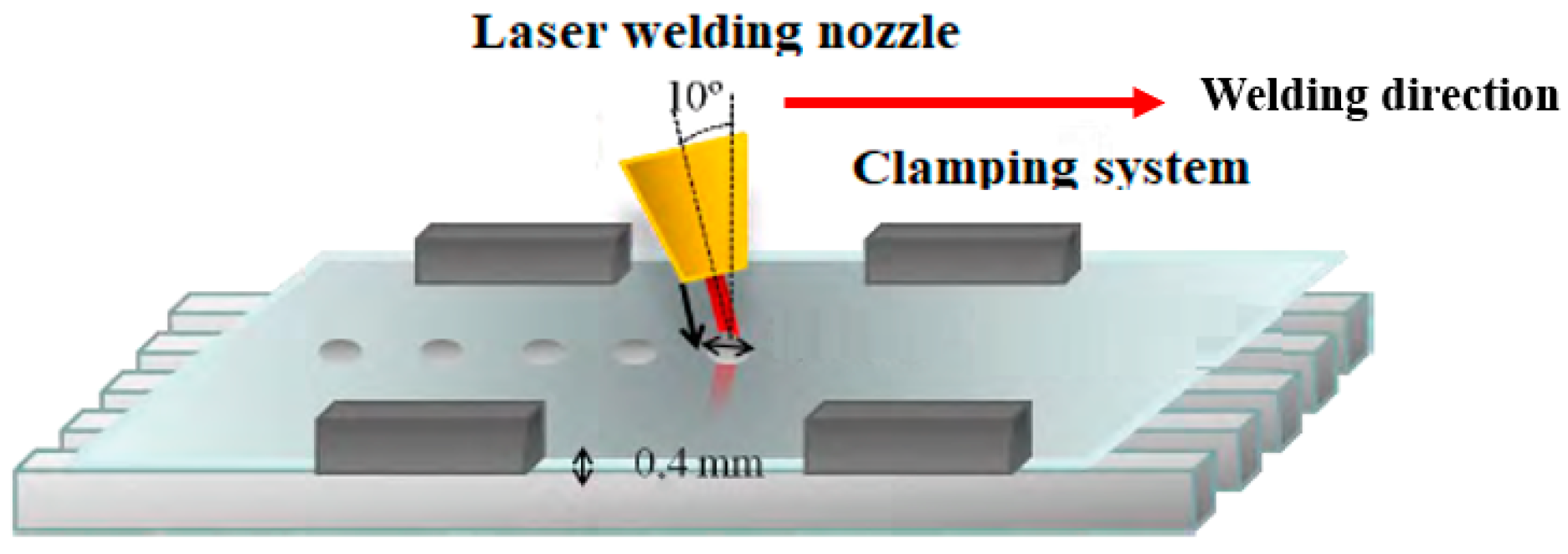
Figure 1 shows a diagram of the process to study the laser pulses. The nozzle has an inclination of 10° with respect to the vertical direction to avoid back reflection to the machine of the reflected radiation. In the case of the welding of a ferric plate with an austenitic one, the plates are overlapped.
2.1. Relation of the Parameters of the Laser Pulse with the Effect on the Material
A pulsed welding is the result of combining several process parameters. They are the beam diameter, Ø, the laser power, P, the pulse duration, t, the repetition pulses frequency, f, and the time within each pulse during which the laser is releasing radiation, known as duty factor (DF). In the case of dynamic pulses, the traversing speed of the laser source, v, constitutes an additional variable. The energy of the pulse, E, can be calculated as the product of the power and the pulse duration.
The measurement of the melted region and the heat-affected zone obtained after shooting the material with pulses with different combination of parameters allows for analyzing the capabilities of the pulses to modulate the welding regime, conduction, or keyhole, and the subsequent consequences of it. One of these is the relation between the area affected by the pulse in the face and bottom of the plate, which determines the overlapping distance between consecutive pulses. A series of pulses to characterize this relation has been carried out with the parameters shown in
Table 2.
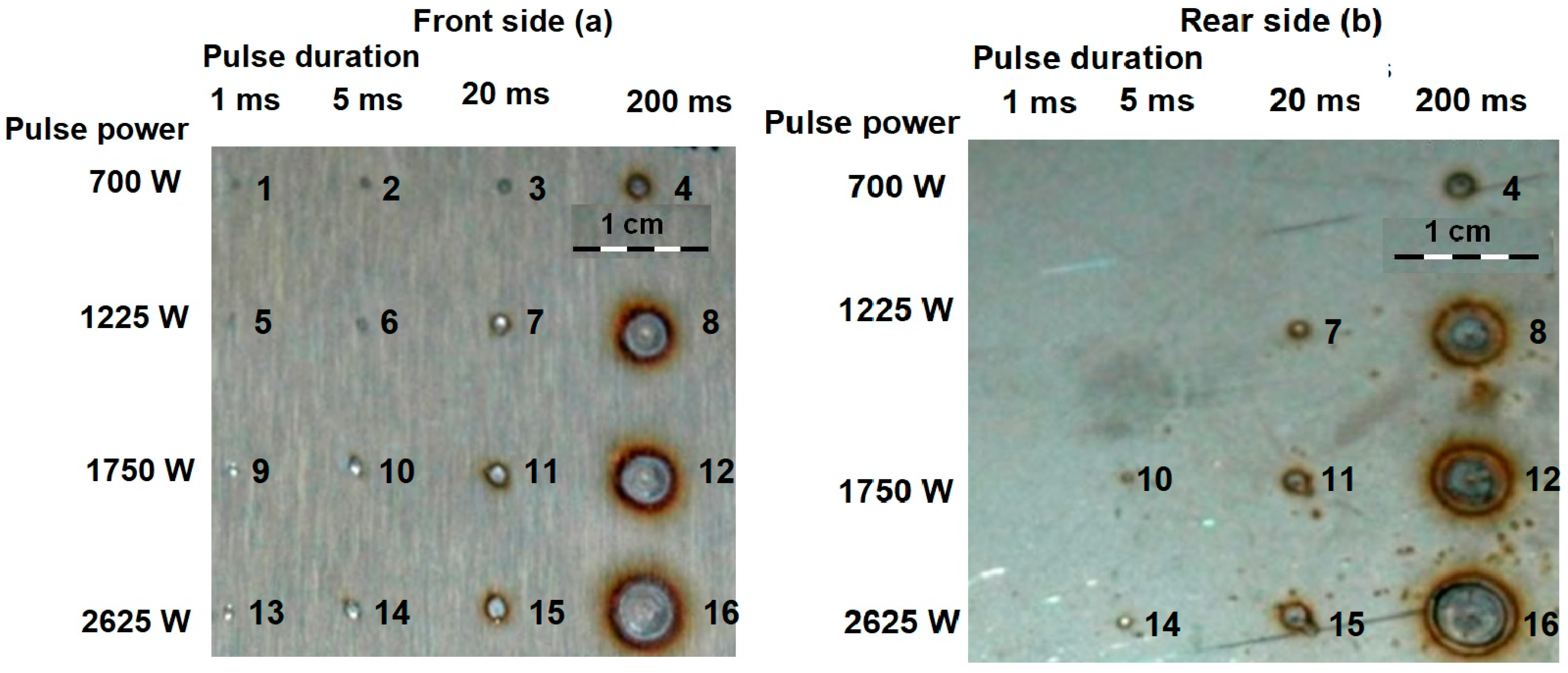
Figure 2 shows the effect on the material in the directly irradiated side
Figure 2a and in the bottom
Figure 2b, using the parameters from
Table 2. Note that at the bottom, depending on the pulse parameters, some affected areas are not visible.
The range of powers and pulse durations in
Figure 2 goes from having no apparent effect on the material to having traversed completely the thickness of the plate and achieved an affected circumference of almost 1 cm diameter, and, therefore, several times larger than the laser beam diameter of 0.4 mm. In addition to providing working windows about the parameters for the laser pulses, the tests in
Figure 2 were able to highlight the mechanism governing heat conduction in the material in each regime. Considering the pulse corresponding to a power of 2625 W and a duration of 20 ms, it has taken place in keyhole regime. This can be stated from observing that it has the same diameter in the face and the bottom, since the plasma grows predominantly in the same direction as the laser-beam propagation. The same level of power of 2625 W, in combination with a pulse duration of 5 ms, has not surpassed the threshold energy to create plasma, and, in this case, the bottom diameter is shorter than the one at the face. The comparison between both situations allows for establishing the geometrical pattern of the cross section of the region affected by the laser pulse in relation with the welding regime.
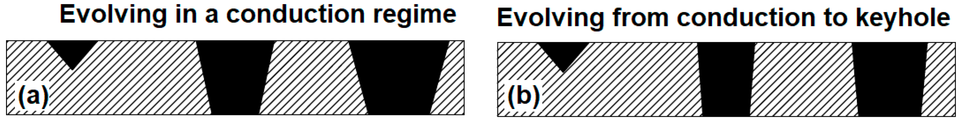
Figure 3 represents schematically the cross section of the welding pool by increasing the energy of the laser pulses always evolving in a conduction regime (left side, from left to right), and evolving from a conduction regime to a keyhole regime (right side, from left to right). While increments of energy in a conduction regime are associated with the growth of both the face and bottom-melted diameters proportionally to the level of energy, when the transition to keyhole regime happens, heat conduction occurs predominantly in the vertical direction, and the melted diameter at the face tends to stabilize, while the bottom affected diameter approaches the face one.
From
Figure 3 it can be seen that in the keyhole regime the welding pool has a more vertical disposition than in the conduction regime. This behavior gives some patterns to minimize the thermal impact in the building of a continuous seam. If the requirement is to achieve a continuously welded seam in the directly irradiated face of a joint and no matter if the opposite face has only separated welded points, conduction regime is acceptable. However, if continuity has to occur in the bottom of the joint, the use of a conduction regime would lead to a tremendous overheating of the directly irradiated face since the bottom-melted diameter is always going to be shorter than the one at the face. Something similar happens with the heat-affected zone. Nevertheless, by using a keyhole regime, the high absorption of the energy in vertical direction makes the bottom diameter approach the one at the face of the plate, and the overheating to achieve bottom continuity is significantly reduced.
These considerations are reinforced if the heat-affected zone is analyzed in
Figure 2. The pulse with a power of 2625 W and a duration of 200 ms has happened in the keyhole regime given the coincidence between the face- and bottom-melted areas. The heat-affected zone in the bottom of the pulse can be seen as an oxide circle around the melted region. In the case of the bottom of the pulse for the cases of 1750 W, 200 ms and 1225, 200 ms, it reveals that these pulses have passed in conduction regime, because of their shorter diameters in comparison with the face. Their oxide circle is bigger compared with the melted area than in the case of the pulse happening in the keyhole regime, where the oxide circle approaches the melted area. Once again, the higher energy efficiency of the keyhole regime led to a larger amount of energy concentrated in the welding pool instead of overheating the surrounding material.
The fundamentals to select the real affected diameter instead of the nominal diameter of the laser beam as a reference to establish the overlapping between consecutive pulses is also clear from
Figure 2. For all the levels of power, the affected area in the material always grows with the pulse duration, or, in other words, with the energy of the pulse.
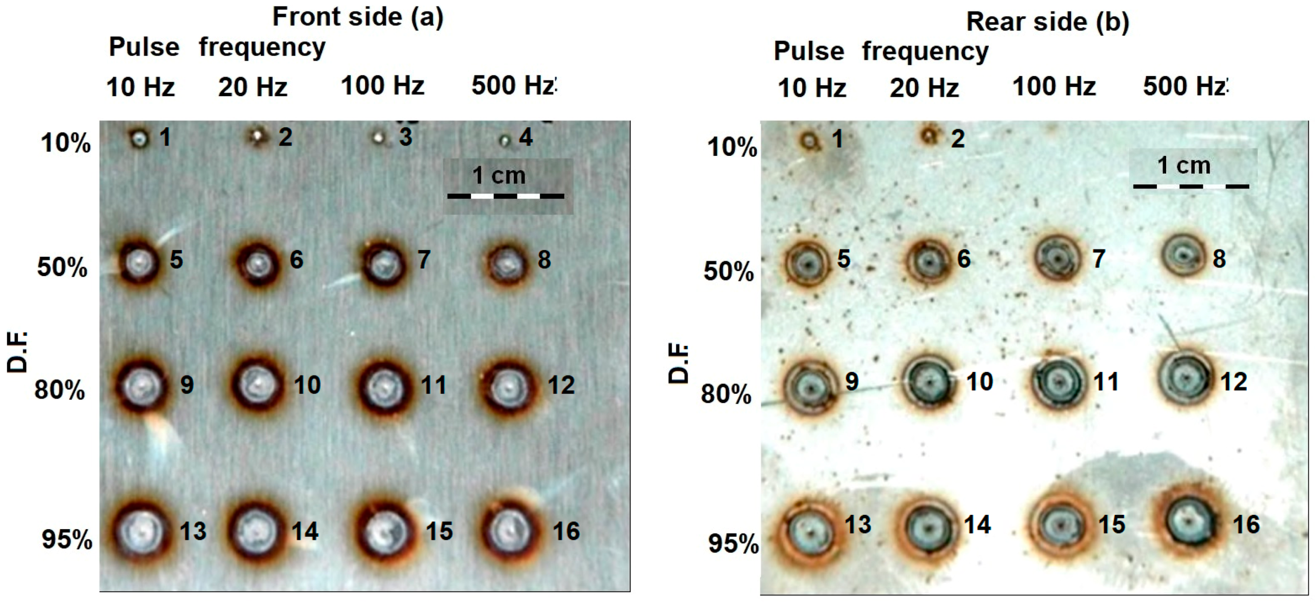
Table 3 contains the process parameters used to characterize the effect of the pulses frequency and the DF with 1750 W of power.
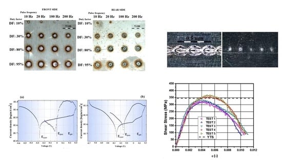
Figure 4 shows the effect of the pulse repetition frequency and the duty-factor percentage on the treated material for a power of 1750 W and a total duration of 200 ms. Note that at the bottom, depending on the pulse parameters, some affected areas are not visible.
The effect of the duty factor is clear from
Figure 4. Since it is the percentage of the duration of the pulse during which the laser is on, the larger value the duty factor has, the larger amount of energy supplied and, consequently, a big area of the material is affected by either the heat-affected zone or welding pool. The pulse repetition frequency represents the number of pulses per second whatever the value of the duty factor is. High frequencies tend to hinder the transition from conduction to keyhole regime. It can be seen in
Figure 4, comparing, for instance, the bottom affected area of the pulses with a duty factor of 50% and frequencies of 20 Hz and 500 Hz. The melted area in comparison with the total affected area (surrounded by an oxide circumference) is bigger for the case with the lowest frequency. A similar behavior can be observed for the remaining tests. The physical basis for this behavior is related with the stability of the plasma, which is more favored with intermediate values of frequency.
The transition of the welding regime, from conduction to keyhole, and the dimensions of the heat-affected zone and the melted area can be modulated, therefore, by adjusting the pulse parameters. Qualitatively, the achievement of a joint with high mechanical resistance, associated with high penetration of the welding pool, and minimum thermal impact, is related with the obtaining of the keyhole regime. It has been shown to be achieved with relatively high values of power and energy of the pulse, and intermediate values of pulse repetition frequency, which, in turn, can be readjusted by means of the duty factor. After this phenomenological approximation to the most favorable pulse parameters, the following step is a quantitative characterization of them, in static and dynamic conditions, to get particular values to introduce in the overlapping factor (OF) formula [
18], in order to get a continuous joint with overlapped pulses with minimum thermal impact.
2.2. Calculation of the Overlapping Distance
The OF is a quantification of the separation between consecutive pulses in relation to diameter of the laser beam, in a classical approach, or in relation to the real dimensions of the affected area in the material affected, in an approach focused on the energy optimization of the joint. In a previous study by the authors [
20], a methodology to calculate the overlapping distance in an energy-optimized way was presented. The current section highlights the main aspects of this methodology in the context of its application to the laser welding of dissimilar steels.
The overlapping factor can be calculated for either static of dynamic pulses. In the static case, the overlapping factor can be trivially calculated as Equation (1) indicates, where Ø is the diameter of the laser beam and
D is the length of the first pulse that was not covered by the next one:
The formula for dynamic pulses must instead consider the elongation of the pulse due to the movement of the thermal source along a distance,
L, equal to the diameter of the laser beam, Ø, plus the product of the process speed,
v, by the time,
t; the term
S represents the length of the first pulse that was not covered by the constative one. Equation (2) offers the overlapping factor for dynamic pulses:
Considering the procedure in Reference [
17], Equation (2) can be operated to make it explicitly dependent on the parameters to define the laser pulse, as Equation (3) shows, where
f is the pulse repetition frequency and DF is the duty factor of the pulse:
A continuous joint by means of overlapped pulses has minimal thermal impact when the overlapping factor is equal to zero, meaning that the contour of each affected area on the material is strictly tangential to the following one. Since Equation (3) is indeterminate given the number of variables, some additional considerations and assumptions have to be introduced as a function of particular requirements, to get the most suitable election of parameters.
Considering the construction of a linear joint along a given length,
L, the linear energy,
EL can be defined as the energy of each pulse,
E, multiplied by the total number of pulses,
NP, needed to cover the prescribed length, as indicated by Equation (4):
The number of pulses needed to cover a given length depends, in turn, on the real dimensions of the affected area in the material.
From the experiments in Reference [
20], prescribed levels of energy were obtained by means of different combinations of power and pulse duration. The cases with pulses of relatively long duration (in the order of 15 ms and 10 ms) needed a relatively short amount of power to achieve a given level of energy. In these cases, the growth of the bottom melted diameter followed a proportional tendency with the increase of power, as typically happens in conduction regimes. When the same levels of energy were obtained with a shorter pulse duration, the amount of power increased, while the growth of the bottom diameter of the pulse followed an asymptotic behavior (stabilization of the size of the diameter despite increasing the power of the laser pulses), which is associated with a typical keyhole regime, where energy absorption happens predominantly in the vertical direction. It means that, for the considered energy levels, the evolution from conduction to keyhole regime happened with pulse durations between 5 ms and 10 ms for the working material used in that study.
Having obtained experimentally particular values for static pulses associated with the different welding regimes, the next step in Reference [
20] was to study the effect of the same values of the pulse parameters in dynamic conditions, where the thermal source experiences a linear movement during the releasing of the laser radiation. Considering the energy levels used for the characterization of static pulses, intermediate values of energy, in the range 10–12 J, were reproduced in dynamic conditions analyzing both the effect of a relatively low advancing speed of 100 mm/s and a relatively high advancing speed of 200 mm/s.
For pulses with a relatively low process speed, the obtained bottom diameter was larger than the equivalent static pulse with the same energy and pulse duration. It is associated to the relation between power density. While with static pulses a saturation effect happens due to a plasma-shielding effect, in the case of 100 mm/s, the dissipation of the plasma is more favored and the shielding effect disappears. Additionally, the speed of the process provides momentum to the welding pool, which assists penetration in the bath. For the case of the highest process speed, 200 mm/s, the bottom diameter had a tendency to diminish. In this case, the higher speed of the process does not favor the stability of the plasma, and, consequently the penetration is poorer.
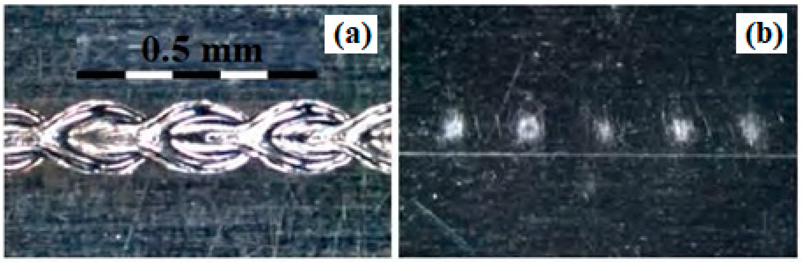
In the case with the shortest pulse duration, when it was applied with a speed of 100 mm/s, the profile corresponds to a typical keyhole behavior with a small heat-affected zone and high penetration. The movement of the welding pool made the molten metal displace to the sides of the welding. When the linear speed increased, some distortion appeared affecting the regularity of the welding pool and the profilometry. This is due to the appearance of projections from the destabilization of the plasma. This phenomenon may lead to mechanical problems like pores, irregularities, and spattering. The situation in Reference [
20] where a level of energy of 12 J was achieved with a pulse duration of 10 ms gave place to a keyhole with lower energy concentration than the case with 5 ms. In these circumstances, there is no a surplus of energy capable of maintaining the plasma pressure enough to laterally displace the molten mass. Because of this, the welding pool decreases in the transversal direction to the advancing direction, when the speed increases. The contraction of the keyhole is associated to a poorer conduction of the heat to the base of the welding pool, affecting the depth reached by the welding. However, the narrowing of the keyhole has the advantage of preventing the welding pool from creating spattering and drops.


