Incremental Forming of Titanium Ti6Al4V Alloy for Cranioplasty Plates—Decision-Making Process and Technological Approaches

 , , ,
, , ,
Abstract
:
1. Introduction
2. Materials and Methods
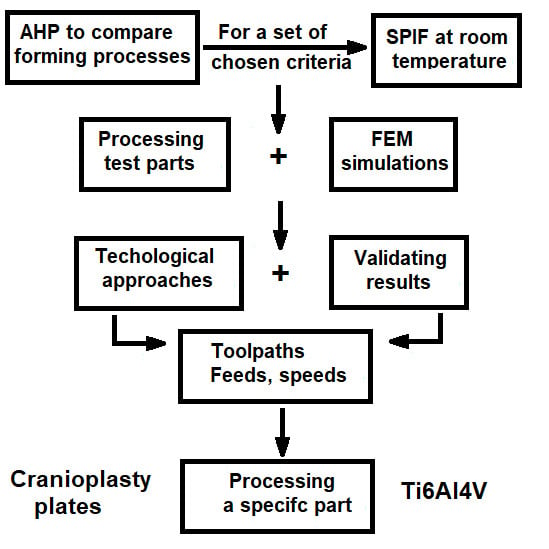
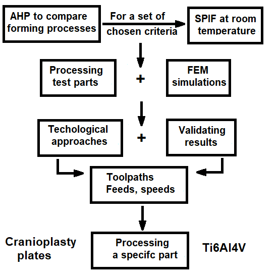
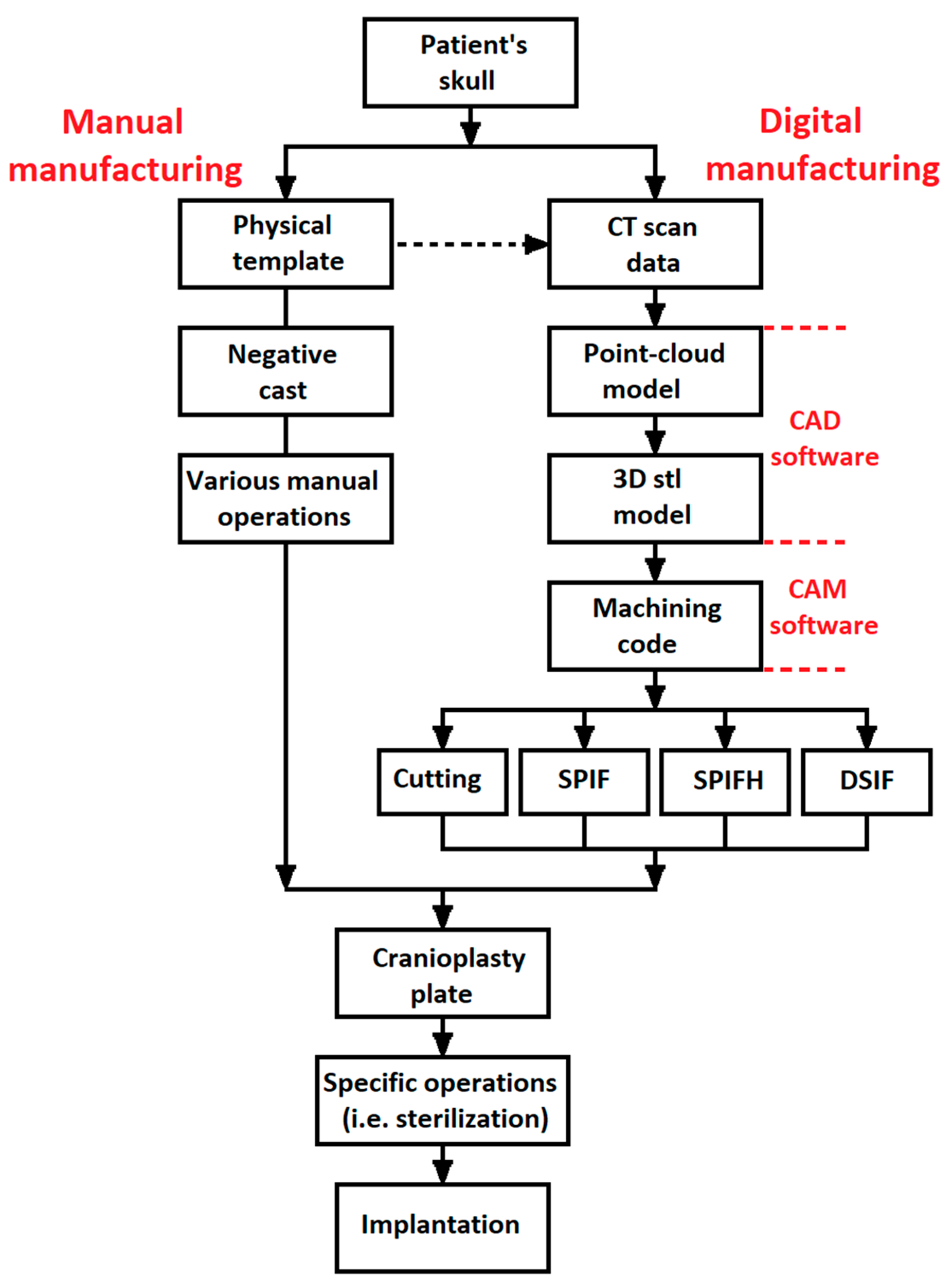
2.1. Decision-Making Process
- C1—Formability: seen here as the ability of the manufacturing process to modify the shape of the workpiece by redistributing the material (plastic deformation). It is noticeable here that three of the analyzed processes are plastic deformation processes, while one of them (CUT) is based upon shaping the part by removing material. However, it was considered that this criterion could be also applied to the CUT process;
- C2—Microstructure: seen here as a measure of how the microstructure of the material is affected by the manufacturing process and, consequently, how the biocompatibility of the processed part could be affected;
- C3—Degree of control: seen here as a measure of how the parameters of the process and the shape and dimensional parameters of the parts (cranioplasty plates) can be controlled;
- C4—Roughness: the meaning of this criterion is quite straightforward, as it expresses the surface quality achievable for the processed parts;
- C5—Energy consumption: it is related with the amount of energy required by each manufacturing process;
- C6—Accuracy: seen here as the maximum achievable accuracy for the parts processed by each of the analyzed manufacturing processes;
- C7—Production time: seen here as the total amount of time to produce a cranioplasty plate.
- -
- Microstructure (C2) and formability (C1) are very important characteristics of a cranioplasty plate; however, for a device in contact with the human tissue, the state of the microstructure should be considered weakly more important that the ability of shaping the plate;
- -
- The degree of control (C3) is a measure of the quality and repeatability of the process. A higher degree of control will allow the process to be automated, but, finally, for a prosthetic device (which can also be manufactured manually), the ability to shape the plate exactly as required (C1) is strongly more important;
- -
- Roughness (C4) of the part is also important for a prosthetic device, but while the microstructure cannot be repaired if affected by the manufacturing process, roughness could be improved (even by manual operations); thus, the formability of the plate (C1) should be considered weakly more important;
- -
- Energy consumption (C5) should be reduced as possible for any manufacturing process; however, when it comes to cranioplasty plates (which usually are manufactured as prototypes), the ability of shaping the part should (C1) be considered demonstrably more important than saving energy (C5);
- -
- Manufacturing accuracy of the cranioplasty plate (C6) is important, but from the point of view of its functional role (prosthetic device, which is not moving or being in contact with other moving parts), the formability (C1) should be considered weakly more important;
- -
- Production time (C7) is a measure of the efficiency of a production process, but taking into consideration of the fact that, as stated for the (C5) criterion, the cranioplasty plates are manufactured as prototypes, the (C1) criterion should be considered strongly more important.
- -
- Cranioplasty plates are manufactured starting from a sheet metal workpiece; thus, a plastic deformation process (SPIF) should be considered as an intermediate between equally important and weakly more important than a cutting process (CUT) from the point of view of formability (C1). Even the workpiece is different for cutting, and cutting also allows the user to machine complex shapes; thus an intermediate value has been considered;
- -
- Ti6Al4V alloy is known as a low-formability material, and heating it leads to an increase in the formability. However, applying heat could lead to some problems described above. Thus, SPIFH should be considered weakly more important than SPIF, from the (C1) point of view;
- -
- Using a master–slave tools layout with punch and counter-punch will significantly improve the formability of the part, but will also lead to the use of very complex layouts and equipment; this is why DSIF should be considered weakly more important than SPIF, from the (C1) point of view.
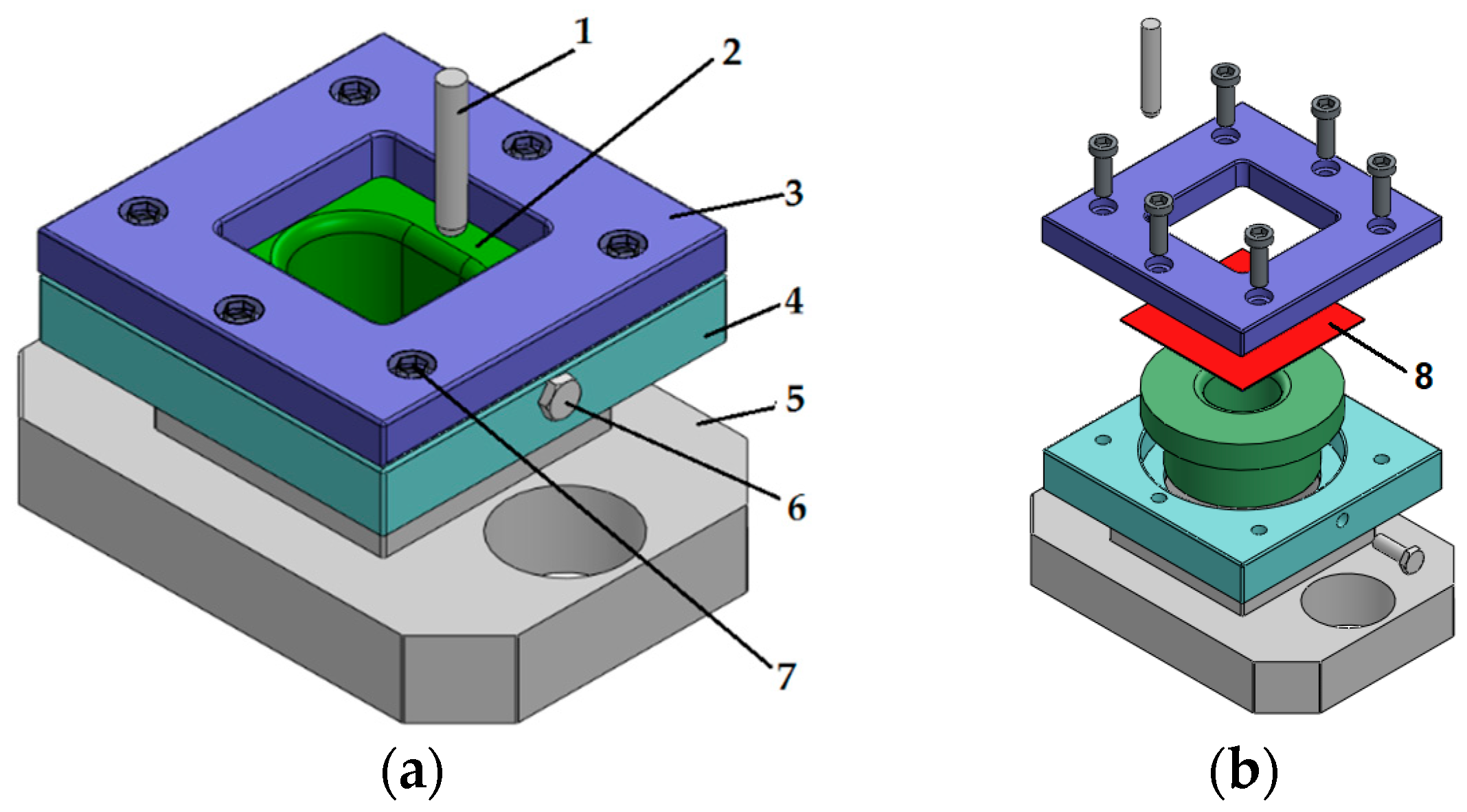
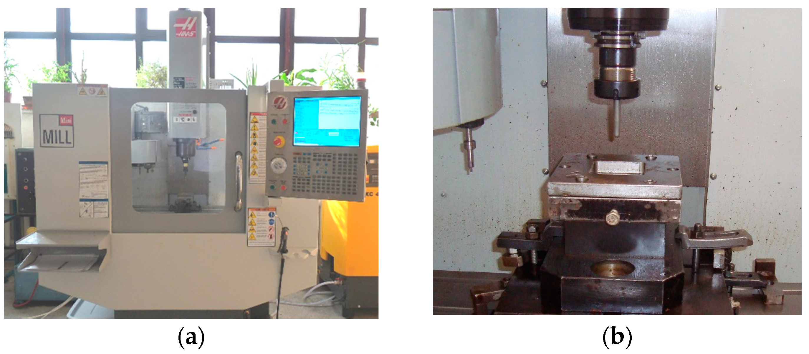
2.2. Experimental Layout
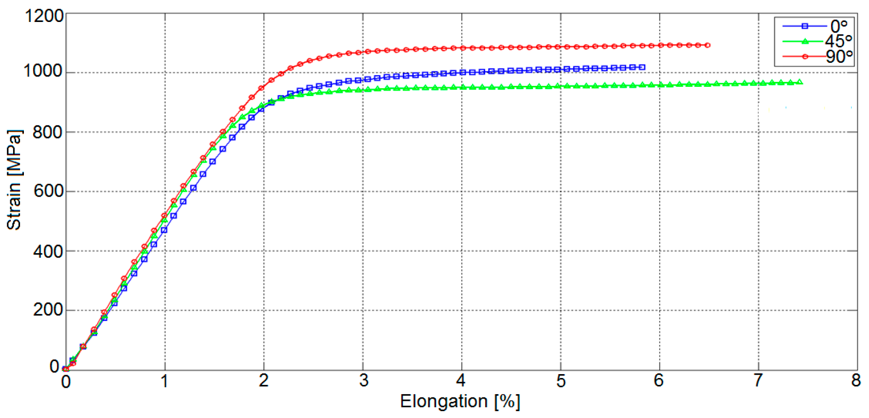
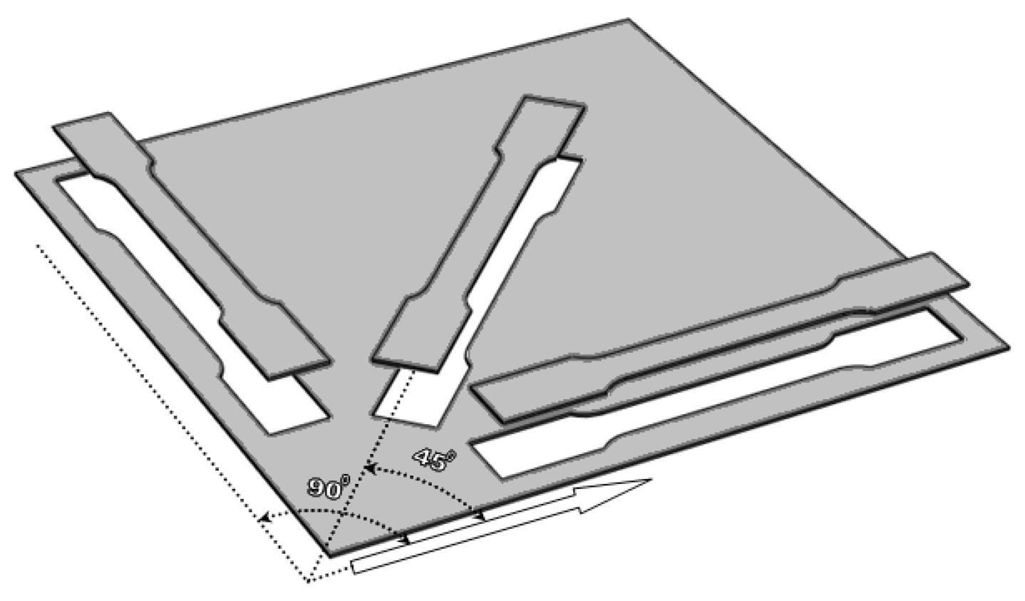
2.3. Material
- tensile testing machine Instron 5587;
- optical strain measurement system GOM Aramis.
- modulus of elasticity E [MPa],
- flow limit Rp0.2 [MPa],
- tensile strength Rm [MPa],
- hardening coefficient n [-],
- resistance coefficient K [Pa],
- elongation εmax [%].
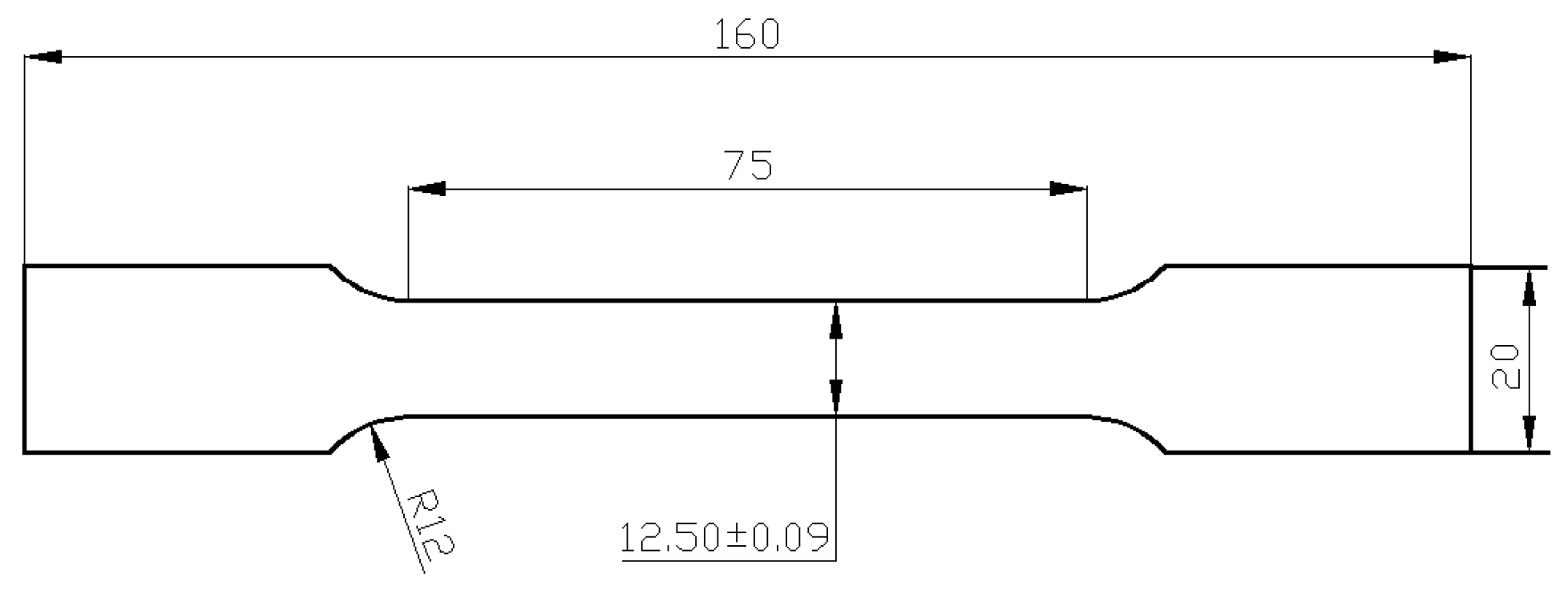
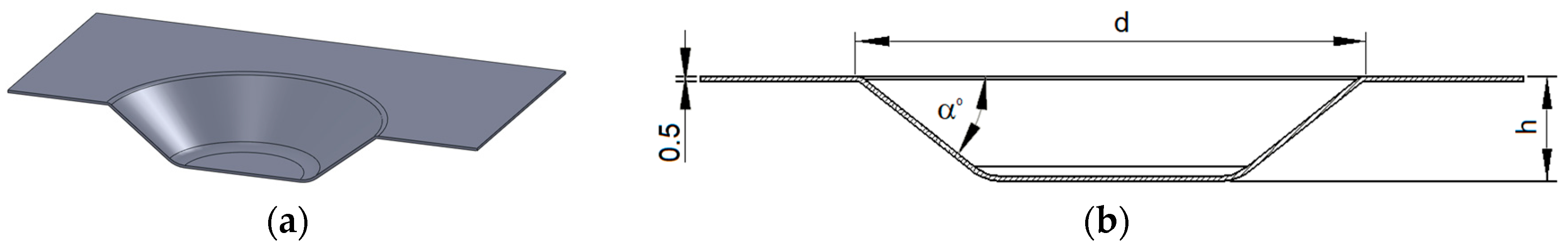
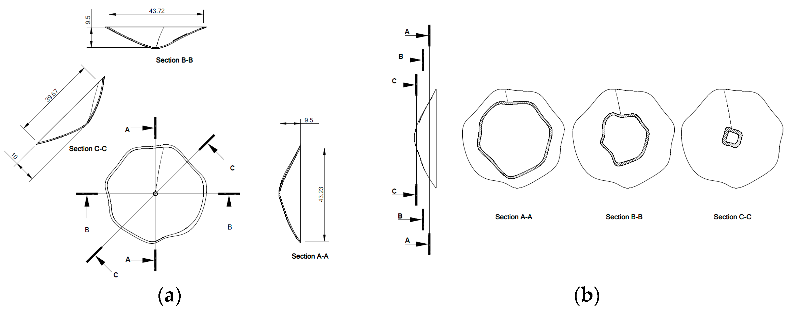
2.4. Shape of Test Parts
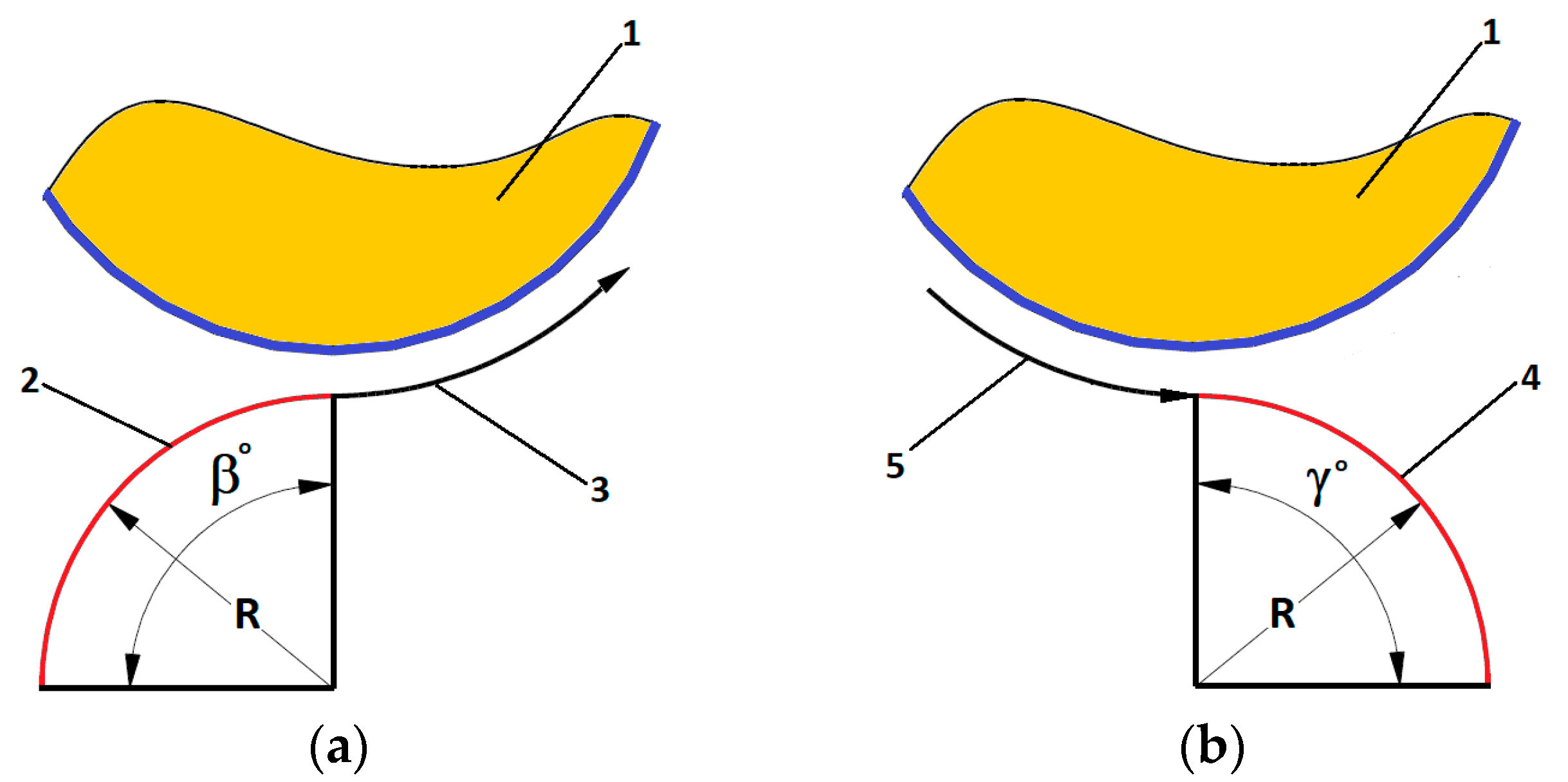
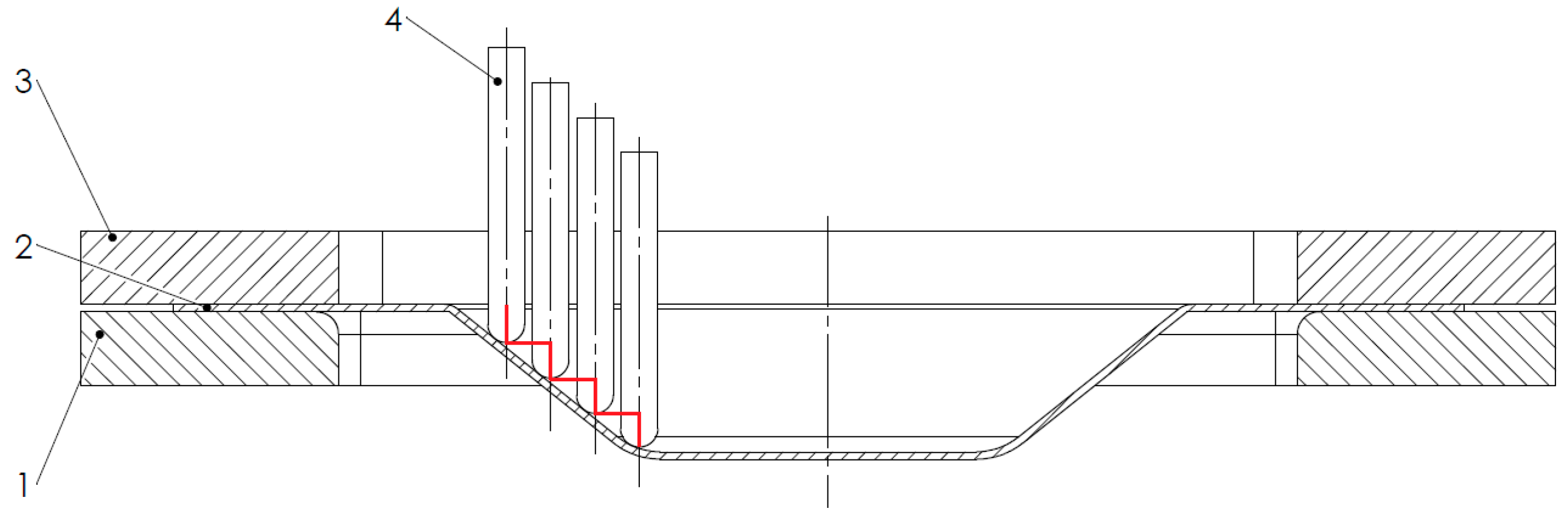
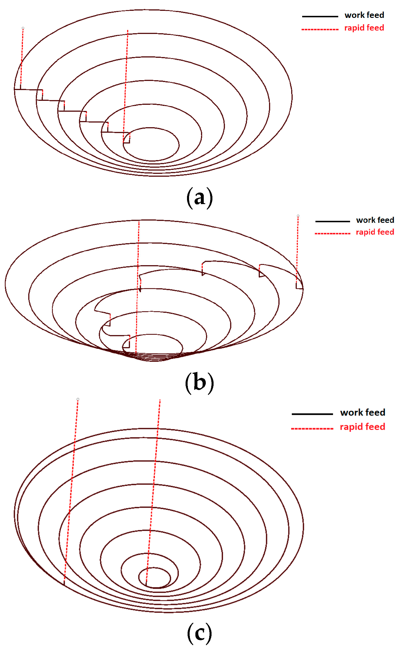
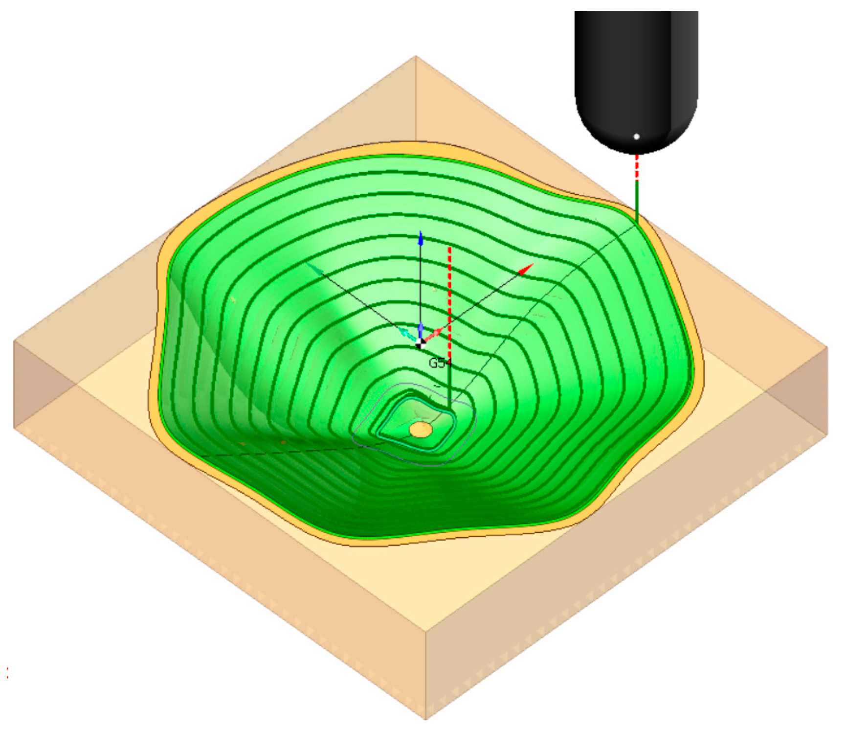
2.5. Processing Trajectories
- contour-curves-based trajectory (a contour curve is obtained by intersecting the 3D shape by an XY plane—for the truncated cone, the contour curve is a circle);
- spatial spiral trajectory.
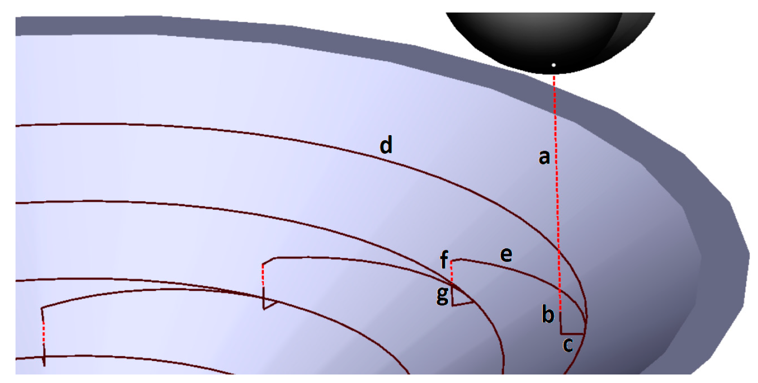
- -
- the punch approaches on the Z axis with rapid feed (a);
- -
- the punch continues the approach on the Z axis with work feed, until it reaches the contour curve level (b);
- -
- the punch follows the approach path, in an XY plane at the Z level of the contour curve, until it is positioned on the contour curve (c);
- -
- the punch follows the contour curve (d);
- -
- the punch follows the retraction path, in the XY plane situated at the Z level of the contour curve (e);
- -
- the punch approaches on the Z axis with rapid feed, travelling to the next contour curve (f);
- -
- the punch continues the approach on the Z axis with work feed, until it reaches the next contour curve level—a new XY plane (g);
- -
- after phase (g), the movements are repeating in a cycle, from d to g, until the last contour curve is processed.
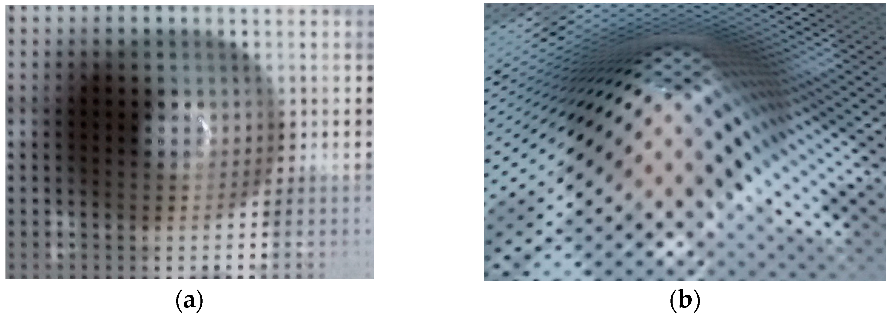
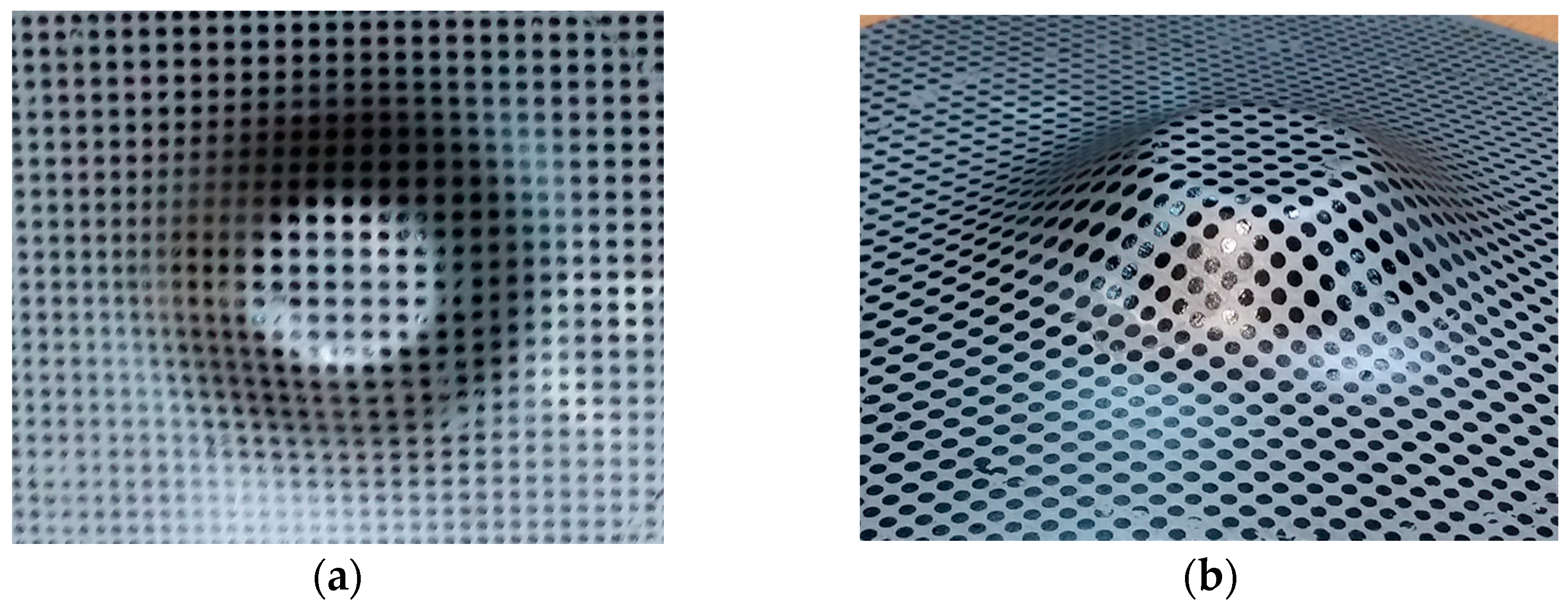
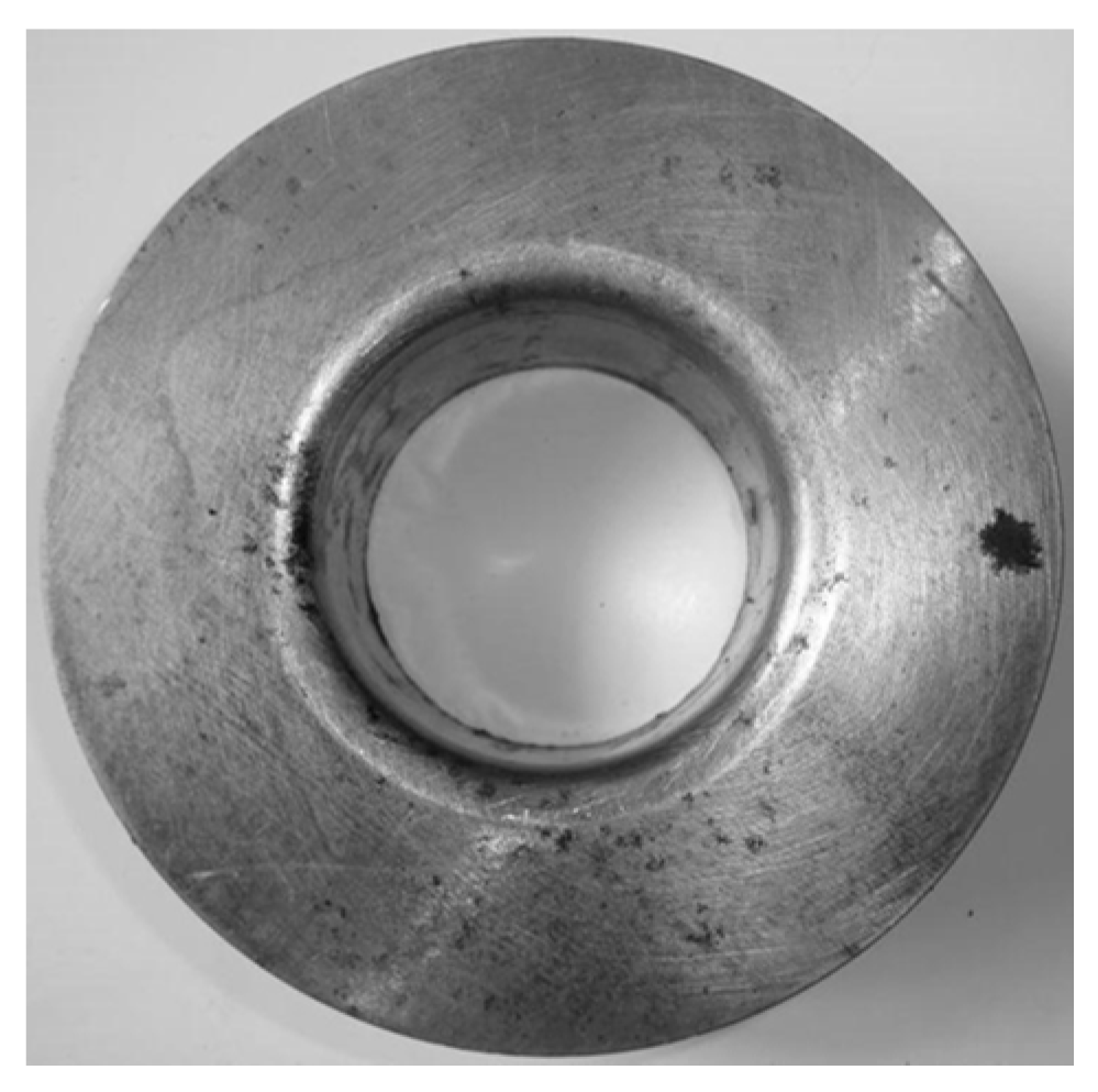
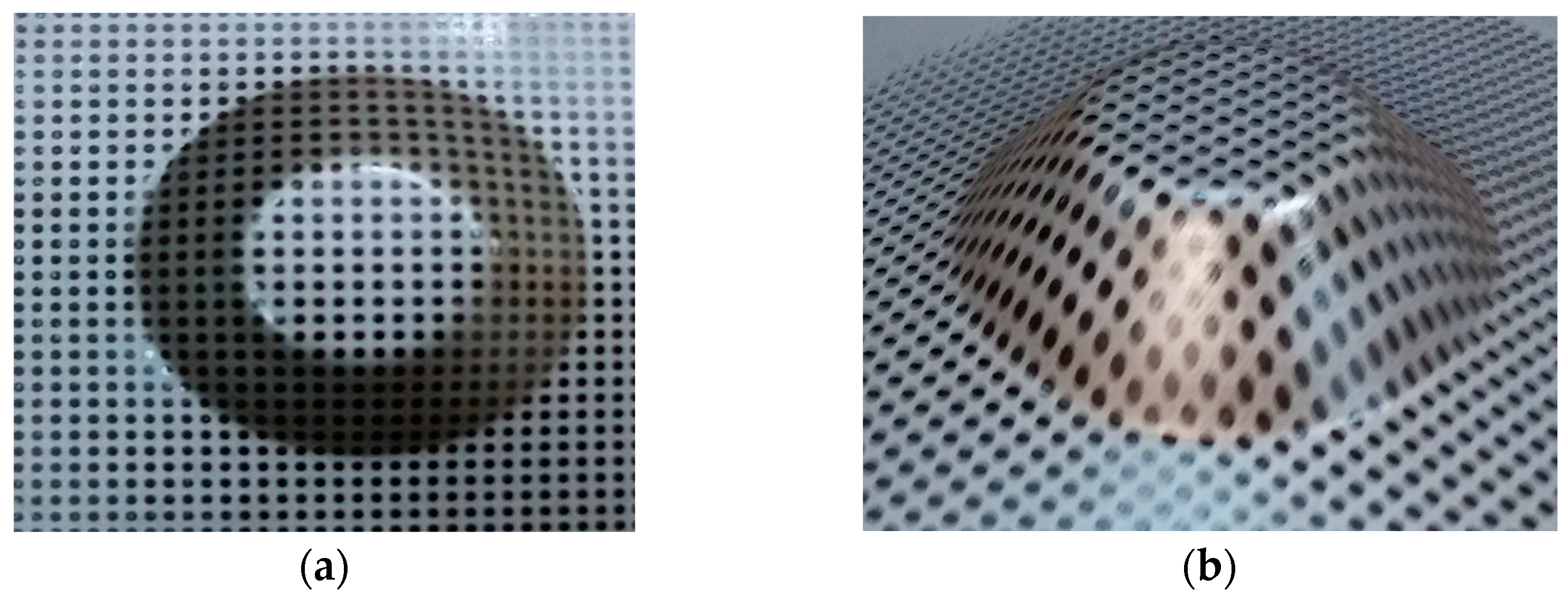
2.6. Processed Parts
- The working feedrate was fixed to 150 mm/min;
- The punch was fixed in the main spindle of the machine and driven with a rotational speed of 150 rev/min around its own axis. According to the literature review, this rotation reduces the friction and has a favorable influence upon the formability of the material. However, the rotational speed was limited to avoid the heating of the material, which could affect its formability. The temperature limit in this case is 400 °C. At 150 rev/min, the temperature (measured during the process with an FLIR TermoVision A320 thermal imaging camera (manufactured by FLIR Systems, Inc., Wilsonville, OR, USA) was found to be lower than 100 °C;
- The starting angle of the truncated cone was set to 30°, the next one was 35°, and afterwards the angle was incremented by 1°;
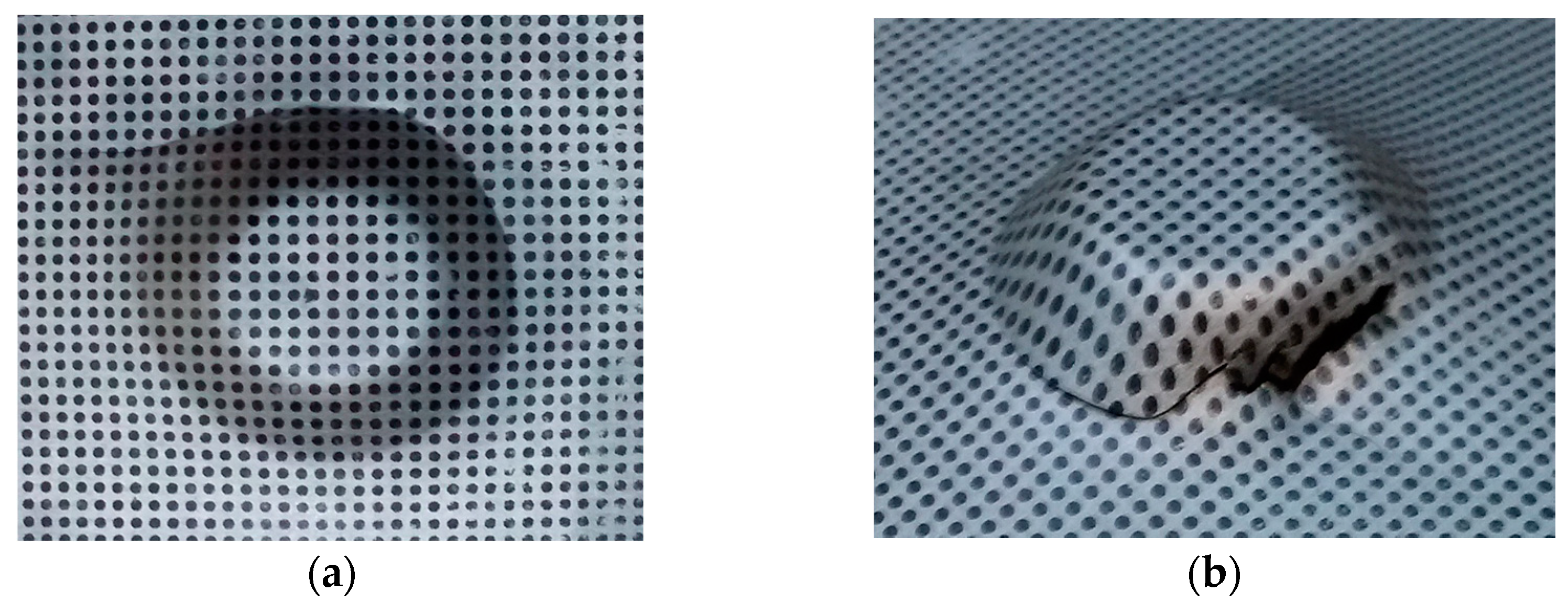
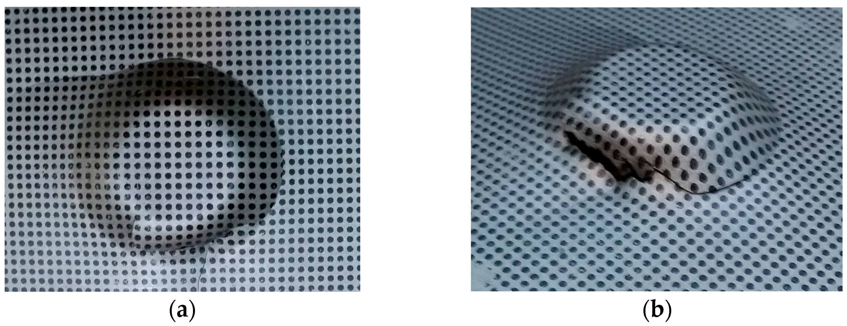
- Three vertical steps were considered: 0.2, 0.4, and 0.6 mm. Smaller steps, i.e., 0.1 mm were considered too small to be considered from a technological point of view, while steps greater than 0.6 mm lead to crack occurrence events at an angle of 30°;
- Two punch diameters were considered: 8 and 10 mm;
- Mineral oil was used as lubricant;
- At each angle, the first approach involved the use of the simplest trajectory (CT). If for a given angle this trajectory failed (crack occurrence), the CTSE was used instead. If the latter failed also, the ST trajectory was considered;
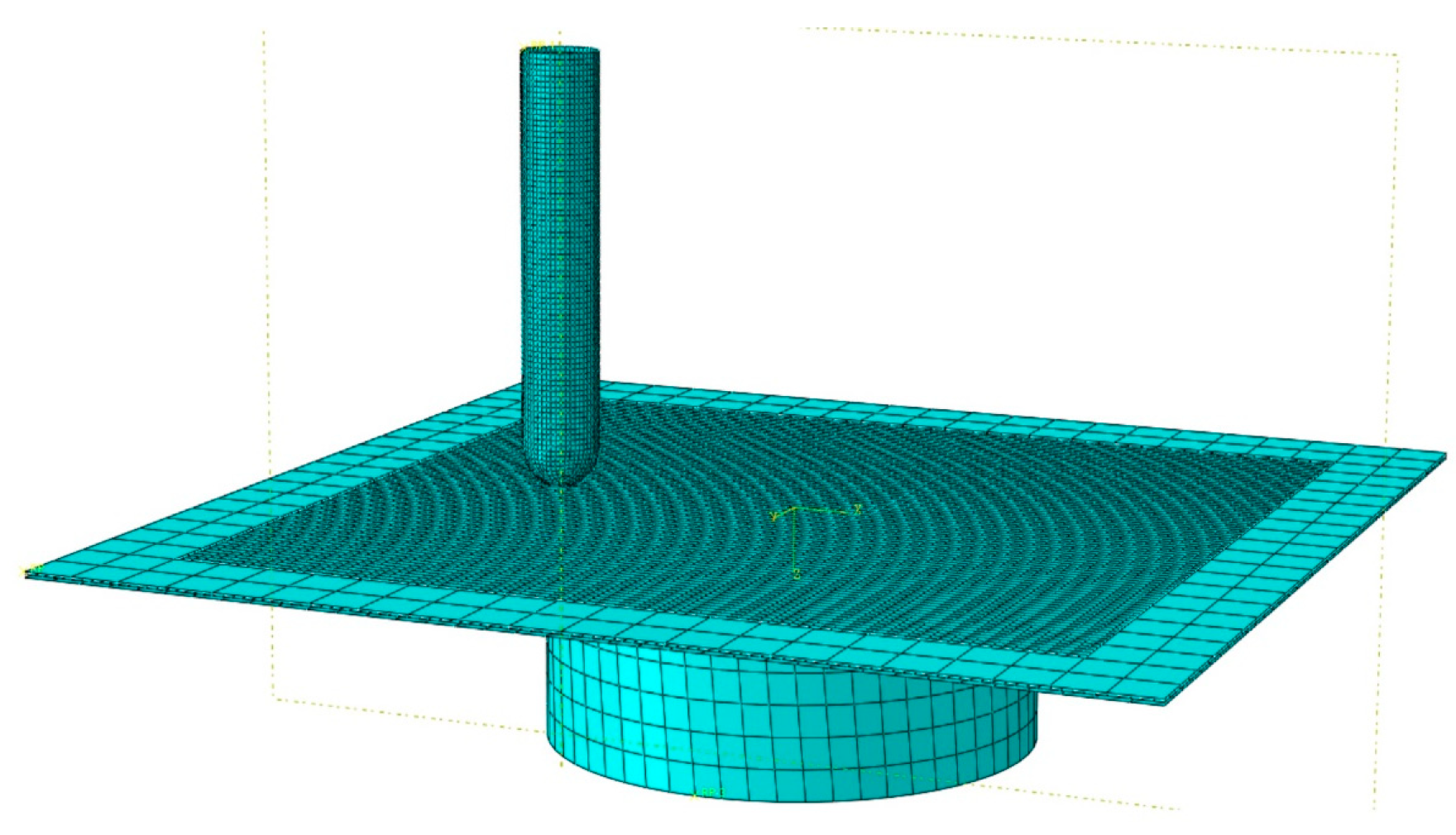
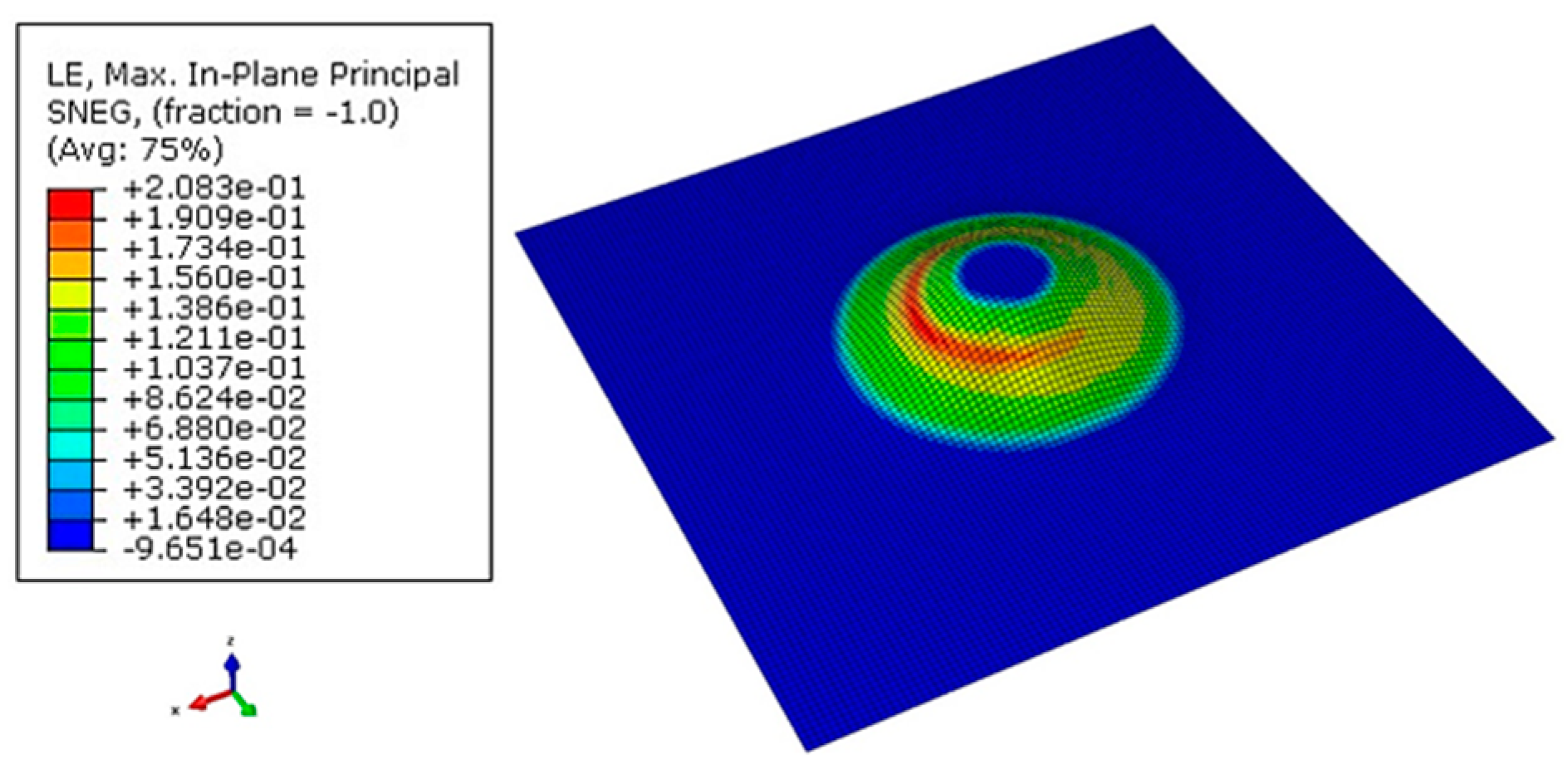
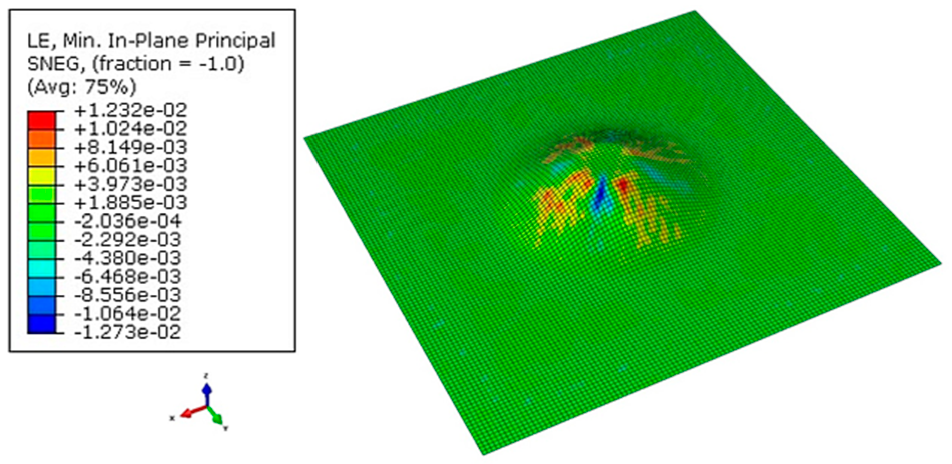
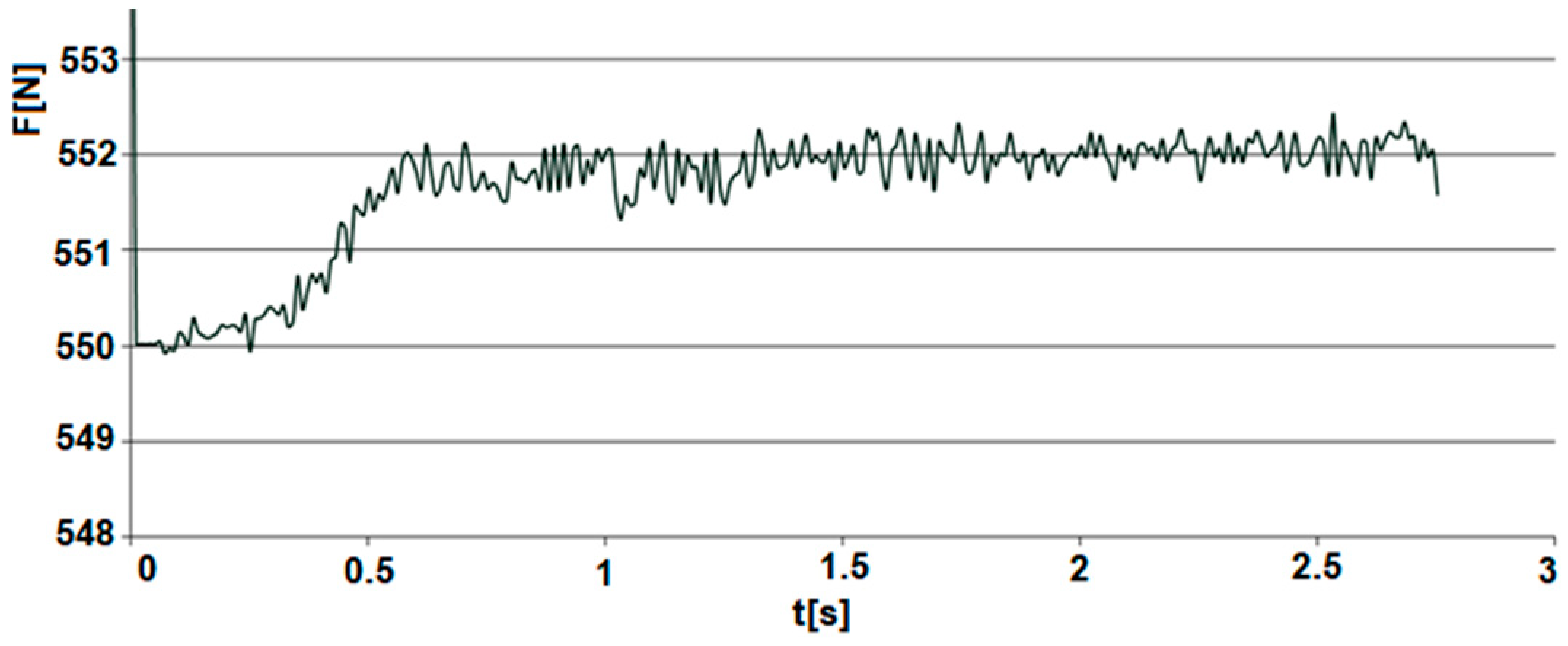
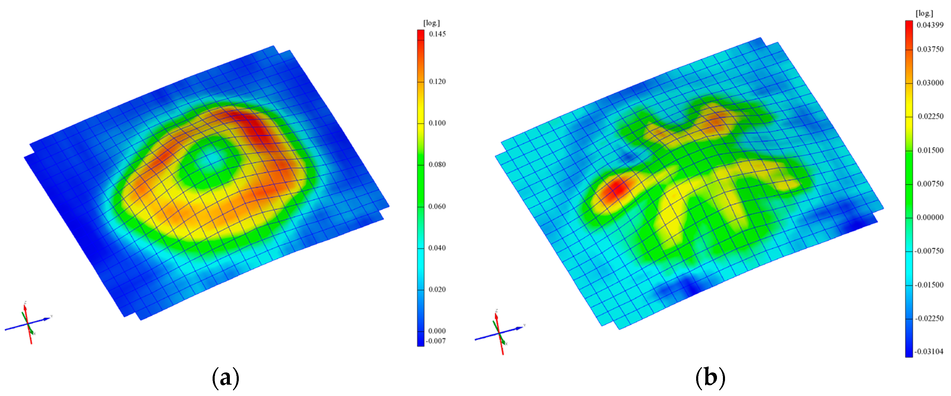
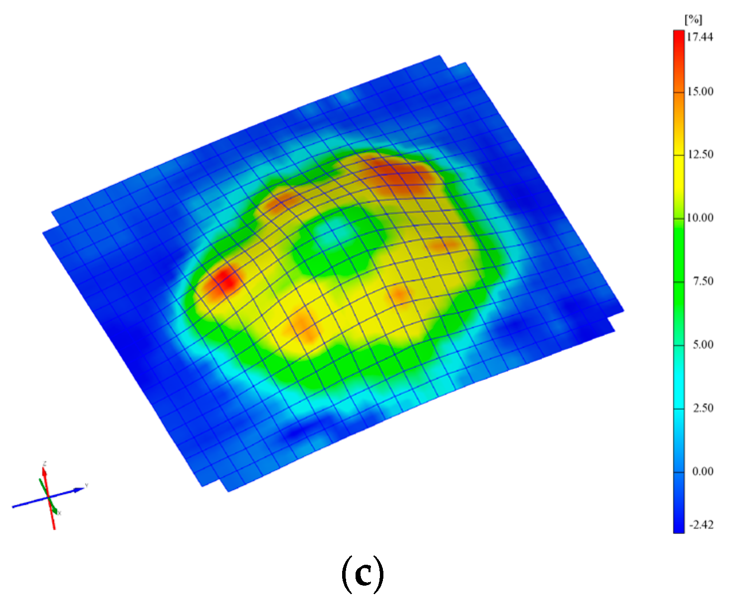
2.7. FEM Analysis
- major strains (ε1);
- minor strains (ε2);
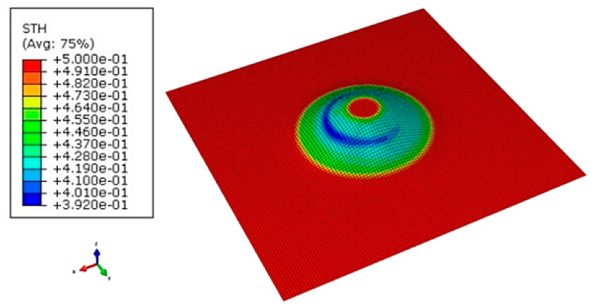
- thickness reduction (smax);
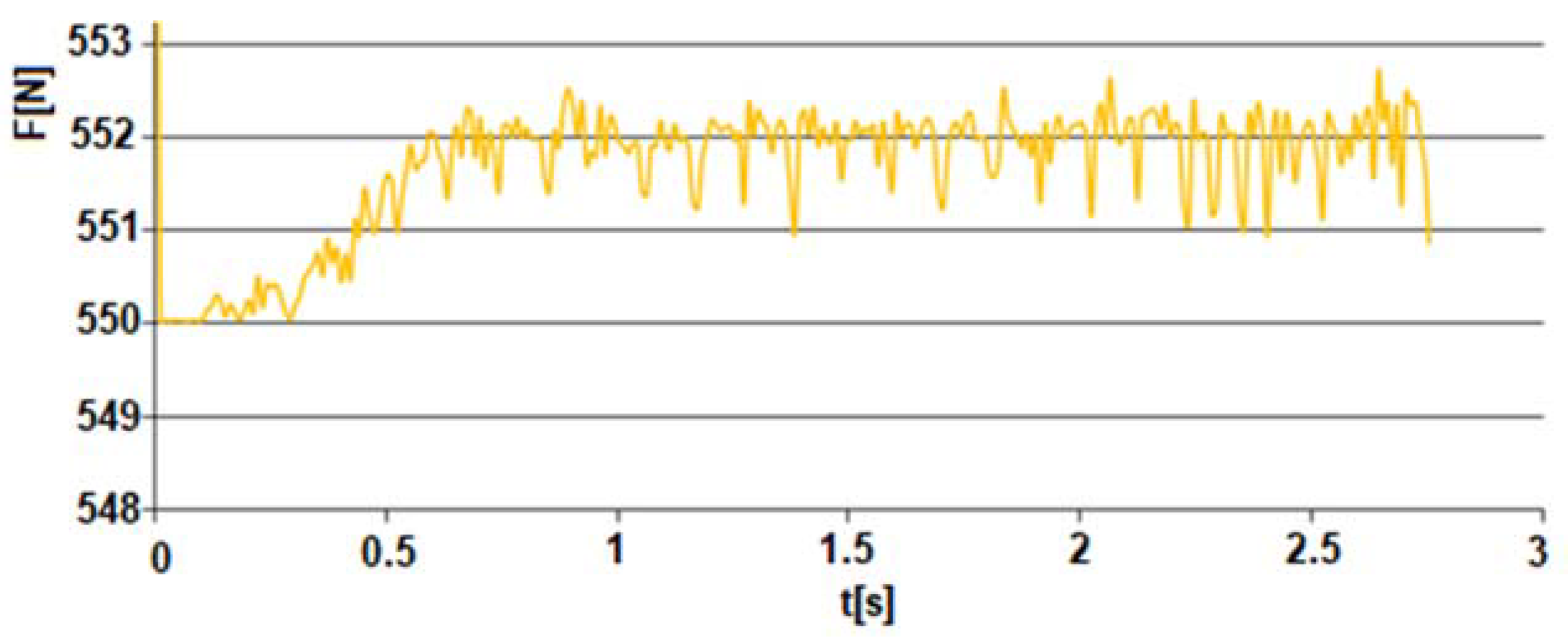
- evolution of the forming force on Z axis.
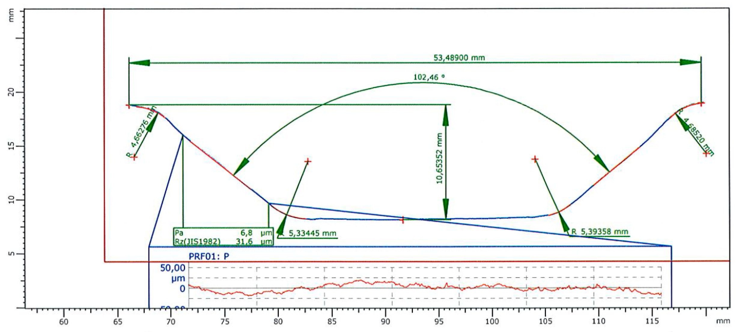
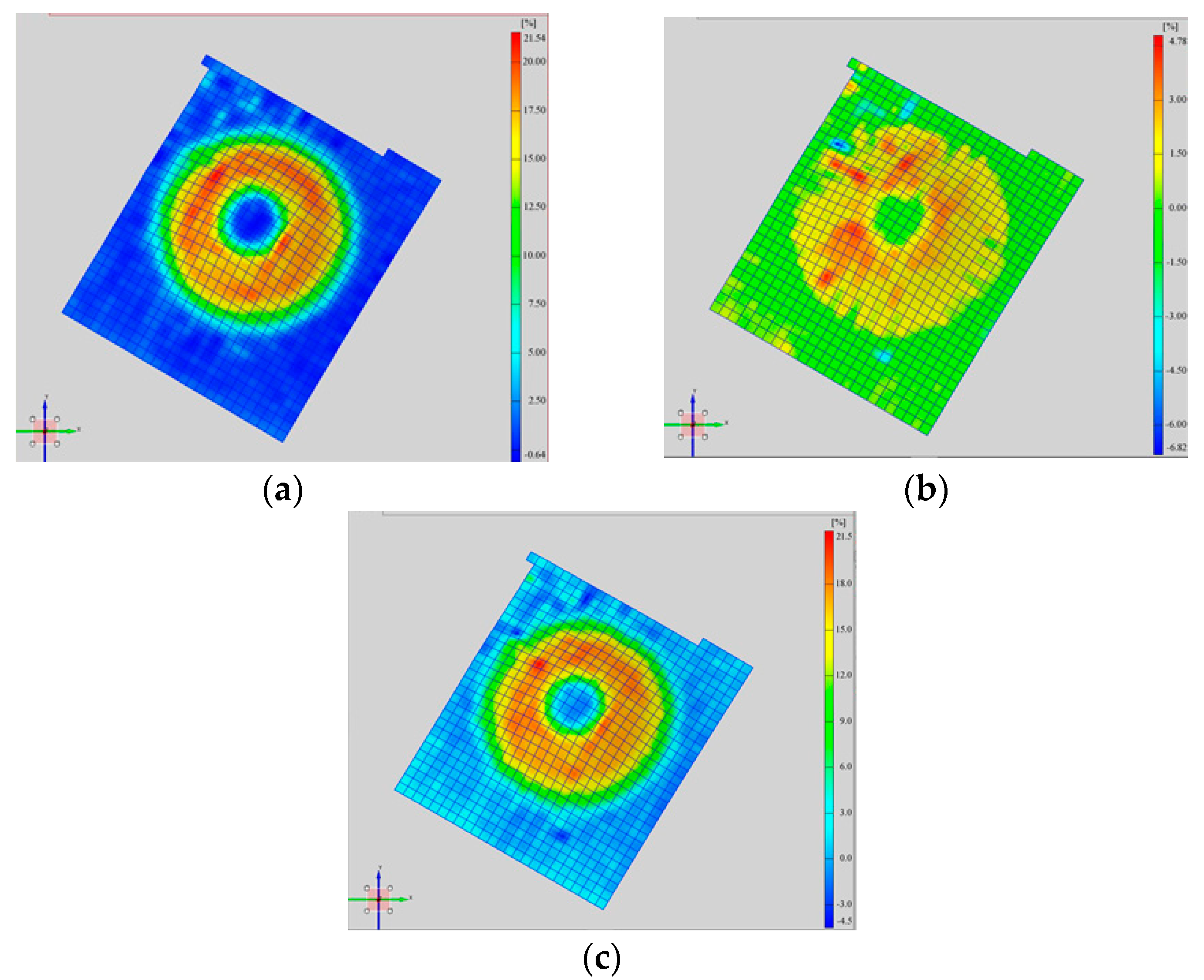
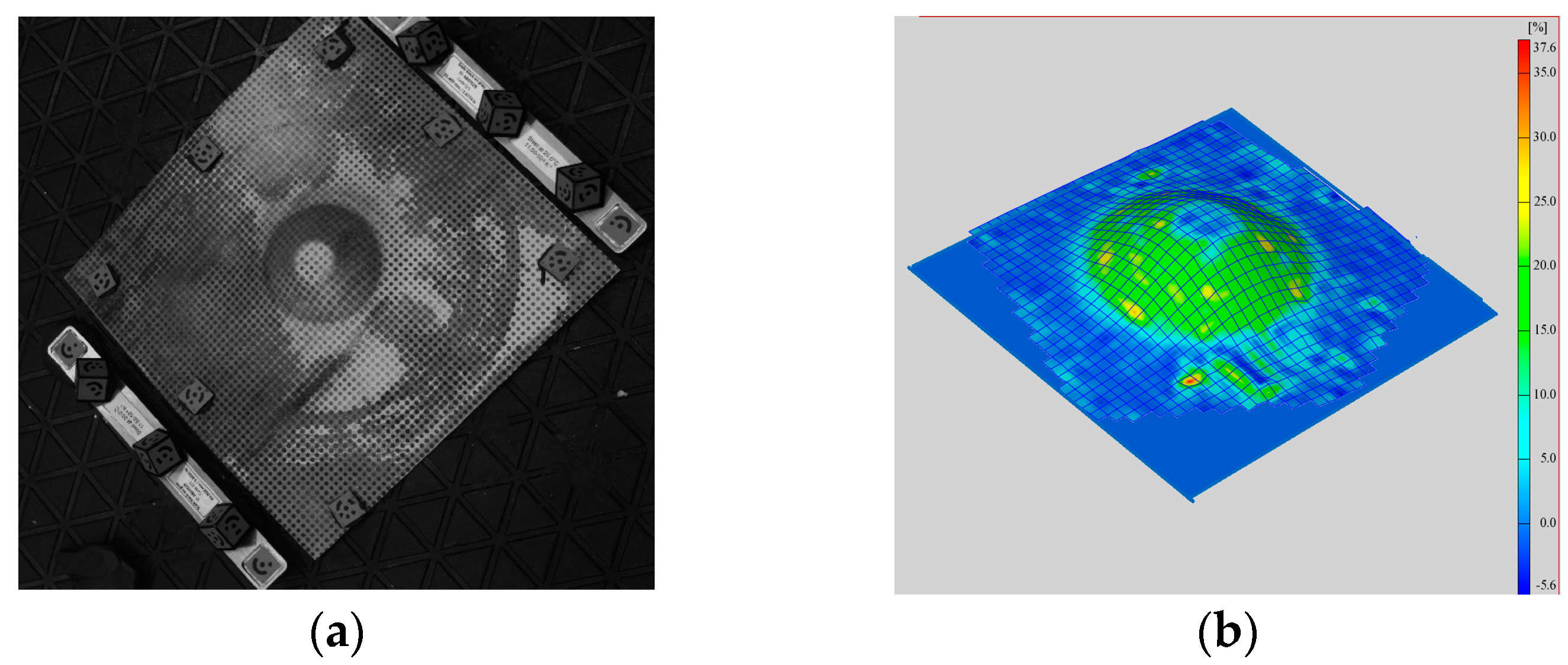
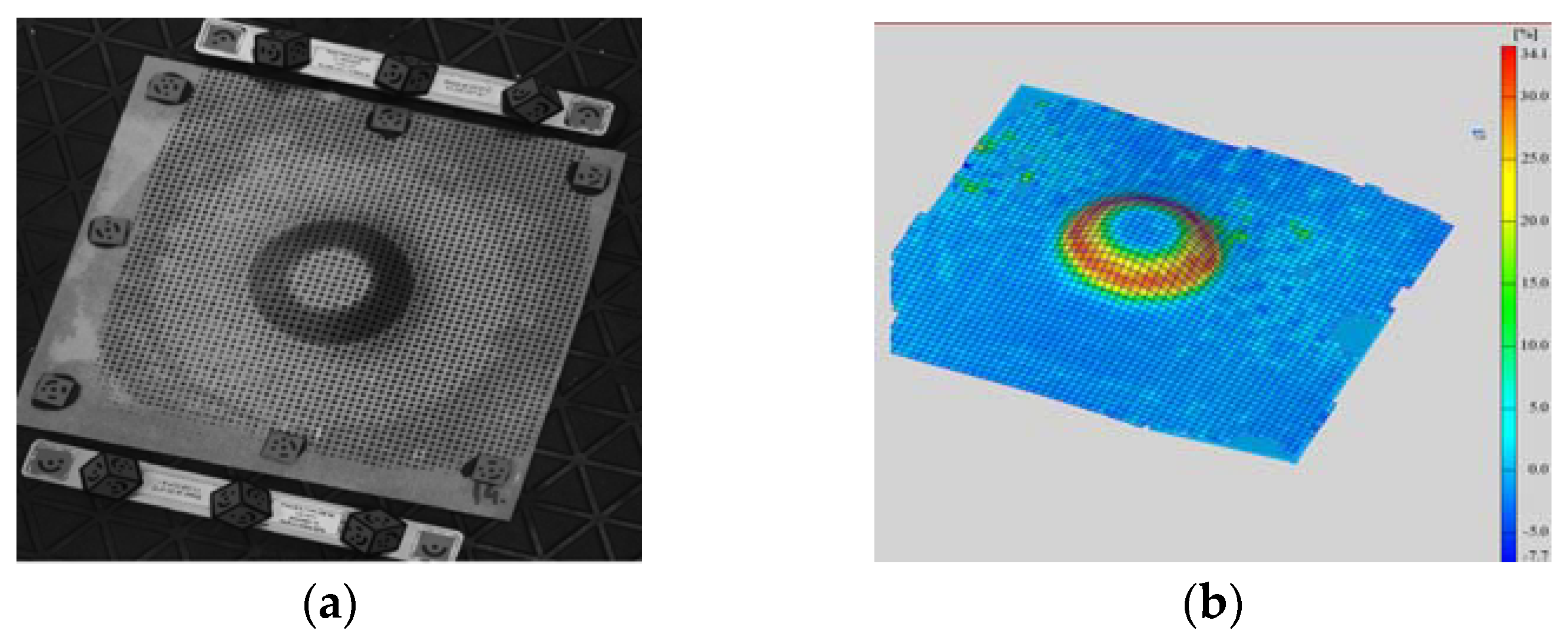
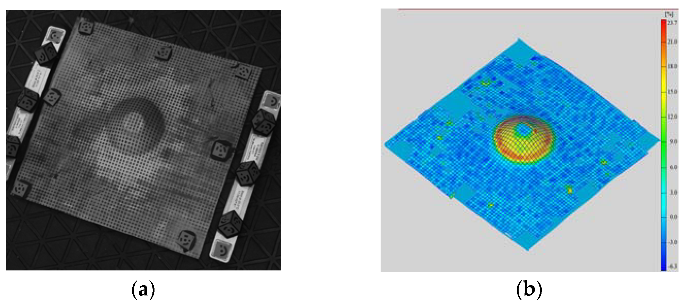
2.8. Experimental Measurements
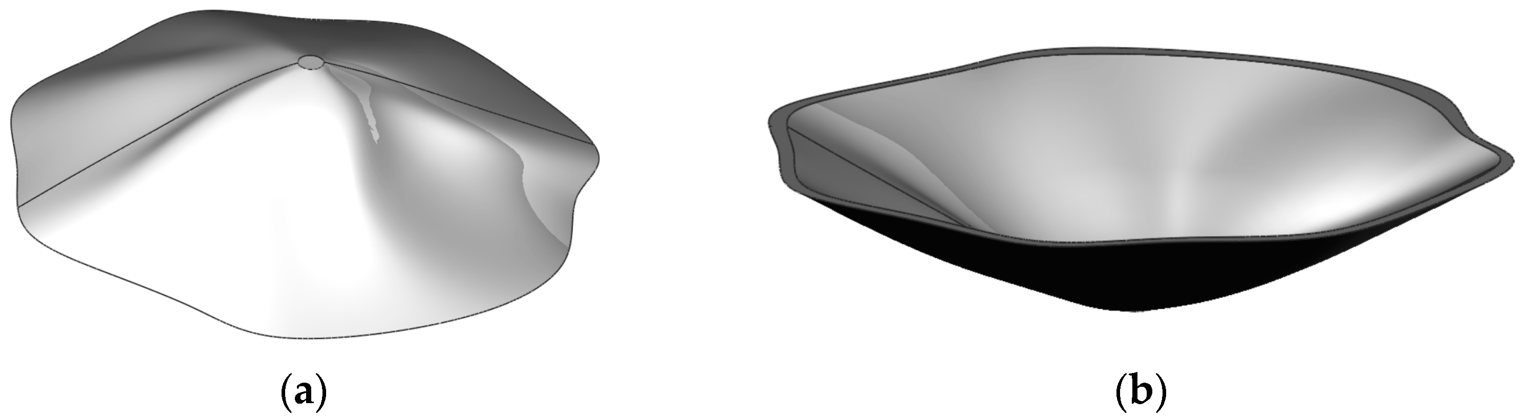
2.9. Manufacturing a Cranioplasty Plate
- The shape of the model had to be highly irregular, to mimic as close as possibly the human skull;
- The shape of the model had to present rapid variations of the wall shapes and angles;
3. Results
- The processed test parts have limited dimensions (due to the available experimental layout), so it should be demonstrated by further study that the findings are also valid for bigger parts;
- Latest results presented in the literature [38,39] have indicated, by means of a cytotoxicity test, that heating the Ti6Al4V alloy during the SPIF process does not affect its biocompatibility. Corroborated by the superior plastic behavior of the heated material, these results narrow the application range of SPIF at room temperature. However, there are still reasons favoring the approach of SPIF at room temperature, from the points of view of roughness, costs (related to equipment complexity and energy consumption), and degree of control.
4. Conclusions
- To reduce friction, the punch must rotate around its axis. A rotation speed between 150 and 300 rev/min was found during this experimental work to be appropriate;
- Theoretically, the working feed does not influence the formability of the part; however, it was found that working feeds greater than 200 mm/min may lead to crack occurrence. However, working feed affects the productivity, which is not critically important for this kind of part. Cranioplasty plates are manufactured as prototypes, productivity having less importance from this point of view;
- The vertical step of the punch (no matter if circular or spiral toolpaths are used) must be smaller than 1 mm. Best results were achieved by using vertical steps of 0.6, 0.4, and 0.2 mm. A direct link was noticed between the vertical step and the maximum inclination angle (α°) of the wall: the smaller the vertical step, the larger the achievable angle;
- Continuous toolpaths (which do not use lead-in/lead out entry/exit points) are the best approach, because entry/exit points may become stress concentrators leading to crack occurrence. Spatial spiral trajectories provide the best results, but for irregular shapes, generating them without the aid of CAM software is difficult. Another solution is to use contour curves spaced on the Z axis as trajectories (circles or another curves) and distribute the lead-in/lead out points on the surface of the part (avoiding placing them close to each other);
- The maximum achievable wall angle was found α = 38°;
- The best results, from the point of view of both the accuracy and surface roughness, were obtained using the punch with diameter dp = 10 mm (compared with the punch with dp = 8 mm);
- The accuracy of the wall angle was not significantly influenced by the diameter of the punch or by the vertical step. Also, the toolpaths did not influence it. The explanation for this may be found in the fact that the low plasticity of the Ti6Al4V titanium alloy does not lead to significant values of the springback;
- The roughness of the parts was influenced by the vertical step directly, a decrease in the vertical step leading to a decrease in the roughness value.
- Further research will be oriented in the following directions:
- The influence of rotational speed and working feed upon the accuracy of the part will be studied in more detail;
- For the time being, the overall dimensions of the parts were limited by the size of the experimental layout (mainly the size of the active plate and the working space of the CNC machine-tool). A new layout will be designed and implemented to test how greater overall dimensions of the part influence its manufacturability by means of ASPIF at room temperature;
- Industrial robots will be used as technological equipment to test if superior kinematics (more complex processing trajectories) can improve the manufacturability of the parts.
Author Contributions
Funding
Conflicts of Interest
References
- Rack, H.J.; Qazi, J.I. Titanium alloys for biomedical applications. Mater. Sci. Eng. C 2006, 26, 1269–1277. [Google Scholar] [CrossRef]
- Geetha, M.; Singh, A.K.; Asokamani, R.; Gogia, A.K. Ti based biomaterials, the ultimate choice for orthopaedic implants—A review. Prog. Mater. Sci. 2009, 54, 397–425. [Google Scholar] [CrossRef]
- Williams, D.F. On the mechanisms of biocompatibility. Biomaterials 2008, 29, 2941–2953. [Google Scholar] [CrossRef] [PubMed]
- Aydin, S.; Kucukyuruk, B.; Abuzayed, B.; Aydin, S.; Sanus, G.Z. Cranioplasty: Review of materials and techniques. J. Neurosci. Rural Pract. 2011, 2, 162–167. [Google Scholar] [PubMed]
- Servadei, F.; Iaccarino, C. The Therapeutic cranioplasty still needs an ideal material and surgical timing. World Neurosurg. 2015, 83, 133–135. [Google Scholar] [CrossRef] [PubMed]
- Joffe, J.M.; Nicoll, S.R.; Richards, R.; Linney, A.D.; Harris, M. Validation of computer-assisted manufacture of titanium plates for cranioplasty. Int. J. Oral Maxillofac. Surg. 1999, 28, 309–313. [Google Scholar] [CrossRef]
- Wiggins, A.; Austerberry, R.; Morrison, D.; Kwok, H.M.; Honeybul, S. Cranioplasty with custom-made titanium plates—14 years experience. Neurosurgery 2013, 72, 248–256. [Google Scholar] [CrossRef] [PubMed]
- Heissler, E.; Fischer, F.-S.; Boiouri, S.; Lehrnann, T.; Mathar, W.; Gebhardt, A.; Lanksch, W.; Bler, J. Custom-made cast titanium implants produced with CAD/CAM for the reconstruction of cranium defects. Int. J. Oral Maxillofac. Surg. 1998, 27, 334–338. [Google Scholar] [CrossRef]
- Cabraja, M.; Klein, M.; Lehmann, T.-N. Long-term results following titanium cranioplasty of large skull defects. Neurosurg. Focus 2009, 26, 1–7. [Google Scholar] [CrossRef] [PubMed]
- Bhargava, D.; Bartlett, P.; Russell, J.; Liddington, M.; Tyagi, A.; Chumas, P. Construction of titanium cranioplasty plate using craniectomy bone flap as template. Acta Neurochir. 2010, 152, 173–176. [Google Scholar] [CrossRef] [PubMed]
- Chen, J.-J.; Liu, W.; Li, M.-Z.; Wang, C.-T. Digital manufacture of titanium prosthesis for cranioplasty. Int. J. Adv. Manuf. Technol. 2006, 27, 1148–1152. [Google Scholar] [CrossRef]
- Che-Haron, C.H.; Jawaid, A. The effect of machining on surface integrity of titanium alloy Ti–6% Al–4% V. J. Mater. Process. Technol. 2005, 166, 188–192. [Google Scholar] [CrossRef]
- Jeswiet, J.; Micari, F.; Hirt, G.; Bramley, A.; Duflou, J.; Allwood, J. Asymmetric single point incremental forming of sheet metal. CIRP Ann. Manuf. Technol. 2005, 54, 623–650. [Google Scholar] [CrossRef]
- Behera, A.K.; de Sousa, R.A.; Ingarao, G.; Oleksik, V. Single point incremental forming: An assessment of the progress and technology trends from 2005 to 2015. J. Manuf. Process. 2017, 27, 37–62. [Google Scholar] [CrossRef] [Green Version]
- Gatea, S.; Ou, H.; McCartney, G. Review on the influence of process parameters in incremental sheet forming. Int. J. Adv. Manuf. Technol. 2016, 87, 479–499. [Google Scholar] [CrossRef] [Green Version]
- Hussain, G.; Gao, L.; Hayat, N.; Cui, Z.; Pang, Y.C.; Dar, N.U. Tool and lubrication for negative incremental forming of a commercially pure titanium sheet. J. Mater. Process. Technol. 2008, 203, 193–201. [Google Scholar] [CrossRef]
- Hamilton, K.; Jeswiet, J. Single point incremental forming at high feed rates and rotational speeds: Surface and structural consequences. CIRP Ann. Manuf. Technol. 2010, 59, 311–314. [Google Scholar] [CrossRef]
- Kim, Y.H.; Park, J.J. Effect of process parameters on formability in incremental forming of sheet metal. J. Mater. Process. Technol. 2002, 130–131, 42–46. [Google Scholar] [CrossRef]
- Durante, M.; Formisano, A.; Langella, A.; Memola Capece Minutolo, F. The influence of tool rotation on an incremental forming process. J. Mater. Process. Technol. 2009, 209, 4621–4626. [Google Scholar] [CrossRef]
- Ambrogio, G.; Gagliardi, F.; Bruschi, S.; Filice, L. On the high-speed Single Point Incremental Forming of titanium alloys. CIRP Ann. Manuf. Technol. 2013, 62, 243–246. [Google Scholar] [CrossRef]
- Fan, G.; Gao, L.; Hussain, G.; Wu, Z. Electric hot incremental forming: A. novel technique. Int. J. Mach. Tools Manuf. 2008, 48, 1688–1692. [Google Scholar] [CrossRef]
- Ambrogio, G.; Filice, L.; Gagliardi, F. Formability of lightweight alloys by hot incremental sheet forming. Mater. Des. 2012, 34, 501–508. [Google Scholar] [CrossRef]
- Palumbo, G.; Brandizzi, M. Experimental investigations on the single point incremental forming of a titanium alloy component combining static heating with high tool rotation speed. Mater. Des. 2012, 40, 43–51. [Google Scholar] [CrossRef]
- Göttmann, A.; Diettrich, J.; Bergweiler, G.; Bambach, M.; Hirt, G.; Loosen, P.; Poprawe, R. Laser-assisted asymmetric incremental sheet forming of titanium sheet metal parts. Prod. Eng. 2011, 5, 263–271. [Google Scholar] [CrossRef]
- Xu, D.; Wu, W.; Malhotra, R.; Chen, J.; Lu, B.; Cao, J. Mechanism investigation for the influence of tool rotation and laser surface texturing (LST) on formability in single point incremental forming. Int. J. Mach. Tools Manuf. 2013, 73, 37–46. [Google Scholar] [CrossRef]
- Xu, D.K.; Lu, B.; Cao, T.T.; Zhang, H.; Chen, J.; Long, H.; Cao, J. Enhancement of process capabilities in electrically-assisted double sided incremental forming. Mater. Des. 2016, 92, 268–280. [Google Scholar] [CrossRef] [Green Version]
- Feng, B.; Chen, J.Y.; Oi, S.K.; He, L.; Zhao, J.Z.; Zhang, X.D. Characterization of surface oxide films on titanium and bioactivity. J. Mater. Sci. Mater. Med. 2002, 13, 457–464. [Google Scholar]
- Guleryuz, H.; Cimenoglu, H. Surface modification of a Ti–6Al–4V alloy by thermal oxidation. Surf. Coat. Technol. 2005, 192, 164–170. [Google Scholar] [CrossRef]
- Duarte, L.T.; Bolfarini, C.; Biaggio, S.R.; Rocha-Filho, R.C.; Nascente, P.A.P. Growth of aluminum-free porous oxide layers on titanium and its alloys Ti–6Al–4V and Ti–6Al–7Nb by micro-arc oxidation. Mater. Sci. Eng. C 2014, 41, 343–348. [Google Scholar] [CrossRef] [PubMed]
- Guleryuz, H.; Cimenoglu, H. Oxidation of Ti–6Al–4V alloy. J. Alloys Compd. 2009, 472, 241–246. [Google Scholar] [CrossRef]
- Chen, M.; Li, W.; Shen, M.; Zhu, S.; Wang, F. Glass–ceramic coatings on titanium alloys for high temperature oxidation protection: Oxidation kinetics and microstructure. Corros. Sci. 2013, 74, 178–186. [Google Scholar] [CrossRef]
- Zhang, Y.; Maa, G.-R.; Zhang, X.-C.; Li, S.; Tu, S.-T. Thermal oxidation of Ti-6Al–4V alloy and pure titanium under external bending strain: Experiment and modelling. Corros. Sci. 2017, 122, 61–73. [Google Scholar] [CrossRef]
- Du, H.L.; Datta, P.K.; Lewis, D.B.; Burnell-Gray, J.S. Air oxidation behavior ofTi-6Al-4 V alloy between 650 and 850 °C. Corros. Sci. 1994, 36, 631–642. [Google Scholar] [CrossRef]
- McLachlan, D.R.C. Aluminium and the risk for Alzheimer’s disease. Environmetrics 1995, 6, 233–275. [Google Scholar] [CrossRef]
- Aniołek, K.; Kupka, M.; Barylski, A.; Dercz, G. Mechanical and tribological properties of oxide layers obtained on titanium in the thermal oxidation process. Appl. Surf. Sci. 2015, 357, 1419–1426. [Google Scholar] [CrossRef]
- Luo, Y.; Chen, W.; Tian, M.; Teng, S. Thermal oxidation of Ti6Al4V alloy and its biotribological properties under serum lubrication. Tribol. Int. 2015, 89, 67–71. [Google Scholar] [CrossRef]
- Aniołek, K. The influence of thermal oxidation parameters on the growth of oxide layers on titanium. Vacuum 2017, 144, 94–100. [Google Scholar] [CrossRef]
- Ambrogio, G.; Sgambitterra, E.; De Napoli, L.; Gagliardi, F.; Fragomeni, G.; Piccininni, A.; Gugleilmi, P.; Palumbo, G.; Sorgente, D.; La Barbera, L.; et al. Performances analysis of titanium prostheses manufactured by superplastic forming and incremental forming. Procedia Eng. 2017, 183, 168–173. [Google Scholar] [CrossRef]
- Palumbo, G.; Sorgente, D.; Vedani, M.; Mostaed, E.; Hamidi, M.; Gastaldi, D.; Villa, T. Effects of superplastic forming on modification of surface properties of Ti alloys for biomedical applications. J. Manuf. Sci. Eng. 2018, 140, 10. [Google Scholar] [CrossRef]
- Ingarao, G.; Ambrogio, G.; Gagliardi, F.; Di Lorenzo, R. A sustainability point of view on sheet metal forming operations: Material wasting and energy consumption in incremental forming and stamping processes. J. Clean. Prod. 2012, 29–30, 255–268. [Google Scholar] [CrossRef]
- Bagudanch, I.; Garcia-Romeu, M.L.; Ferrer, I.; Lupiañez, J. The effect of process parameters on the energy consumption in single point incremental forming. Procedia Eng. 2013, 63, 346–353. [Google Scholar] [CrossRef]
- Ingarao, G.; Vanhove, H.; Kellens, K.; Duflou, J.R. A comprehensive analysis of electric energy consumption of single point incremental forming processes. J. Clean. Prod. 2014, 67, 173–186. [Google Scholar] [CrossRef]
- Ambrogio, G.; Ingarao, G.; Gagliardi, F.; Di Lorenzo, R. Analysis of energy efficiency of different setups able to perform single point incremental forming (SPIF) Processes. Procedia CIRP 2014, 15, 111–116. [Google Scholar] [CrossRef]
- Breaz, R.; Bologa, O.; Tera, M.; Racz, G. Researches Regarding the Use of Complex Trajectories and Two Stages Processing in Single Point Incremental Forming of Two Layers Sheet. Circles 2012, 91, 128. [Google Scholar]
- Breaz, R.; Bologa, O.; Tera, M.; Racz, G. Computer assisted techniques for the incremental forming technology. In Proceedings of the IEEE 18th Conference on Emerging Technologies & Factory Automation (ETFA), Cagliari, Italy, 10–13 September 2013. [Google Scholar]
- Cotigă, C.; Bologa, O.; Racz, S.G.; Breaz, R.E. Researches regarding the usage of titanium alloys in cranial implants. Appl. Mech. Mater. 2014, 657, 173–177. [Google Scholar] [CrossRef]
- Kim, B.J.; Hong, K.S.; Park, K.J.; Park, D.H.; Chung, Y.G.; Kang, S.H. Customized cranioplasty implants using three-dimensional printers and polymethyl-methacrylate casting. J. Korean Neurosurg. Soc. 2012, 52, 541–546. [Google Scholar] [CrossRef] [PubMed]
- Digital Evolution of Cranial Surgery. Available online: http://www.renishaw.com/en/digital-evolution-of-cranial-surgery--38602 (accessed on 7 August 2018).
- Saaty, T.L. The Analytic Hierarchy Process: Planning, Priority Setting, Resource Allocation; McGraw-Hill: New York, NY, USA, 1980; p. 287. [Google Scholar]
- Saaty, T.L. Decision Making for Leaders: The Analytic Hierarchy Process for Decisions in a Complex Word; RWS Publication: Pittsburgh, PA, USA, 1990. [Google Scholar]
- Alonso, J.; Lamata, T.M. Consistency in the analytic hierarchy process: A new approach. Int. J. Uncertain. Fuzziness Knowl. Based Syst. 2006, 14, 445–459. [Google Scholar] [CrossRef]
- Cabala, P. Using the analytic hierarchy process in evaluating decision alternatives. Oper. Res. Decis. 2010, 20, 5–23. [Google Scholar]
- Hurley, W.J. The analytic hierarchy process: A note on an approach to sensitivity which preserves rank order. Comput. Oper. Res. 2001, 28, 185–188. [Google Scholar] [CrossRef]
- Williams, L.R.; Fan, K.F.; Bentley, R.P. Custom-made titanium cranioplasty: Early and late complications of 151 cranioplasties and review of the literature. Int. J. Oral Maxillofac. Surg. 2015, 44, 599–608. [Google Scholar] [CrossRef] [PubMed]
- Williams, L.; Fan, K.; Bentley, R. Titanium cranioplasty in children and adolescents. J. Cranio Maxillofac. Surg. 2016, 44, 789–794. [Google Scholar] [CrossRef] [PubMed] [Green Version]


| Criterion | C1 | C2 | C3 | C4 | C5 | C6 | C7 |
|---|---|---|---|---|---|---|---|
| C1 | 1 | 1/3 | 5 | 3 | 7 | 3 | 5 |
| C2 | 3 | 1 | 9 | 3 | 9 | 5 | 3 |
| C3 | 1/5 | 1/9 | 1 | 1/5 | 3 | 1/5 | 1/5 |
| C4 | 1/3 | 1/3 | 5 | 1 | 7 | 5 | 1/3 |
| C5 | 1/7 | 1/9 | 1/3 | 1/7 | 1 | 1/7 | 1/7 |
| C6 | 1/3 | 1/5 | 1/5 | 1/5 | 7 | 1 | 1/3 |
| C7 | 1/5 | 1/3 | 5 | 3 | 7 | 3 | 1 |
| Criterion | C1 | C2 | C3 | C4 | C5 | C6 | C7 | w |
|---|---|---|---|---|---|---|---|---|
| C1 | 0.1996 | 0.1458 | 0.3024 | 0.3842 | 0.2188 | 0.2901 | 0.2239 | 0.2256 |
| C2 | 0.5989 | 0.4375 | 0.4234 | 0.3842 | 0.2188 | 0.2901 | 0.3134 | 0.3905 |
| C3 | 0.0399 | 0.0625 | 0.0605 | 0.0427 | 0.0938 | 0.0193 | 0.1343 | 0.0558 |
| C4 | 0.0665 | 0.1458 | 0.1815 | 0.1281 | 0.2188 | 0.2901 | 0.1343 | 0.1777 |
| C5 | 0.0285 | 0.0625 | 0.0202 | 0.0183 | 0.0313 | 0.0138 | 0.0149 | 0.0233 |
| C6 | 0.0665 | 0.1458 | 0.0121 | 0.0427 | 0.2188 | 0.0967 | 0.1343 | 0.0829 |
| C7 | 0.0384 | 0.0640 | 0.0160 | 0.0423 | 0.0811 | 0.0227 | 0.0448 | 0.0442 |
| Size of Matrix (n) | 1 | 2 | 3 | 4 | 5 | 6 | 7 | 8 | 9 | 10 |
|---|---|---|---|---|---|---|---|---|---|---|
| Random average CI (r) | 0 | 0 | 0.58 | 0.90 | 1.12 | 1.24 | 1.32 | 1.41 | 1.45 | 1.51 |
| C1 | CUT | SPIF | SPIFH | DSIF | w |
|---|---|---|---|---|---|
| CUT | 1 | 1/2 | 1/2 | 1/2 | 0.1386 |
| ASPIF | 2 | 1 | 1/3 | 1/3 | 0.1622 |
| ASPIFH | 2 | 3 | 1 | 1/2 | 0.2902 |
| DSPIF | 2 | 2 | 2 | 1 | 0.4090 |
| C2 | CUT | SPIF | SPIFH | DSIF | w |
|---|---|---|---|---|---|
| CUT | 1 | 1/9 | 1/5 | 1/7 | 0.0399 |
| ASPIF | 9 | 1 | 7 | 7 | 0.6440 |
| ASPIFH | 5 | 1/7 | 1 | 1/3 | 0.1145 |
| DSPIF | 7 | 1/7 | 3 | 1 | 0.2016 |
| C3 | CUT | SPIF | SPIFH | DSIF | w |
|---|---|---|---|---|---|
| CUT | 1 | 3 | 5 | 5 | 0.5143 |
| ASPIF | 1/3 | 1 | 5 | 5 | 0.3045 |
| ASPIFH | 1/5 | 1/5 | 1 | 3 | 0.1158 |
| DSPIF | 1/5 | 1/5 | 1/3 | 1 | 0.0654 |
| C4 | CUT | SPIF | SPIFH | DSIF | w |
|---|---|---|---|---|---|
| CUT | 1 | 1/7 | 1/5 | 1/7 | 0.0328 |
| ASPIF | 7 | 1 | 5 | 1/3 | 0.3520 |
| ASPIFH | 5 | 1/5 | 1 | 7 | 0.3199 |
| DSPIF | 7 | 3 | 1/7 | 1 | 0.2953 |
| C5 | CUT | SPIF | SPIFH | DSIF | w |
|---|---|---|---|---|---|
| CUT | 1 | 3 | 5 | 5 | 0.4941 |
| ASPIF | 1/3 | 1 | 9 | 7 | 0.3713 |
| ASPIFH | 1/9 | 1/5 | 1 | 1/2 | 0.0528 |
| DSPIF | 1/7 | 1/5 | 2 | 1 | 0.0818 |
| C6 | CUT | SPIF | SPIFH | DSIF | w |
|---|---|---|---|---|---|
| CUT | 1 | 7 | 5 | 3 | 0.5761 |
| ASPIF | 1/7 | 1 | 1/2 | 1/3 | 0.0715 |
| ASPIFH | 1/5 | 2 | 1 | 1/3 | 0.1125 |
| DSPIF | 1/3 | 3 | 3 | 1 | 0.2399 |
| C7 | CUT | SPIF | SPIFH | DSIF | w |
|---|---|---|---|---|---|
| CUT | 1 | 5 | 5 | 7 | 0.5430 |
| ASPIF | 1/5 | 1 | 3 | 5 | 0.2445 |
| ASPIFH | 1/5 | 1/3 | 1 | 3 | 0.0765 |
| DSPIF | 1/7 | 1/5 | 1/3 | 1 | 0.1360 |
| Coefficient α | |||||||
|---|---|---|---|---|---|---|---|
| Criterion | 0.5 | 0.7 | 0.9 | 1.0 | 1.1 | 1.3 | 1.5 |
| C1 | 0.1128 | 0.15792 | 0.20304 | 0.2256 | 0.24816 | 0.29328 | 0.3384 |
| C2 | 0.19525 | 0.27335 | 0.35145 | 0.3905 | 0.42955 | 0.50765 | 0.58575 |
| C3 | 0.0279 | 0.03906 | 0.05022 | 0.0558 | 0.06138 | 0.07254 | 0.0837 |
| C4 | 0.08885 | 0.12439 | 0.15993 | 0.1777 | 0.19547 | 0.23101 | 0.26655 |
| C5 | 0.01165 | 0.01631 | 0.02097 | 0.0233 | 0.02563 | 0.03029 | 0.03495 |
| C6 | 0.04145 | 0.05803 | 0.07461 | 0.0829 | 0.09119 | 0.10777 | 0.12435 |
| C7 | 0.0221 | 0.03094 | 0.03978 | 0.0442 | 0.04862 | 0.05746 | 0.0663 |
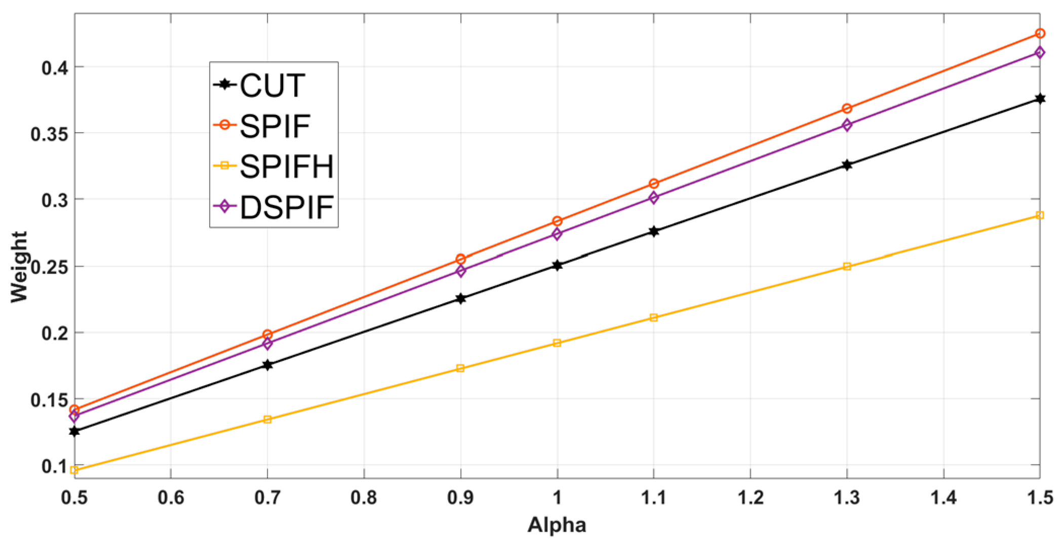
| Coefficient α/Preference Vector x | |||||||
|---|---|---|---|---|---|---|---|
| Strategy | 0.5 | 0.7 | 0.9 | 1.0 | 1.1 | 1.3 | 1.5 |
| CUT | 0.1253 | 0.1754 | 0.2255 | 0.2506 | 0.2757 | 0.3258 | 0.3759 |
| SPIF | 0.1417 | 0.1984 | 0.2551 | 0.2835 | 0.3118 | 0.3685 | 0.4252 |
| SPIFH | 0.0959 | 0.1343 | 0.1727 | 0.1919 | 0.2111 | 0.2495 | 0.2878 |
| DSPIF | 0.1370 | 0.1918 | 0.2466 | 0.2740 | 0.3014 | 0.3562 | 0.4110 |
| Alloy Element | Chemical Symbol | Mass Percentage (%) |
|---|---|---|
| Aluminum | Al | 5.5–6.75 |
| Vanadium | V | 3.5–4.5 |
| Carbon | C | 0.10 |
| Iron | Fe | 0.3 |
| Oxygen | O | 0.02 |
| Nitrogen | N | 0.05 |
| Hydrogen | H | 0.015 |
| Silicon | Si | 0.15 |
| Remainder | - | 0.4 |
| Characteristic | Measurement Unit | Value |
|---|---|---|
| Yield Strength | [MPa] | 965–1103 |
| Tensile Strength | [MPa] | 896–1034 |
| Density | [g/cm3] | 4.5 |
| Modulus of Elasticity (Young modulus) | [GPa] | 116 |
| No. | No. of Specimens/Set | Direction of Lamination (°) | Temperature (°C) |
|---|---|---|---|
| 1. | 3 | 90° | 25 °C |
| 2. | 3 | 0° | 25 °C |
| 3. | 3 | 45° | 25 °C |
| Characteristic | Measurement Unit | Value | ||
|---|---|---|---|---|
| Specimen Cutting Angle | [°] | 0 | 45 | 90 |
| The modulus of elasticity E | [MPa] | 49,645.24 | 49,779.71 | 52,587.8 |
| Flow Limit Rp0.2 | [MPa] | 881.9 | 863.11 | 922.51 |
| Tensile Strength Rm | [MPa] | 960.76 | 992.76 | 1001.35 |
| Coefficient of hardening n | [-] | 0.16 | 0.1 | 0.13 |
| Resistance coefficient K | [Pa] | 1618.9 | 1190.88 | 1392.81 |
| Elongation εmax | [%] | 5.5 | 7.8 | 6.4 |
| Trajectory Type | Geometrical Primitive | Code | Observations |
|---|---|---|---|
| Circular trajectories | Contour curve (circle) | CT | The lead-in/lead-out points are lying on the same line (cone generatrix) |
| Circular trajectories with special entry points | Contour curve (circle) | CTSEP | The lead-in/lead-out points are distributed on the part surface |
| Spiral trajectories | Spatial spiral | ST | Only one lead-in and one lead-out point |
| Crt. No. | Base Diameter d [mm] | Vertical Step p [mm] | Height h [mm] | Cone Angle α [°] | Punch Diameter dp [mm] | Trajectory Type |
|---|---|---|---|---|---|---|
| 1. | 55 | 0.4 | 12 | 30 | 8 | CT |
| 2. | 0.4 | 30 | 10 | CT | ||
| 3. | 0.6 | 30 | 8 | CT | ||
| 4. | 0.6 | 30 | 10 | CT | ||
| 5. | 0.2 | 35 | 8 | CT | ||
| 6. | 0.2 | 35 | 10 | CT | ||
| 7. | 0.4 | 35 | 8 | CTSEP | ||
| 8. | 0.4 | 35 | 10 | CTSEP | ||
| 9. | 0.6 | 35 | 8 | CTSEP | ||
| 10. | 0.6 | 35 | 10 | CTSEP | ||
| 11. | 0.2 | 36 | 8 | CT | ||
| 12. | 0.2 | 36 | 10 | CT | ||
| 13. | 0.4 | 36 | 8 | CTSEP | ||
| 14. | 0.4 | 36 | 10 | CTSEP | ||
| 15. | 0.6 | 36 | 8 | ST | ||
| 16. | 0.6 | 36 | 10 | CTSEP | ||
| 17. | 0.2 | 37 | 8 | CTSEP | ||
| 18. | 0.2 | 37 | 10 | CTSEP | ||
| 19. | 0.4 | 37 | 8 | ST | ||
| 20. | 0.4 | 37 | 10 | ST | ||
| 21. | 0.6 | 37 | 10 | ST | ||
| 22. | 0.2 | 38 | 8 | ST | ||
| 23. | 0.2 | 38 | 10 | ST | ||
| 24. | 0.4 | 38 | 10 | ST |
| Part No. | Characteristics | Measured Values |
|---|---|---|
| 1. | α° = 30/p = 0.4/dp = 8 mm/CT | α° = 31.485 Ra = 15.4 μm/Rz = 23.1 μm |
| 3. | α° = 30/p = 0.6 mm/dp = 8 mm/CT | α° = 31.125 Ra = 19 μm/Rz = 52.4 μm |
| 6. | α° = 35/p = 0.2 mm/dp = 10 mm/CT | α° = 36.125 Ra = 6 μm/Rz = 35.3 μm |
| 8. | α° = 35/p = 0.4 mm/dp = 10 mm/CTSEP | α° = 35.86 Ra = 16.5 μm/Rz = 58.2 μm |
| 11. | α° = 36/p = 0.2 mm/dp = 8 mm/CT | α° = 35.865 Ra = 10.3 μm/Rz = 37.5 μm |
| 18. | α° = 37/p = 0.2 mm/dp = 10 mm/CTSEP | α° = 38.8 Ra = 8.3 μm/Rz = 21 μm |
| 23. | α° = 38/p = 0.2 mm/dp = 10 mm/ST | α° = 38.56 Ra = 3.5 μm/Rz = 18.3 μm |
| 24. | α° = 38/p = 0.4 mm/dp = 10 mm/ST | α° = 38.77 Ra = 6.8 μm/Rz = 31.6 μm |
| Part d = 55 mm, α = 30°, p = 0.4 mm, dp = 10 mm, ST | Characteristic Input | |||||
|---|---|---|---|---|---|---|
| Major Strains ε1 | Minor Strains ε2 | Thickness Reduction smax | ||||
| % | log | % | log | % | log | |
| Experimental | 21.52 | 0.1951 | 4.78 | 0.0467 | 21.5 | 0.242 |
| Simulated | - | 0.2083 | - | 0.0123 | - | 0.216 |
| Cranioplasty Plate | Characteristic Input | ||
|---|---|---|---|
| Major Strains ε1 [%] | Minor strains ε2 [%] | Thickness Reduction smax [%] | |
| Characteristic | 14.5 | 4.3 | 17.44 |
© 2018 by the authors. Licensee MDPI, Basel, Switzerland. This article is an open access article distributed under the terms and conditions of the Creative Commons Attribution (CC BY) license (http://creativecommons.org/licenses/by/4.0/).
Share and Cite
Racz, S.G.; Breaz, R.E.; Tera, M.; Gîrjob, C.; Biriș, C.; Chicea, A.L.; Bologa, O. Incremental Forming of Titanium Ti6Al4V Alloy for Cranioplasty Plates—Decision-Making Process and Technological Approaches. Metals 2018, 8, 626. https://doi.org/10.3390/met8080626
Racz SG, Breaz RE, Tera M, Gîrjob C, Biriș C, Chicea AL, Bologa O. Incremental Forming of Titanium Ti6Al4V Alloy for Cranioplasty Plates—Decision-Making Process and Technological Approaches. Metals. 2018; 8(8):626. https://doi.org/10.3390/met8080626
Chicago/Turabian StyleRacz, Sever Gabriel, Radu Eugen Breaz, Melania Tera, Claudia Gîrjob, Cristina Biriș, Anca Lucia Chicea, and Octavian Bologa. 2018. "Incremental Forming of Titanium Ti6Al4V Alloy for Cranioplasty Plates—Decision-Making Process and Technological Approaches" Metals 8, no. 8: 626. https://doi.org/10.3390/met8080626