Article

Improvement in Thermomechanical Reliability of Low Cost Sn-Based BGA Interconnects by Cr Addition

1
Micro-Joining Center, Korea Institute of Industrial Technology, 156 Gaetbeol-ro, Yeonsu-gu, Incheon 22003, Korea
2
Graduate School of Engineering, Osaka University, 2-1 Yamadaoka, Suita, Osaka 565-0871, Japan
3
Joining and Welding Research Institute, Osaka University, 11-1 Mihogaoka, Ibaraki, Osaka 567-0047, Japan
*
Author to whom correspondence should be addressed.
Metals 2018, 8(8), 586; https://doi.org/10.3390/met8080586
Submission received: 11 July 2018 / Revised: 24 July 2018 / Accepted: 26 July 2018 / Published: 27 July 2018
(This article belongs to the Special Issue Intermetallic Alloys)

Abstract

:
The exemption of Pb-bearing automobile electronics in the End of Life Vehicle (ELV) directive has recently expired, bring an urgent need to find Pb-free alloys that can maintain good performance under high-temperature and vibration conditions for automobile application. In this study, a new lead-free solder, Sn-0.7Cu-0.2Cr (wt.%) alloy, was developed. To evaluate the thermomechanical reliability of the new solder alloy in automobile electronics, a thermal shock test was performed. The results show that the presence of Cr in solder inhibits the growth of interfacial Cu3Sn layer and the formation of Kirkendall voids, which effectively improves the joint reliability under intense thermal shock condition compared with the commercial SAC305 and SC07 solders. Specifically, the shear strength of the Sn-0.7Cu-0.2Cr/Cu solder joints was higher by 23% and 44% than that of SAC305 and SC07 solder joints after 2000 cycles of thermal shock at 1 m/s shear speed.

1. Introduction

Due to environmental concerns, legislation has come into effect, which was passed by the European Union in 2002, to ban the use of Pb and other toxic materials in electronic packaging [1,2]. Extensive searches for Pb-free solder alloys have been conducted over the past two decades. Nowadays, a Pb-free process has been successfully achieved in consumer electronics production, whereas Pb-bearing solders are still used in the vehicles industry because of the reliability and safety concerns of Pb-free solder alternatives [3,4]. However, this exemption ceases to exist with the release of the latest End of Life Vehicle (ELV) directive, in which some new restrictions explicitly demand that Pb-bearing solder cannot be used in automotive electronics after 1 January 2016 [5]. In this context, how to improve the lead-free solder reliability in the automotive electronics application has become a research hotspot.
Recently, SnAgCu (SAC) solders have been most widely used in automobile electronics [5]. In terms of wettability and operation temperature, the SAC solders perform well. However, due to numerous brittle Ag3Sn intermetallic compounds (IMC) existing in the matrix, the SAC solder exhibits poor drop reliability, which is a significant threat, because the joints are always subject to vibrations of 3 Grms to 20 Grms in actual operation conditions [6]. Additionally, cost is another important factor that limits the SAC solder application. It should be noted that Ag is a noble metal, whose price is approximately 30 times higher than that of Sn. A 1% reduction of Ag in a solder alloy results in at least a 15% reduction of the total solder cost. Currently, commercial imperatives to reduce costs have raised considerable interest in lowering the Ag content of SAC solder alloys to reduce the base alloy cost, especially in the context of decreasing profits in electronics manufacturing due to intense competition [7,8,9]. In this context, Ag-free solders, specifically the eutectic SC07 solder, has attracted much attention in automotive electronic applications because of the low cost and good drop reliability. Unfortunately, the drawback of Sn-Cu solder is also obvious. The IMC growth at the SnCu/Cu interface is much faster than that at the SAC/Cu interface. A too-thick IMC layer deteriorates the solder joint reliability because the IMC is brittle and possess lots of defects, such as Kirkendall voids inside [1,10]. Therefore, the prevention of excessive growth of IMC is of interest to materials researchers. Recently, several research groups have focused on developing composite electronic interconnect materials doped with metallic (e.g., Ni, Ag, Al, Co, Cr, etc.) [11,12,13,14,15,16,17] and ceramic (Al2O3, ZrO2, CeO2, etc.) [17,18,19] particles to control their interfacial microstructure and mechanical properties. For example, a trace amount of Cr in lead-free SnZn solder could repress the atomic diffusion and therefore reduce the interfacial IMC growth [15,16]. However, the effect of Cr addition in the SnCu/Cu system has not been systemically evaluated in the literature.
A novel Sn-0.7Cu-0.2Cr solder has been developed for automobile electronics applications [20]. In this study, to be better consistent with the practical application environment, the Sn-0.7Cu-0.2Cr solder was fabricated as BGA (ball grid array) solder balls and soldered on the prototype modules. After cycles of thermal shock testing, the microstructure evolution of the BGA solders was observed and the shear strength of the solder balls was measured. In addition, to evaluate the reliability of the Sn-0.7Cu-0.2Cr solder in the automobile electronics application, the microstructure and shear strength variation of the commercial SAC305 and SC07 solders under thermal shock conditions were evaluated for comparison.

2. Experimental Procedures

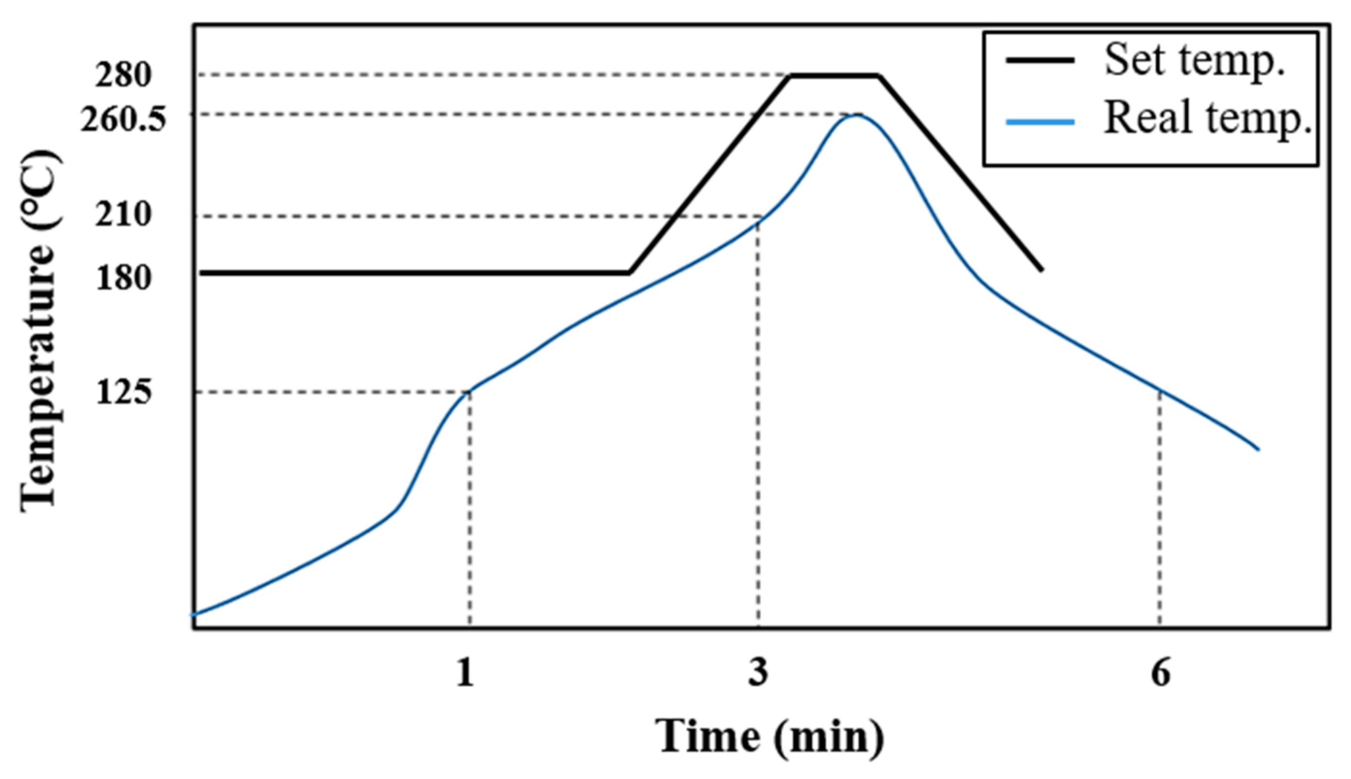
2.1. Preparation of Samples

SAC305, SC07 and SC-Cr alloys were prepared from pure (>99.99 wt.%) metals by using induction heating in a high-vacuum argon atmosphere at 1100 °C for 1 h. Then, solder balls with diameters of 300 μm were fabricated by using gas atomizing methods. Cu pads with an organic solderability preservative (OSP) surface finish on flame retardant (FR-4) boards was employed as solder wetting substrates. The OSP layer was 0.3 μm in thickness and the bottom Cu layer was 230 μm in diameter and 20 μm in thickness. For sample preparation, the solder balls were coated with some flux, placed on the Cu pad and then reflowed by using an 9-zone reflow machine (1809-EXL; Heller, Florham Park, NJ, USA). After reflow, the test samples were cooled to room temperature in air. Figure 1 shows the setting temperatures and the real reflow profile for the SC-Cr, which is obtained by a reflow profile checker installed in the reflow machine. The peak temperatures of the SAC305, SC07 and SC-Cr solders were 250, 255 and 260.5 °C, respectively. Table 1 listed the processing parameters. Some of the samples were tested in a VT 7006 chamber (Votsch, Berlin, Germany) for 500 to 2000 shocks at a cyclic temperature range of −45–+125 °C, with each shock lasting 20 min (JESD22-104; JEDEC, Arlington, VA, USA).
After soldering and thermal shock testing, the samples were mounted in epoxy and polished to reveal the interfaces and internal microstructures. The samples were then etched with 3 vol.% HNO3 and 2 vol.% HCl (in ethanol) solution for a few seconds to reveal the cross-sectional microstructures.

2.2. Characterization of the Solder/Cu Microstructure

Scanning electron microscopy (SEM; S-4700, Hitachi, Tokyo, Japan), together with energy dispersive X-ray spectroscopy (EDX; EDAX Genesis XM2 60, AMETEK, Mahwah, NJ, USA), was employed to characterize the IMC microstructure. For kinetic studies, the IMC thicknesses were measured from the SEM images of the metallographic cross-sections using the following image analysis procedure [7,8]: (1) an SEM image of each sample was obtained at the appropriate magnification; (2) the grayscale SEM image was enhanced using Adobe Photoshop (CS6, Adobe systems, San Jose, CA, USA, 2017) to identify the interfaces between the different layers; and (3) the mean thickness (HIMC) of individual layers was calculated using the following equation:
HIMC = HSEM × NIMC/NSEM
where HSEM is the actual height of the SEM image, and NIMC and NSEM are the numbers of pixels in the IMC layers and the entire image, respectively.

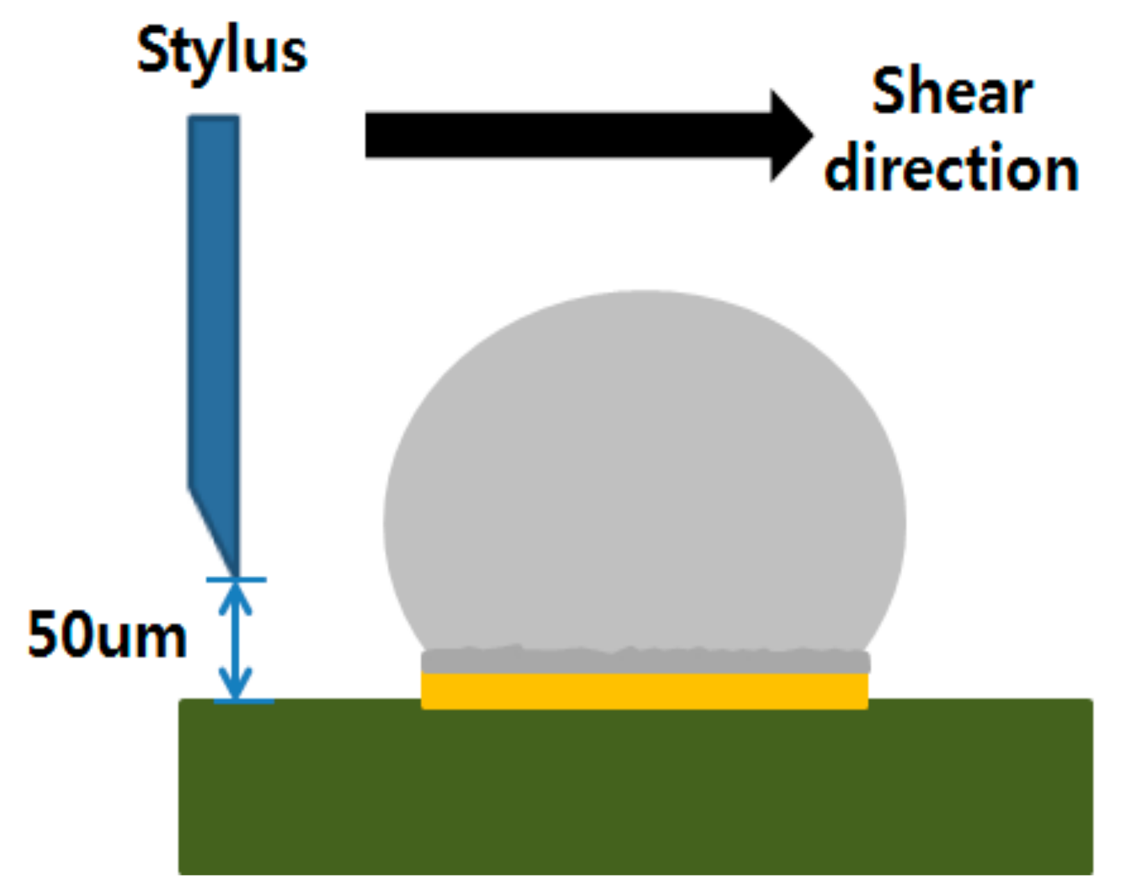
2.3. Mechanical Tests

To evaluate the mechanical properties of solder joints after thermal shocks, ball shear tests were conducted at shear heights of 50 μm with shear speed of 0.0002 m/s, 0.01 m/s, 0.1 m/s and 1 m/s using a bonding tester (PTR-1101, Rhesca Co., Tokyo, Japan), as shown in Figure 2. The shear force value was estimated by averaging 20 solder balls. After shear testing, all the fracture surfaces were observed in top and cross-section views using SEM.

3. Results and Discussion

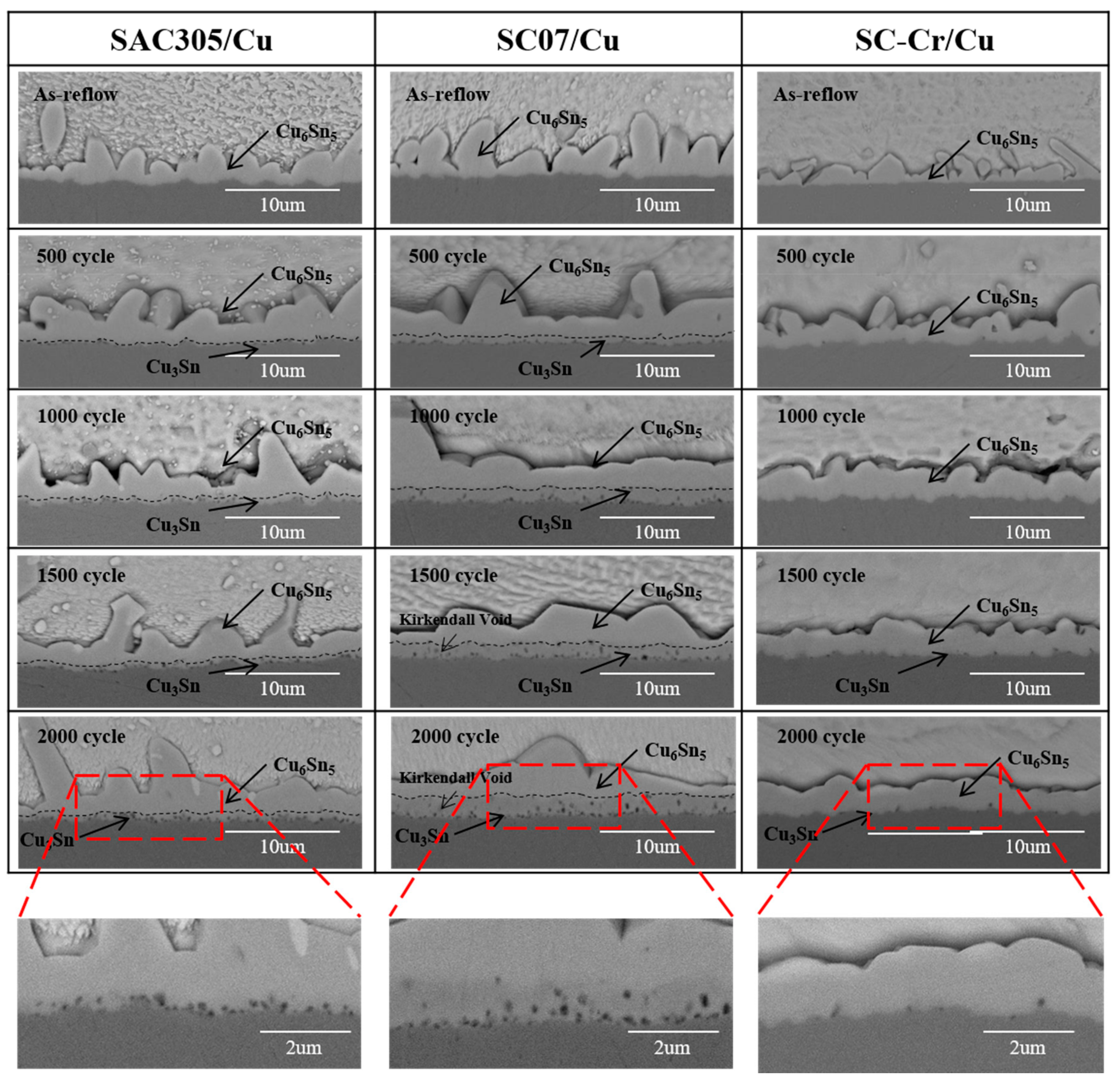
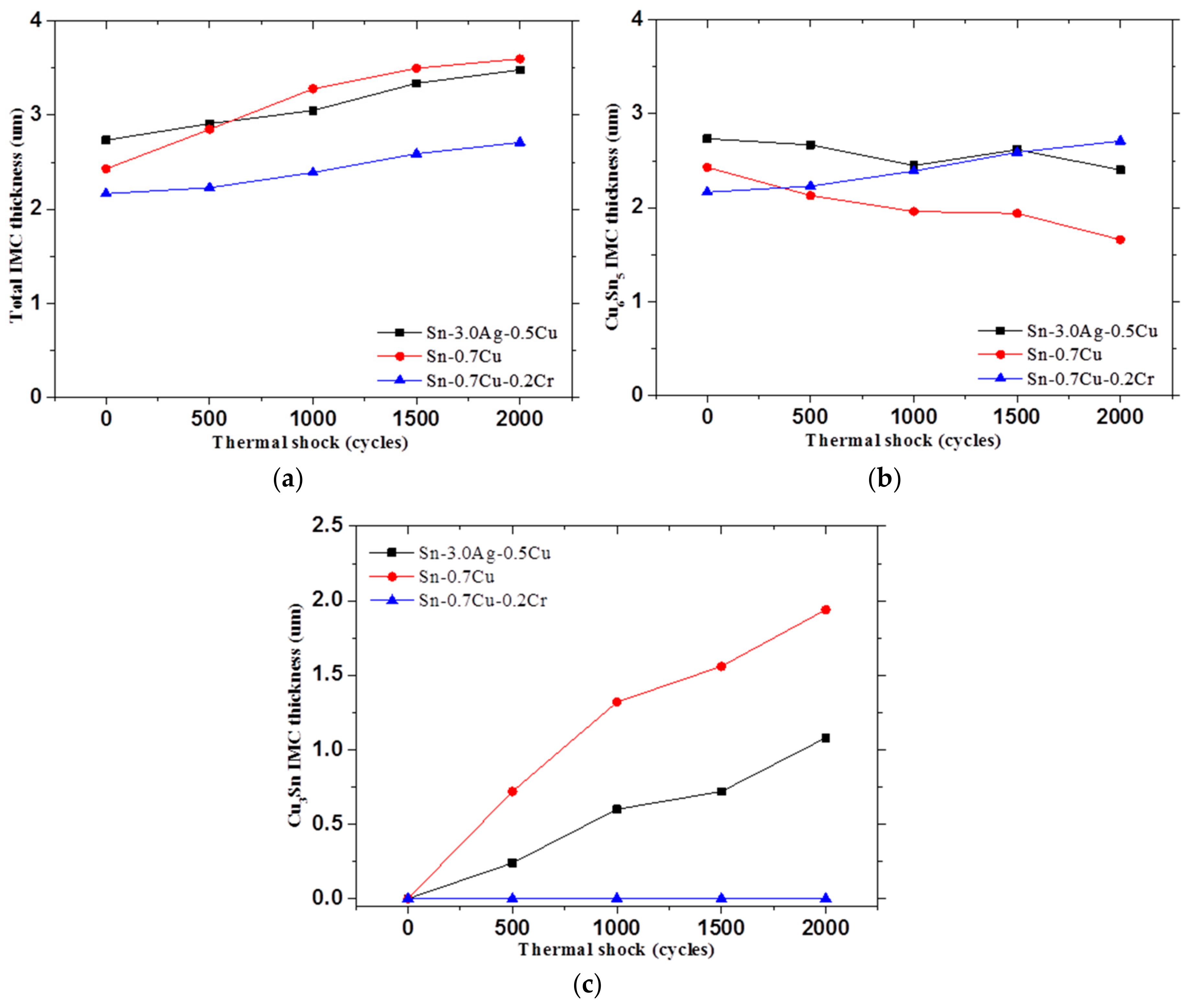
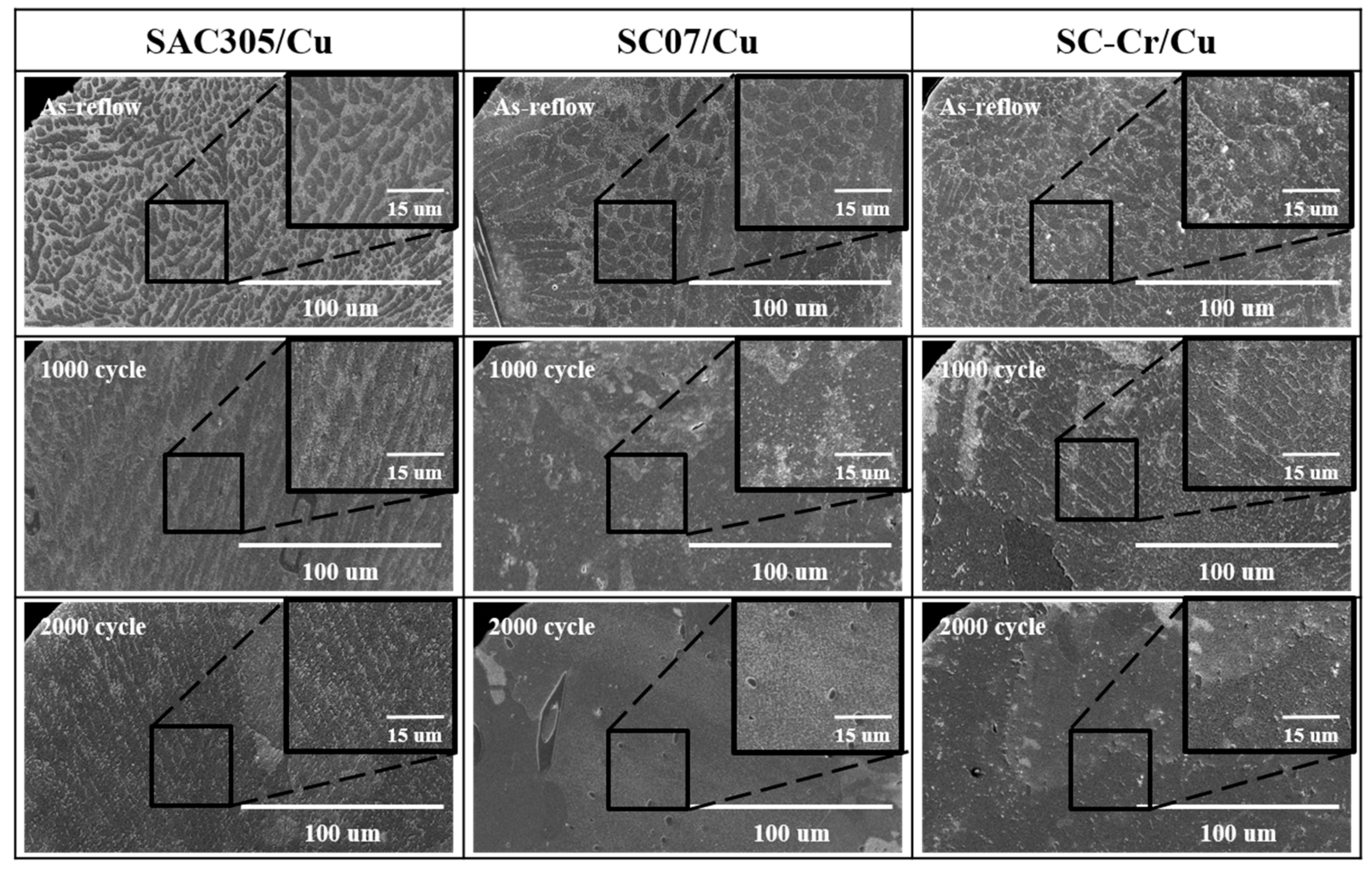
3.1. Interfacial Microstructure

Figure 3 shows the cross-sectional microstructures of the IMC layers formed at SAC305/Cu, SC07/Cu and SC-Cr/Cu interfaces during thermal shock testing. Generally, the interfacial IMC became thicker and flatter with increasing thermal shocks. Compared with the interfacial IMC formed in the three reaction systems, the addition of Cr effectively inhibited interfacial IMC growth, especially the Cu3Sn IMC growth. Specifically, very few Cu3Sn IMC and Kirkendall voids were detected at the SC-Cr/Cu interface, even after 2000 cycles of thermal shock testing, whereas the Cu3Sn and Kirkendall voids were significant at the SAC305/Cu and SC07/Cu interfaces after 1000 cycles. To quantify the difference, the thicknesses of the IMC layers formed in the three reaction systems were measured using imaging analysis methods. Compared with the results plotted in Figure 4, Cr inhibited the interfacial IMC growth primarily by slowing down the Cu3Sn growth.
Fundamentally, the formation and growth of the interfacial IMC growth is caused by the Cu and Sn diffusion through the interface. To figure out how Cr inhibits the interfacial IMC growth, its effects on the Cu and Sn diffusion must be clarified. Next, the amounts of Cu and Sn atoms in the interfacial IMC layers were separately calculated for comparison as follows [21,22]:
M Cu = T Cu 6 Sn 5 · ρ Cu 6 Sn 5 · υ Cu / Cu 6 Sn 5 + T Cu 3 Sn · ρ Cu 3 Sn · υ Cu / Cu 3 Sn
M Sn = T Cu 6 Sn 5 · ρ Cu 6 Sn 5 · υ Sn / Cu 6 Sn 5 + T Cu 3 Sn · ρ Cu 3 Sn · υ Sn / Cu 3 Sn
where M is the total weight of the Cu or Sn element per unit area, T is the thickness of the Cu6Sn5 or Cu3Sn layers, ν is the weight fraction of Cu or Sn in the Cu6Sn5 or Cu3Sn molecule and ρ is the density of the Cu6Sn5 or Cu3Sn IMC, which is 8.45 or 8.97 g·cm3, respectively [23,24]. The diffusion rates of Sn and Cu were listed in Figure 5. The Sn diffusion rate are 0.38, 0.14 and 1.49 μg·mm−2/K·cycles in SAC305/Cu, SC07/Cu and SC-Cr/Cu reactions, respectively. Correspondingly, the Cu diffusion rates are 3.13, 5.36 and 0.96 μg·mm−2/K·cycles in SAC305/Cu, SC/Cu and SC-Cr/Cu reaction systems, respectively. The addition of Cr slightly increased Sn diffusion but significantly repressed the Cu diffusion under thermal shock test. From these results, we believe that Cr inhibited the solid-state interfacial IMC growth primarily through slowing down the Cu diffusion through the interface, although the root mechanism is still unclear. It is well known that only the Cu3Sn and Cu6Sn5 phases are formed at the SAC/Cu interface. Therefore, under similar Sn diffusion conditions, a lower Cu diffusion flux leads to repression of the Cu3Sn layer growth and the Kirkendall void formation at the interface in the SC-Cr/Cu reaction system, as shown in Figure 3.
Generally, many Kirkendall voids would be formed in the interfacial IMC layers, especially in the Cu3Sn layer, with prolonged thermal treatment, as shown in Figure 3. This is because Cu is the dominant diffusing species in the reaction and the competition in growth between Cu6Sn5 and Cu3Sn tends to favor the latter when the ratio of Cu to Sn is large in the sample [1]. The transformation of 1 molecule of Cu6Sn5 into 2 molecules of Cu3Sn will leave behind 3 Sn atoms, which will attract 9 atoms of Cu to form 3 more molecules of Cu3Sn. The vacancy flux needed to transport the Cu atoms will accumulate at the Cu/Cu3Sn interface to form Kirkendall voids, which are undesirable in device applications [1]. Combined with the brittle nature of the IMC, such void defects could further deteriorate the interfacial connection of the solder joint under mechanical stress. Therefore, the inhibition of interfacial IMC growth and the Kirkendall formation in the SC-Cr/Cu reaction system is expected to improve the joint reliability, which will be discussed in the following section.

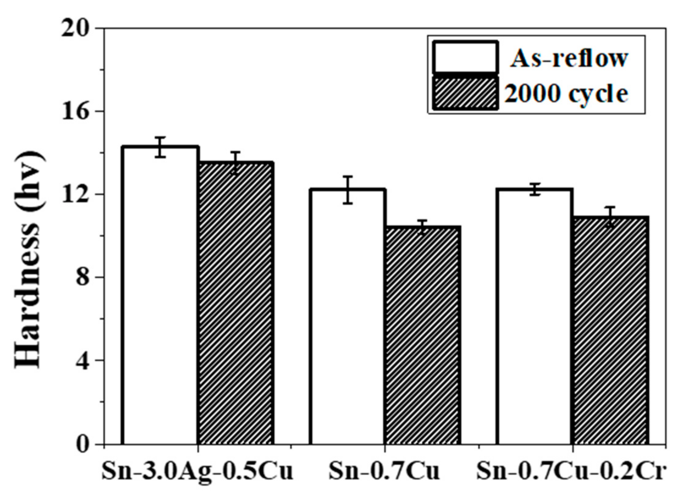
3.2. Mechanical Reliability

The shear strength of the solder joints depends on the microstructure of the solder matrix and the interfacial connection. According to Kim’s simulation results of shear tests at different shear speeds [25,26], the shear force increased with increasing shear speed. At a low shear speed, the stress could be released though the deformation of the soft solder matrix, indicating that the joint strength should be more closely related to the strength of solder matrix; whereas at a high shear speed, due to the rapid deformation in solder matrix, a great stress would accumulate at the interface, indicating that the shear strength should be more related to the interfacial connection. Therefore, shear testing at shear speeds from 0.01 m/s to 1 m/s was conducted to examine the effects of solder microstructure and the interfacial IMC on the joint reliability.
Figure 6 shows the variation of the solder joint strength with prolonged thermal shock test at various shear speeds. Generally, the shear strength of the solder joints decreased with thermal shock test. These results are consistent with Kim’s simulation [25,26] and Gain’s experiments [27,28]. Although the trends in shear strength with thermal shock testing were similar, significant differences were observed in terms of shear speeds: at a low shear speed (0.01 m/s), the SAC305/Cu solder joints exhibited highest strength, whereas SC-Cr/Cu solder joints show highest strength when the shear speed exceeds 0.1 m/s. As mentioned above, the difference should derive from the different fracture mechanisms under various shear speeds. To confirm this assumption, the fracture morphology of these solder joints was observed and classified, as shown in Figure 7 and Figure 8. All the fractures exhibited ductile fracture morphology at a low shear speed, whereas the brittle fracture becomes dominant when the shear speed exceeds 0.1 m/s. The results indicate that the joint strength is determined by the solder matrix strength in the case of a low shear speed and more relies on the interfacial connection in the case of a high shear speed.
After solidification, the solder matrix is composed of β-Sn dendrites, eutectic areas, and some large precipitated IMC [21,22]. During soldering, Cu and Ag are dissolved in solder matrix, and due to the great difference in solubility, they precipitate during cooling in the form of Ag3Sn and Cu6Sn5 IMC, dispersing in solder matrix to form eutectic areas, as shown in Figure 9. Because these IMC is much harder than the solder matrix, these dispersed IMC could act as second-phase particles to pin the dislocation and block the crack propagation generated in shear test process, therefore enhancing the joint strength. It is known that more IMC exist in SAC305 solder than that in SC07 and SC-Cr solders. Correspondingly, the SAC305 solder exhibited higher hardness and strength than the other two solders (Figure 6 and Figure 10) in the case of a low shear speed. With prolonged thermal shock, the solder microstructure coarsened, meaning that the strengthening effect caused by second-phase particles and grain boundaries gradually weakened. Therefore, the joint strength decreased with prolong thermal shock test.
In the case of a high shear speed, a great stress generated in the solder matrix due to the rapid and great deformation and spread to the interfacial area during shear test. Because of the brittle property, the interfacial IMC is prone to crack under such intense stress. Generally, thicker interfacial IMC layers with more defects inside are more likely to crack. As shown in Figure 3 and Figure 4, the interfacial IMC became thicker with prolonged thermal shock times, causing a decrease in shear strength. Compared with the SAC305/Cu and SC07/Cu solder joints, the addition of Cr effectively inhibit interfacial IMC growth and Kirkendall void formation. Therefore, the strength of SC-Cr/Cu solder joints is much higher than the other two solder joints at a high-speed shear test. Specifically, the shear strength of the SC-Cr/Cu solder joints increased by 23% and 44% compared to that of SAC305 and SC07 solder joints after 2000 cycles of thermal shock at a shear speed of 1 m/s. Since the high-speed shear test could well reflect the mechanical reliability of BGA solder joints under dynamic loading [26], it is reasonable to expect that the SC-Cr solder joints could well perform under vibration condition in automotive applications.

4. Conclusions

In this study, the interfacial microstructure evolution and shear strength of Sn-0.7Cu-0.2Cr solder joints under intense thermal shock condition were investigated. The results are summarized as follows:
(1)
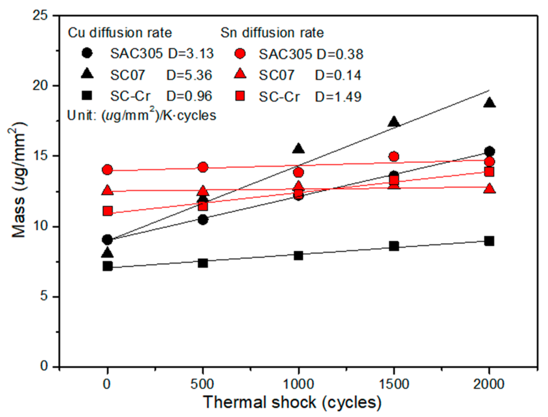
The addition of Cr effectively slowed down the growth rate of the interfacial IMC layer during thermal shock compared with the Sn-0.7Cu solder.
(2)
During thermal shock, the Cr in solder inhibits the growth of interfacial IMC layer and the formation of Kirkendall voids by slowing down the Cu diffusion at the interface.
(3)
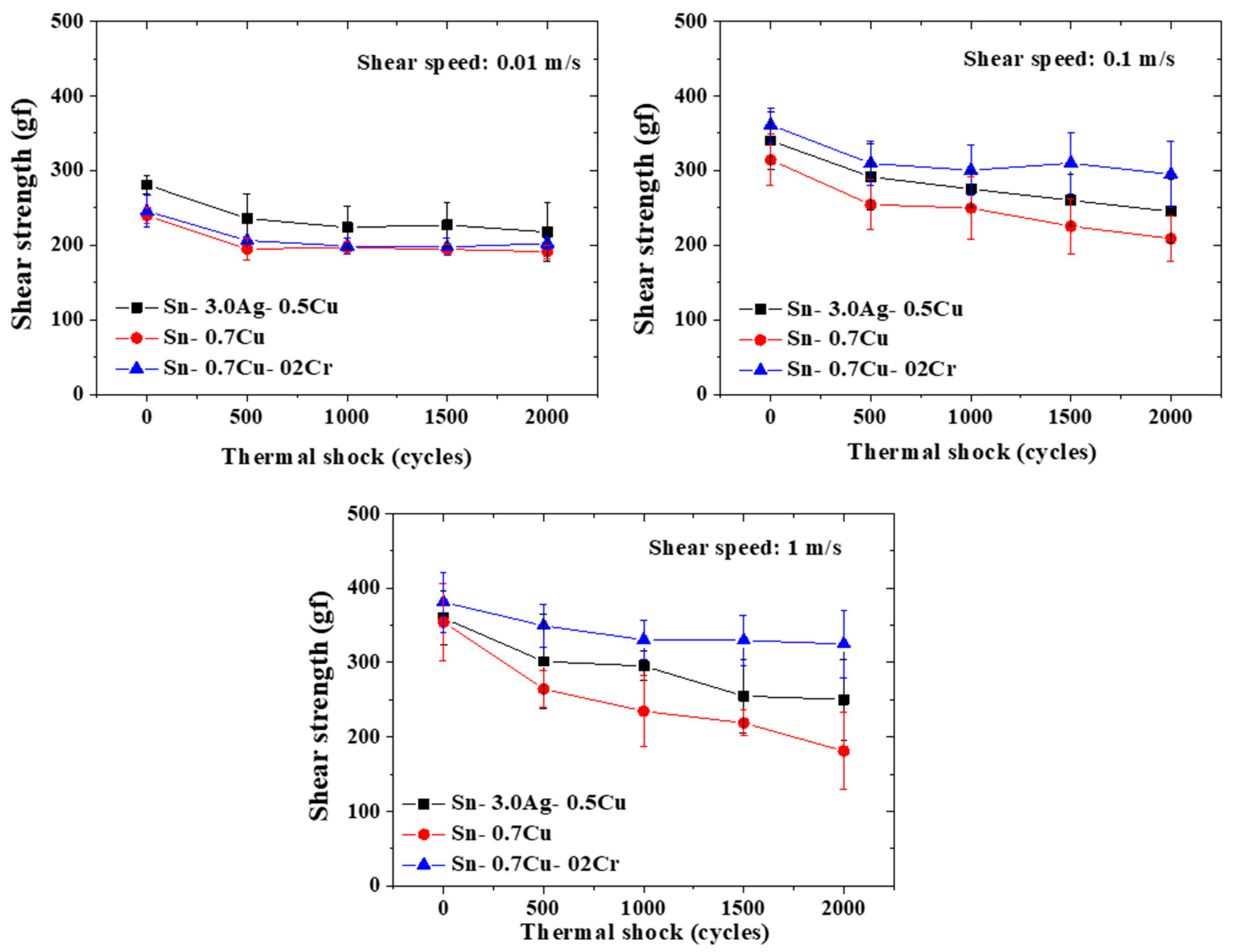
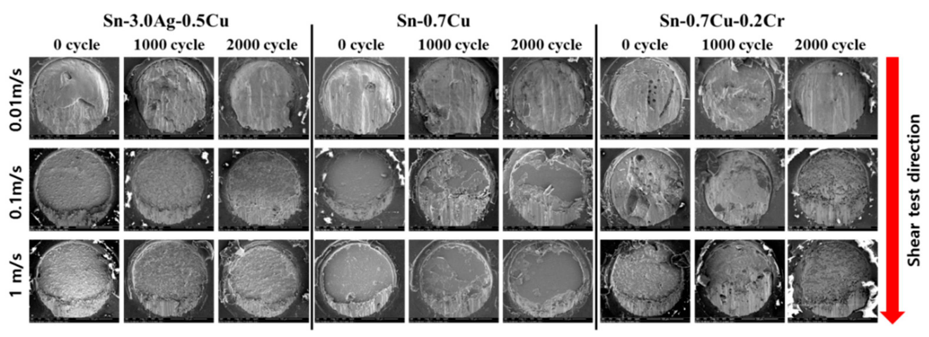
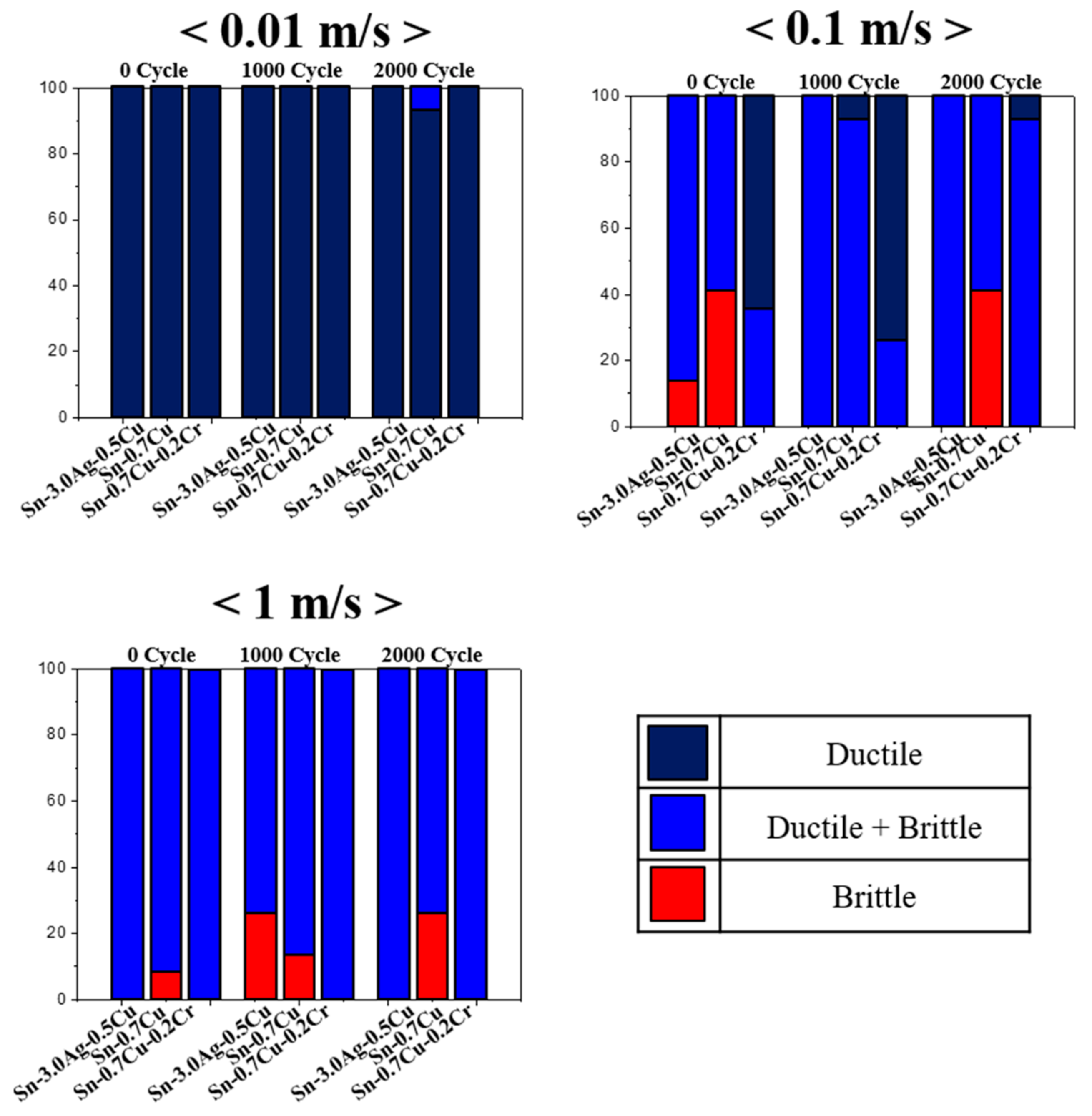
The shear strength of the solder joints decreased with thermal shock testing. The solder fracture is dominated by ductile fracture at a low shear speed, whereas it exhibited a more brittle type at a high shear speed.
(4)
The reduced interfacial IMC thickness and Kirkendall voids in SC-Cr/Cu solder joints effectively improves the joint reliability under intense thermal shock conditions compared with the commercial SAC305/Cu and SC07/Cu solders. Specifically, the shear strength of the SC-Cr/Cu solder joints were much higher than that of SAC305 and SC07 solder joints after 2000 cycles of thermal shock at shear speed of 1 m/s.

Author Contributions

J.B., C.-W.L. conceived and designed the experiments; D.-Y.Y. performed the experiments; Y.-H.K., J.-W.Y. and M.Y. analyzed the data; J.B. and H.N. wrote the paper and edited.

Funding

This research was funded by Ministry of Commerce Industry and Energy in Korea government (Grant No. 10077336).

Conflicts of Interest

The authors declare no conflict of interest.

References

  1. Tu, K.N. (Ed.) Solder Joint Technology: Materials, Properties, and Reliability; Springer: New York, NY, USA, 2007. [Google Scholar]
  2. Zeng, K.; Tu, K.N. Six cases of reliability study of Pb-free solder joints in electronic packaging technology. Mater. Sci. Eng. R Rep. 2005, 38, 55–105. [Google Scholar] [CrossRef]
  3. Zhang, Q.K.; Long, W.M.; Zhang, Z.F. Growth behavior of intermetallic compounds at Sn–Ag/Cu joint interfaces revealed by 3D imaging. J. Alloys Compd. 2015, 646, 405–411. [Google Scholar] [CrossRef]
  4. Hurtony, T.; Almasy, A.S.L.; Len, A.; Kugler, S.; Bonyar, A.; Gordon, P. Characterization of the microstructure of tin-silver lead free solder. J. Alloys Compd. 2016, 672, 13–19. [Google Scholar] [CrossRef] [Green Version]
  5. Hong, W.S.; Oh, C.; Kim, M.S.; Lee, Y.W.; Kim, H.J.; Hong, S.J.; Moon, J.T. Al and Si alloying effect on solder joint reliability in Sn-0.5Cu for automotive electronics. J. Electron. Mater. 2016, 45, 6150–6162. [Google Scholar]
  6. Johnson, R.W.; Evans, J.L.; Jacobsen, P.; Thompson, J.R.; Christopher, M. The changing automotive environment: high-temperature electronics. IEEE Trans. Electron. Pack. Manuf. 2004, 27, 164–176. [Google Scholar] [CrossRef]
  7. Yang, M.; Ji, H.; Wang, S.; Ko, Y.-H.; Lee, C.-W.; Wu, J.; Li, M. Effects of Ag content on the interfacial reactions between liquid Sn–Ag–Cu solders and Cu substrates during soldering. J. Alloys Compd. 2016, 679, 18–25. [Google Scholar] [CrossRef]
  8. Ko, H.; Lee, J.D.; Yoon, T.; Lee, C.W.; Kim, T.S. Controlling interfacial reactions and intermetallic compound growth at the interface of a lead-free solder joint with layer-by-layer transferred grapheme. ACS Appl. Mater. Interfaces 2016, 8, 5679–5686. [Google Scholar] [CrossRef] [PubMed]
  9. Zhang, S.; Yang, M.; Jin, M.; Huang, W.; Lin, T.; Peng, H.; Lin, P.; Paik, K.W. Mechanism of solder joint cracks in anisotropic conductive films bonding and solutions: Delaying hot-bar lift-up time and adding silica fillers. Metals 2018, 8, 42. [Google Scholar] [CrossRef]
  10. Kim, J.Y.; Yu, J.; Kim, S.H. Effects of sulfide-forming element additions on the Kirkendall void formation and drop impact reliability of Cu/Sn–3.5Ag solder joints. Acta Mater. 2009, 57, 5001–5012. [Google Scholar] [CrossRef]
  11. Gain, A.K.; Zhang, L. Microstructure, thermal analysis and damping properties of Ag and Ni nano-particles doped Sn–8Zn–3Bi solder on OSP-Cu substrate. J. Alloys Compd. 2014, 617, 779–786. [Google Scholar] [CrossRef]
  12. Zhang, S.; Yang, M.; Wu, Y.; Du, J.; Lin, T.; Peng, H.; Huang, M.; Paik, K.W. A study on the optimization of anisotropic conductive films for Sn-3Ag-0.5Cu-Based flex-on-board application at a 250 °C bonding temperature. IEEE Trans. Comp. Pack. Manuf. 2018, 8, 1–9. [Google Scholar] [CrossRef]
  13. Fouzder, T.; Li, Q.; Chan, Y.; Chan, D. Interfacial microstructure and hardness of nickel (Ni) nanoparticle-doped tin-silver-copper (Sn-Ag-Cu) solders on immersion silver (Ag)-plated copper (Cu) substrates. J. Mater. Sci. Mater. Electron. 2014, 25, 4012–4023. [Google Scholar] [CrossRef]
  14. Chen, X.; Zhou, J.; Xue, F.; Bai, J.; Yao, Y. Microstructures and mechanical properties of Sn-0.1Ag-0.7Cu-(Co, Ni, and Nd) lead-free solders. J. Electron. Mater. 2015, 44, 725–732. [Google Scholar] [CrossRef]
  15. Chen, X.; Hu, A.; Li, M.; Mao, D. Effect of a trace of Cr on intermetallic compound layer for tin–zinc lead-free solder joint during aging. J. Alloys Compd. 2009, 470, 429–433. [Google Scholar] [CrossRef]
  16. Bi, J.; Hu, A.; Hu, J.; Luo, T.; Li, M.; Mao, D. Effect of Cr additions on interfacial reaction between the Sn–Zn–Bi solder and Cu/electroplated Ni substrates. Microelectron. Reliab. 2011, 51, 636–641. [Google Scholar] [CrossRef]
  17. Zhang, L.; Tu, K.N. Structure and properties of lead-free solders bearing micro and nano particles. Mater. Sci. Eng. R Rep. 2014, 82, 1–32. [Google Scholar] [CrossRef]
  18. Yakymovych, A.; Plevachuk, Y.; Švec, P., Sr.; Švec, P.; Janičkovič, D.; Šebo, P.; Janičkovič, D.; Šebo, P.; Beronská, N.; Roshanghias, A.; et al. Morphology and shear strength of lead-free solder joints with Sn3.0Ag0.5Cu solder paste reinforced with ceramic nanoparticles. J. Electron. Mater. 2016, 45, 6143–6149. [Google Scholar] [CrossRef]
  19. Xing, W.Q.; Yu, X.Y.; Li, H.; Ma, L.; Zuo, W.; Dong, P.; Wang, W.X.; Ding, M. Effect of nano Al2O3 additions on the interfacial behavior and mechanical properties of eutectic Sn-9Zn solder on low temperature wetting and soldering of 6061 aluminum alloys. J. Alloys Compd. 2017, 695, 574–582. [Google Scholar] [CrossRef]
  20. Bang, J.; Yu, D.-Y.; Ko, Y.-H.; Kim, M.-S.; Nishikawa, H.; Lee, C.-W. Intermetallic compound formation and mechanical property of Sn-Cu-xCr/Cu lead-free solder joint. J. Alloys Compd. 2017, 728, 992–1001. [Google Scholar] [CrossRef]
  21. Yang, M.; Cao, Y.; Joo, S.; Chen, H.; Ma, X.; Li, M. Cu6Sn5 precipitation during Sn-based solder/Cu joint solidification and its effects on the growth of interfacial intermetallic compounds. J. Alloys Compd. 2014, 582, 688–695. [Google Scholar] [CrossRef]
  22. Yang, M.; Ko, Y.-H.; Bang, J.; Kim, T.-S.; Lee, C.-W.; Li, M. Effects of Ag addition on solid-state interfacial reactions between Sn–Ag–Cu solder and Cu substrate. Mater. Charact. 2017, 124, 250–259. [Google Scholar] [CrossRef]
  23. Ghosh, G.; Asta, M. Phase stability, phase transformations, and elastic properties of Cu6Sn5: Ab initio calculations and experimental results. J. Mater. Res. 2005, 20, 3102–3117. [Google Scholar] [CrossRef]
  24. Nogita, K.; Gourlay, C.M.; Nishimura, T. Cracking and phase stability in reaction layers between Sn-Cu-Ni solders and Cu substrates. JOM 2009, 61, 45–51. [Google Scholar] [CrossRef]
  25. Kim, J.W.; Kim, D.G.; Jung, S.B. Mechanical strength test method for solder ball joint in BGA package. Met. Mater. Int. 2005, 11, 121–129. [Google Scholar] [CrossRef]
  26. Kim, J.W.; Jang, J.K.; Ha, S.O.; Ha, S.S.; Kim, D.G.; Jung, S.B. Effect of high-speed loading conditions on the fracture mode of the BGA solder joint. Microelectron. Reliab. 2008, 48, 1882–1889. [Google Scholar] [CrossRef]
  27. Gain, A.K.; Zhang, L. Harsh service environment effects on the microstructure and mechanical properties of Sn-Ag-Cu-1 wt % nano-Al solder alloy. J. Mater. Sci. Mater. Electron. 2016, 27, 11273–11283. [Google Scholar] [CrossRef]
  28. Gain, A.K.; Zhang, L.; Quadir, M.Z. Thermal aging effects on microstructures and mechanical properties of an environmentally friendly eutectic tin-copper solder alloy. Mater. Des. 2016, 110, 275–283. [Google Scholar] [CrossRef]
Figure 1. Reflow profile for SC-Cr/Cu solder joints.
Metals 08 00586 g001
Figure 2. Schematic illustration of solder ball shear test.
Metals 08 00586 g002
Figure 3. Representative SEM images showing the interfacial microstructures of the solder joints after various cycles of thermal shock.
Metals 08 00586 g003
Figure 4. Plot of the thickness of IMC versus thermal shock cycles: (a) Total IMC thickness, (b) Cu6Sn5 IMC thickness, (c) Cu3Sn IMC thickness.
Metals 08 00586 g004
Figure 5. Plot of diffusivities of Cu and Sn versus thermal shock cycles.
Metals 08 00586 g005
Figure 6. Shear strength of solder joints under various shear speeds.
Metals 08 00586 g006
Figure 7. Fracture surfaces of the solder joints under various shear speeds.
Metals 08 00586 g007
Figure 8. Statistics of fracture mode of solder joins under various shear speeds.
Metals 08 00586 g008
Figure 9. Microstructures of solder ball under various thermal shock cycles.
Metals 08 00586 g009
Figure 10. Hardness of different solders.
Metals 08 00586 g010
Table 1. Reflow conditions.
SolderPre-Heating
Time (s)
Duration Time above
Melting Temperature (s)
Peak Reflow Temperature (°C)
Sn-3.0Ag-0.5Cu10753250
Sn-0.7Cu7347255
Sn-0.7Cu-0.2Cr7347260.5

