Article

Thermal Stability of Ultrafine Grained Pure Copper Prepared by Large Strain Extrusion Machining

1
School of Mechanical and Automotive Engineering, South China University of Technology, Guangzhou 510641, China
2
School of Mechanical Engineering, Hubei University of Technology, Wuhan 430068, China
*
Author to whom correspondence should be addressed.
Metals 2018, 8(6), 381; https://doi.org/10.3390/met8060381
Submission received: 16 April 2018 / Revised: 22 May 2018 / Accepted: 23 May 2018 / Published: 25 May 2018

Abstract

:
Ultrafine grained (UFG) pure copper chips with improved material strength have been successfully prepared by large strain extrusion machining (LSEM). However, the thermal stability of the UFG chips has been a key characteristic that has restricted their use in practical applications. To understand the influence of annealing temperature and annealing time on their microstructures and mechanical properties, the UFG chips were subjected to isochronous and isothermal annealing treatments as well as Vickers hardness tests in the present study. From the results, we found that the UFG chips maintain high hardness when annealing at temperatures up to 160 °C but begin to exhibit a reduction in their hardness while the annealing temperature reached above 200 °C. When annealed at 280 °C for 10–240 min, the grain size increased slightly and reached a stable value of 2 µm with an increase in annealing time and with a decrease in the hardness of the chips. These results indicated that UFG pure copper chips have good thermal stability at temperatures below 160 °C.

1. Introduction

Compared with traditional coarse polycrystalline materials, ultrafine grained (UFG) materials and nanocrystalline materials (NCMs) exhibit better physical, mechanical, and chemical properties due to their high density of defects and large volume percentage of grain boundary [1,2]. Hence, their preparation methods have become a hot topic in various fields. Among these methods, severe plastic deformation (SPD) has been increasingly valued by researchers, who have developed a variety of SPD processes [3]. The most commonly used processing methods include twist extrusion (TE) [4], high pressure torsion (HPT) [5], accumulative roll bonding (ARB) [6,7], and equal channel angular pressing (ECAP) [8,9].
With further progression of research, machining has been used to prepare NCMs and UFG materials, with this method being suitable for producing nanocrystalline chips of strong alloys and metals [10,11]. However, the obtained chips all had different sizes and extremely irregular shapes, which made it difficult to subsequently process and use these chips. On the basis of retaining and even enhancing the ability of severe plastic deformation in traditional cutting, a potential process, namely, large strain extrusion machining (LSEM), was proposed for the preparation of NCMs and UFG materials by Iglesias [12,13] and Moscoso [14], who learned from Cliffre’s “extrusion cutting” idea [15,16]. The working principle of LSEM is shown in Figure 1.
As shown in Figure 1, the LSEM tool consists of a cutting tool and a constraining tool. The cutting tool mainly carries out the cutting work and exerts the process of severe plastic deformation on the chips by the shearing and friction of the rake face. The constraining tool mainly controls the shape of chips and can enhance plastic deformation during LSEM through increasing the friction on the top of the chips. The shear strain ε can be estimated using the following equation:
ε = λ cos α + 1 λ cos α 2 tan α ,
where α is the tool rake angle and λ is the chip compression ratio. The chip compression ratio λ is used to control the strain and the geometry of the chips. Furthermore, this ratio can be varied by changing the chip thickness t c and the undeformed chip thickness t 0 , which can be determined using the following equation:
λ =   t c t 0 .
Iglesias et al. [12] studied the friction and wear properties of copper chips prepared by pure oxygen-free high conductivity (OFHC) and pure titanium chips prepared by LSEM. Later, Iglesias et al. [13] further studied the influence of the LSEM process parameters on the wear property of the materials. Sevier et al. [17] used ABAQUS finite element software to analyze the effects of the compression ratio, friction coefficient on strain, strain rate, and cutting force for different materials. Guo et al. [18] used a high-speed camera and particle image velocity software to study the variation law of the deformation zone in the LSEM process, while Cai et al. [19] studied the deformation field with high-speed imaging and digital image correlation (DIC). However, the limited sizes of NCMs that can be produced by machining and LSEM render them unsuitable for manufacturing structural components and mechanical parts. The possibility of creating large dimensional NCMs through the self-consolidation of UFG chips or their combination with other materials can possibly eliminate this limitation.
There are two possible ways of producing large dimensional NCMs and extending them to the application of UFG chips. One involves pulverizing the UFG chips through powder metallurgy methods under appropriate temperatures in order to squeeze them into large rod shapes. The other involves producing a high-performance composite by adding the UFG chips to low melting point metals, plastics, or high molecular polymers. In both methods, the UFG chips must be subjected to heat treatment. Furthermore, the materials are often in an environment with high temperatures in practice, which can cause a loss of their excellent properties. Therefore, it is important to study the thermodynamic behavior of the chips prepared by LSEM. In the study of thermal stability in LSEM, the annealing treatments of aluminum 6061 alloy and AISI1020 LSEM chips were carried out in a wide temperature range [20,21], while the performance and microstructure of the alloys were observed before and after annealing. However, there is still a lack of systematic research that focuses on copper, which is widely used in industries and daily life due to its excellent electrical conductivity, thermal conductivity, and chemical stability. In recent years, the thermal stability of materials prepared by different methods have been studied [22,23,24,25,26]. Gubicza et al. [22] analyzed Cu samples that were processed by 15 passes of TE, 20 cycles of multi-directional forging (MDF), 25 passes of ECAP, and 25 revolutions of HPT at room temperature, before studying the thermal stability of these samples at room and high temperatures. They found that the microstructures produced by MDF or TE were more stable than those obtained by ECAP or HPT. Abib et al. [24] investigated the thermal stability of a Cu-Cr-Zr alloy processed by ECAP pressing for up to 16 passes using isochronal annealing treatments from 250 to 850 °C for 1 h and found that the recrystallized grain size was stable between 250 °C and 500 °C, before increasing quickly with an achieved mean grain size of around 5.5 μm. Čížek et al. [25] prepared UFG copper by HPT and studied its thermal stability through positron lifetime spectroscopy. They found that the microstructure had no significant change when the temperature was below 150 °C, while abnormal grain growth took place as the temperature increased to 150 °C.
In this present work, the thermal stability of the UFG chips prepared by LSEM was experimentally analyzed, while the microstructure evolution was characterized by electron backscattered diffraction (EBSD). This study is designed to enrich the research on the thermodynamic behavior of UFG materials prepared by LSEM, to clarify the application range, and to promote further studies on LSEM.

2. Materials and Methods

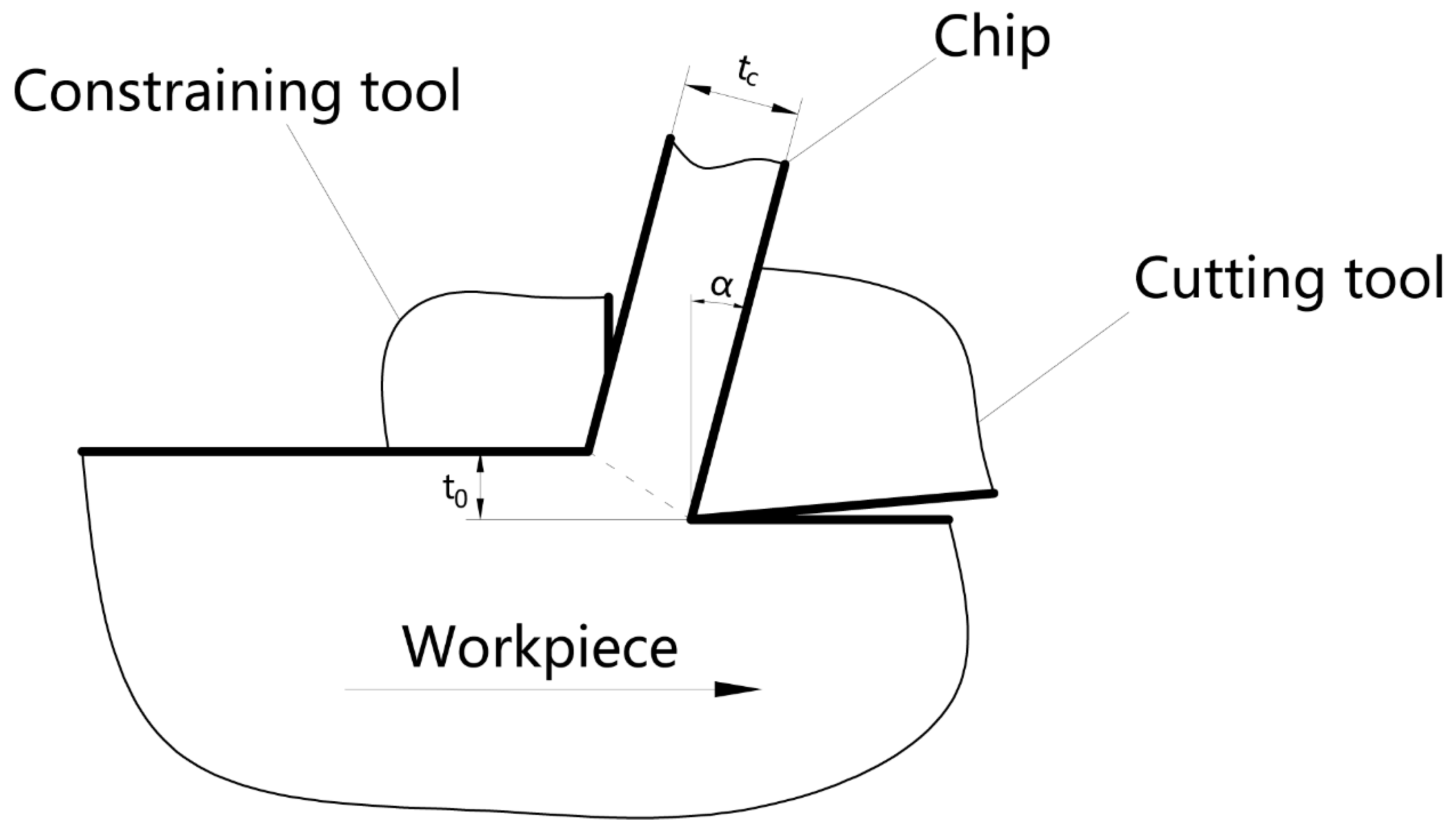
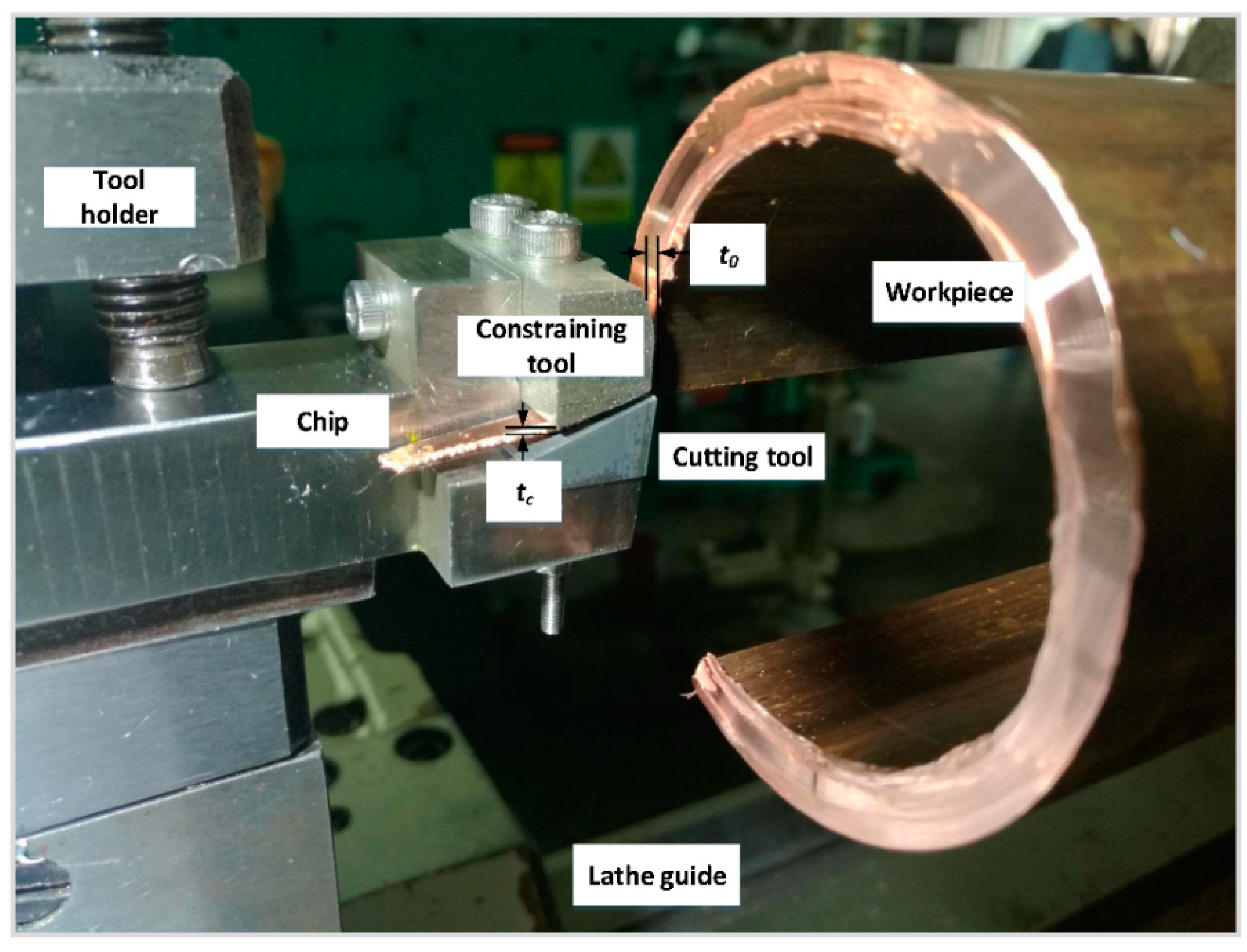
2.1. Preparation of UFG Copper

The experimental material used in this study was commercial pure copper, which was in the form of a circular tube with an external diameter of 70 mm, an internal diameter of 60 mm, and a length of 200 mm. This material had a melting point of 1083 °C and a relative density of 8.96 g / cm 3 , with the specific chemical composition shown in Table 1.
The chips were prepared by LSEM; the experimental setup is shown in Figure 2. The combined cutting tool with a rake angle α of 10° was made of high-speed steel and manufactured by wire electrode cutting. During the LSEM process, the workpiece should be rotated slowly and steadily to avoid excess heat generation. The main cutting work is performed by the cutting tool, while the extrusion channel is formed by the cutting tool and the constraining tool. This channel can control the geometry of chips and make the strain more severe and uniform by extruding the chips. Strip-shaped chips with a specific length of approximately 40–50 mm can be successfully produced. Due to the friction between the rake face and the chip, the width of the surface next to the rake face is slightly wider than that next to the constraining tool. The chip compression ratio, which is another important parameter of LSEM, can be controlled by adjusting the undeformed chip thickness t 0 and the chip thickness t c . All of the LSEM experiments were carried out on a universal lathe C6140A (Guangzhou Machine Tool Works Co., Ltd., Guangdong, China), which can have a rotation speed as slow as 25 r/min and can be adjusted across a wide range, while machining oil SAE-30 (Exxon Mobil Corporation, Irving, TX, USA) was used as the lubricant and coolant. In addition, the rest of the cutting parameters were as follows: the undeformed chip thickness t 0 was 0.8 mm, the chip thickness t c was 1.2 mm, the chip compression ratio λ was 1.5, the cutting speed V c was 92 mm/s, the relief angle β was 5° and the depth of cutting a p was 5.0 mm.

2.2. Heat Treatment Process Route and Equipment

The UFG chips were in a thermodynamic metastable state due to the high stored energy. Heat treatment led to changes in the microstructure of the UFG chips enabling them to reach a steady state, as well as a partial or even complete loss of their excellent properties. In order to study thermal stability, the UFG chips prepared by LSEM were divided into two groups and subjected to isochronous and isothermal annealing treatments to analyze the effect of annealing temperature and holding time on the microstructure and hardness.
The first group was subjected to isochronous annealing treatment. The UFG chips were annealed for 1 h at 100–400 °C and subsequently cooled to room temperature in the furnace. The process parameters are shown in Table 2.
The second group was subjected to isothermal annealing treatment. The UFG chips were annealed for 10–240 min at 280 °C and subsequently cooled to room temperature in the furnace. The process parameters are shown in Table 3.
All annealing treatments were carried out in the vacuum atmosphere sintering furnace HMZ1700-30 (Advanced Corporation for Materials & Equipments Co., Ltd., Changsha, China). The temperature rating of the furnace was up to 1500 °C, and the temperature control program was reliable with a temperature control accuracy of ± 1   ° C . All heat treatment experiments were carried out under a nitrogen atmosphere to avoid the oxidation of the chips.

2.3. Characterization Methods of Microstructure and Hardness Test

The microstructure evolutions of pure copper after LSEM and annealing treatments were observed by a field emission scanning electron microscope NOVA NANOSEM 430 (Oxford Instruments, Abingdon, UK). After this, we used the AZtec EBSD system (Oxford Instruments, Abingdon, UK) and the data analysis software HKL-Channel5 (Oxford Instruments, Abingdon, UK) to obtain the inverse pole figure (IPF), recrystallization fraction, and average grain size for comprehensive analysis. In order to evaluate the deformed, substructured, and recrystallized fractions, the software measured the internal average misorientation angle within the grain. If the average angle in a grain exceeded the 2° that defines a subgrain, the grain was classified as “deformed”. Some grains consisted of subgrains whose internal misorientation was under 2° but the misorientation from subgrain to subgrain was above that threshold. In this case, the grain was classed as “substructured”. All of the remaining grains were classified as “substructured”. The straight and flat part in the center of the strip-shaped chip was cut by the wire cutting process to prepare the observation samples. Taking the side next to the rake face as the observation surface, we used the cool mosaic method to embed samples in acrylic in a rod shape with a diameter of 22 mm. The samples were mechanically ground with water-resistant abrasive paper with granularity of 600–5000 in 2 . After alkali cleaning, water-washing, acid cleaning, water-washing, and quick blow-drying, the samples were polished using an electrolytic polishing method, which had the following main parameters: the electrolyte consisted of 700 mL of phosphoric acid and 300 mL distilled water, the distance between the cathode and anode was approximately 80–100 mm, the voltage was 1.8 V, the electrolysis temperature was room temperature, and the stirring speed was 200 r/min with an electrolysis time of 7–10 min. Vickers hardness was measured with a load of 0.98 N (penetration time of 15 s) using a digital microscopic hardness tester MVS-1000D1 (Guangzhou YDYQ Precision Instruments Co., Ltd., Guangzhou, China). Ten hardness indentation points that were far from chip edges with sufficient clearances were used for the hardness test, with the average hardness value of these points considered as the chip hardness.

3. Results and Discussions

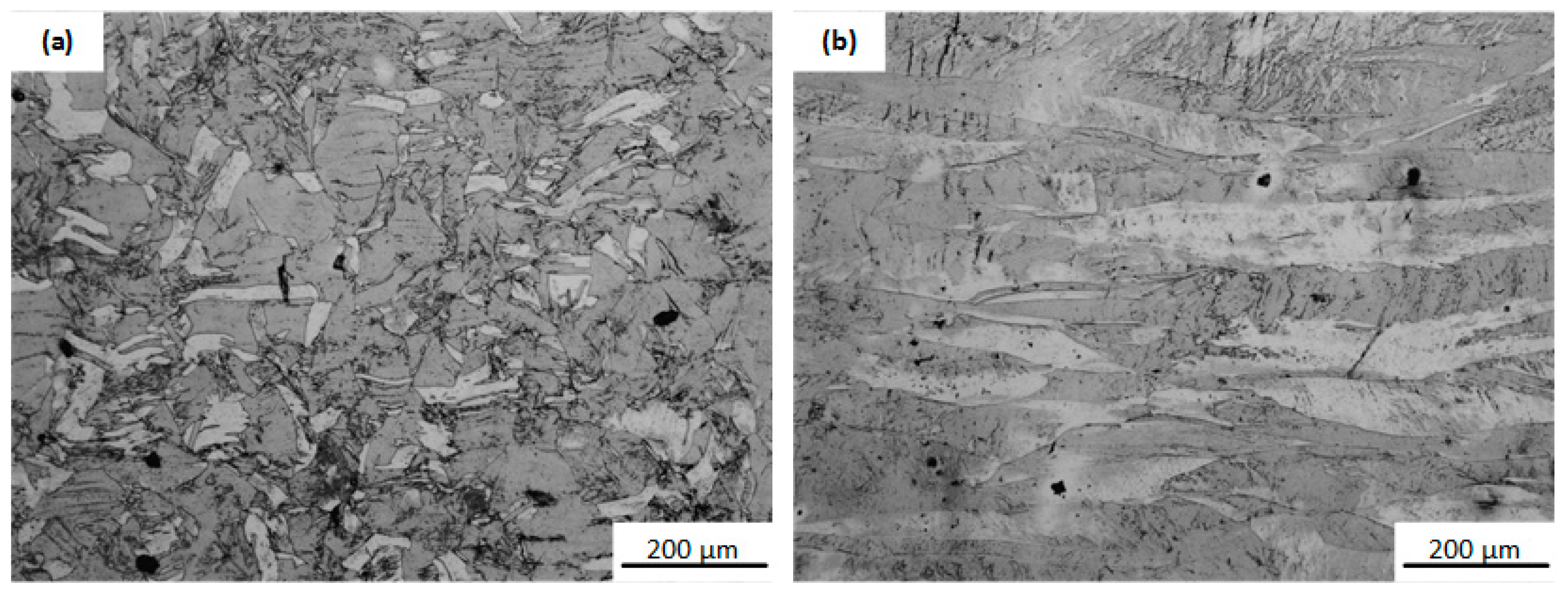
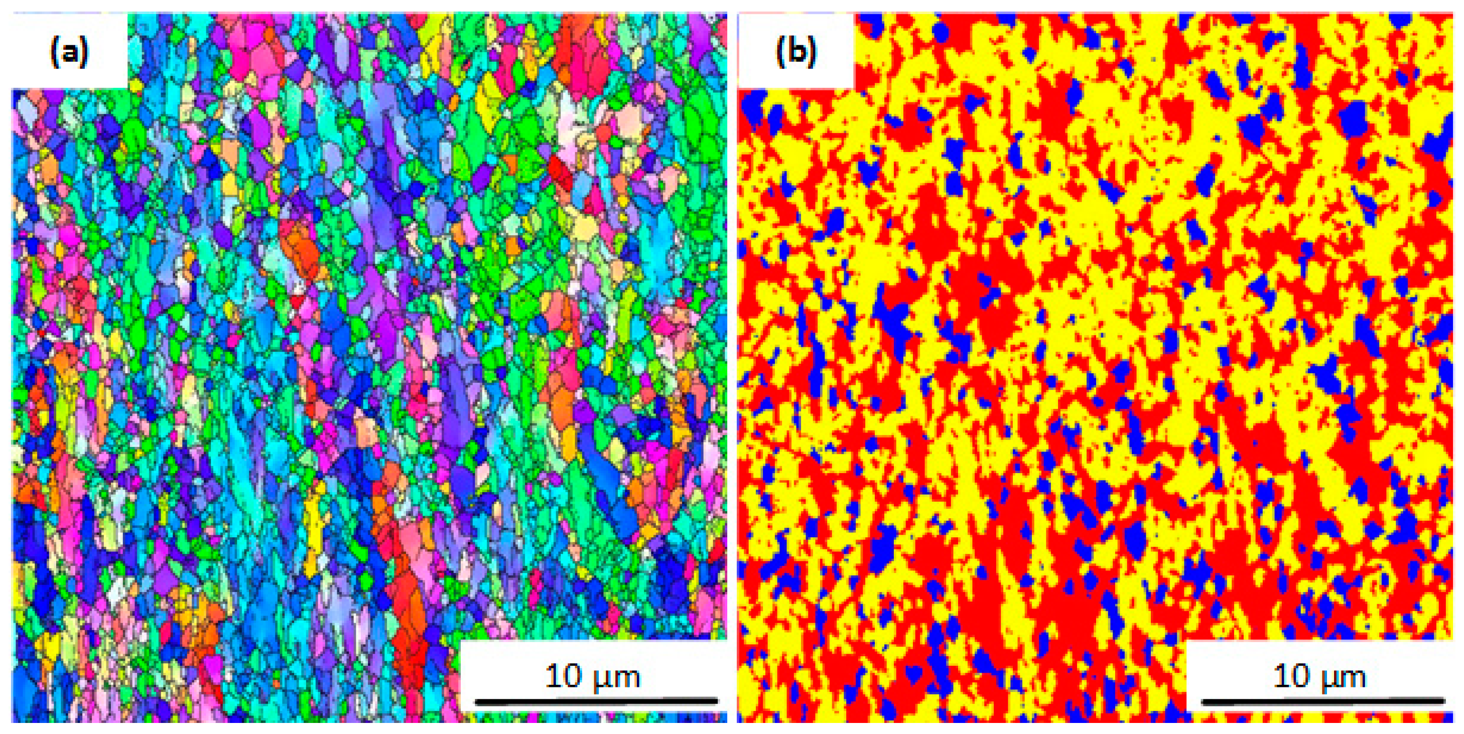
3.1. Grain Refinement by LSEM

The microstructure of pure copper raw materials is shown in Figure 3. The metallographic microscopy of the surface perpendicular to the axial direction of the pure copper tube is shown in Figure 3a. In this figure, well-defined grain boundaries can be observed, which suggests that the pure copper tube was composed of coarse equiaxed grains with a grain size of ~200 μ m . Figure 3b shows the metallographic microscopy of the surface parallel to the axial direction of the workpiece. It has a typical microstructure of rolling and stretching, which has long and coarse grains.
For comparison with the pure copper raw material, the microstructure of the UFG chips surface next to the rake face was observed. Figure 4a shows the inverse pole figure (IPF) maps from EBSD describing the microstructures of the UFG chips processed by LSEM. It can be seen that coarse equiaxed grains are refined into equiaxed grains with an average grain size of 0.7 μ m . This suggests that the material will be stretched and crushed to a certain degree after the shear deformation in the first deformation zone, before the friction between the rake face and the chip will cause the chip material to further stretch and crush. Thus, the grain will be further refined. Figure 4b shows the recrystallization fraction of the UFG chips without heat treatment. Fully recrystallized grains are shown in blue, deformed regions are in red, and substructured (recrystallized with subgrains) grains are in yellow. As shown in the figure, the microstructure of the chip had undergone severe deformation, while the proportion of deformed crystals and subgrains was extremely high. This shows that the deformation is severe through LSEM in order to refine the grains, while the UFG chips are in a thermodynamic metastable state due to the large amount of nonequilibrium grain boundaries and defects.
The hardness tests show that the Vickers hardness of pure copper significantly improved. The Vickers hardness value of the UFG chips was 146 HV, while the Vickers hardness value of the pure copper raw material was 85 HV.

3.2. Effect of Annealing Temperature

The annealing treatments of the UFG chips were conducted at different temperatures, including 160, 200, 240, 280, 320, and 360 °C for an annealing time of 1 h. Figure 5 shows the average grain sizes of the UFG chips in different annealing temperatures. It can be seen that, compared with the UFG chips without heat treatment, the grain size of the chips remained stable at 0.789 µm when annealing at 160 °C. When annealing at 160–280 °C, the grain size of the chips increased rapidly with an increase in the annealing temperature and the average grain size of the chips reached 2.14 μ m when the temperature reached 280 °C. Thereafter, the temperature was further increased to 320 °C and 360 °C, with the grain size growing to 3.6 μ m and 4.0 μ m , respectively.
Figure 6 shows the inverse pole figure (IPF) maps from EBSD describing the microstructures of the UFG chips processed by LSEM and annealed at different temperatures. It can be seen that the microstructure of the chips annealed at 160 °C was not significantly changed compared to the UFG chips without heat treatment. The equiaxed grains with an average grain size of 1.45 μ m gradually replaced the fine equiaxed grains, as shown in Figure 6b. With an increase in annealing temperature, the equiaxed grains became larger, as shown in Figure 6c. When the temperature reached 280 °C, the larger equiaxed grains started to form by annexing the fine equiaxed grains, which is shown in Figure 6d. When the temperature increased further, there were a higher number of larger equiaxed grains distributed uniformly, as depicted in Figure 6e,f.
Figure 7 shows the recrystallization fraction of the UFG chips at different annealing temperatures. It can be seen that compared with the chips without heat treatment, the chips annealed at 160 °C did not exhibit obvious changes and were mainly composed of deformed grains and subgrains. When annealing at 200 °C, the deformed grains almost disappeared and the number of subgrains was obviously reduced. At the same time, the chips could be determined to have a partial recrystallization structure due to the increasing recrystallization fraction. Thereafter, almost all of the chips started to be fully recrystallized when annealing at temperatures above 240 °C. Therefore, the chips were still in the recovery stage at temperatures below 160 °C, before reaching the recrystallization stage with an increase in the annealing temperature. The recrystallization was nearly completed at 240 °C.
Figure 8 shows the Vickers hardness values and the recrystallization fractions of the UFG chips at different annealing temperatures. The Vickers hardness values are 146, 145, 100, 81, 71, 63, and 61 HV, respectively. The recrystallization fractions are 11 % , 11 % , 70 % , 90 % , 94 % , 92 % , and 98 % , respectively. It can be seen that the Vickers hardness values and the recrystallization fractions of the chips annealed at 160 °C were not obviously changed compared with the chips before heat treatment. The recrystallization fraction of the chips obviously increased and the Vickers hardness value sharply decreased when the annealing temperature increased from 160 °C to 240 °C Finally, the recrystallization fraction of the chips did not change much and the Vickers hardness value decreased slowly when annealing at temperatures above 240 °C.
Based on the results of these experiments, it can be considered that the UFG chips prepared by LSEM are in the recovery stage at temperatures below 160 °C, while the majority of them are in the recrystallization stage at 200 °C and close to completing the recrystallization stage. After a further increase in the temperature, they move into the grain growth stage. When the temperature is below 160 °C, there are migrations of point defects within a small distance. The interaction between the point defects and dislocations disappears due to the annihilation of the point defects. Besides, the dislocations transform from high energy chaotic arrangements into low regular arrangements, which leads to a decrease in the density of dislocations. During the recovery stage, the annihilation and rearrangement of the dislocations causes a decrease in the dislocation density. The internal stress decreases and the material strength does not change too much, with a slight improvement in the material plasticity in the case of a small reduction in dislocation density. Therefore, the microstructure and the Vickers hardness value have no obvious changes.
When the temperature is between 160 °C and 240 °C, the microstructures obviously change due to the elevated temperatures. New dislocation-free equiaxed grains are formed in large deformation regions, accompanied by the disappearance of the strain hardening phenomenon. These then grow and consume the old grains, resulting in a new grain structure with a low dislocation density. The mechanical properties and physical properties of the materials are restored to their initial states. The grains are much more thermodynamically stable than before and thus the recrystallization fraction continuously increases and the Vickers hardness value decreases dramatically.
When the temperature is above 240 °C, the UFG chips are almost entirely recrystallized and the recrystallization fraction does not change much. The dislocation-free equiaxed grains start annexing each other and grow larger with the increasing annealing temperature. The grain boundaries assume a lower energy configuration. The total interface energy of the materials spontaneously decreases and the Vickers hardness value continues to decrease due to the grain growth at this time.

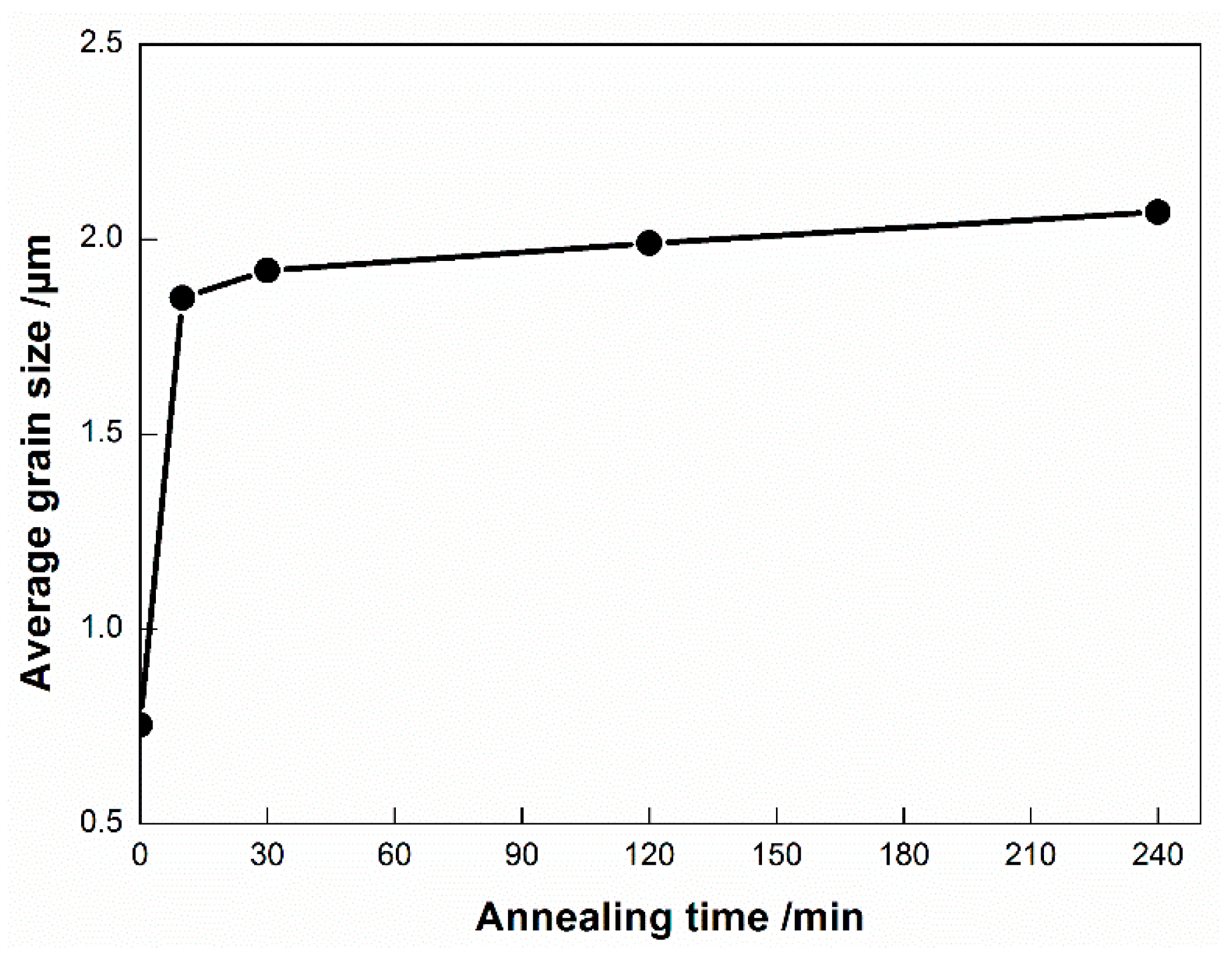
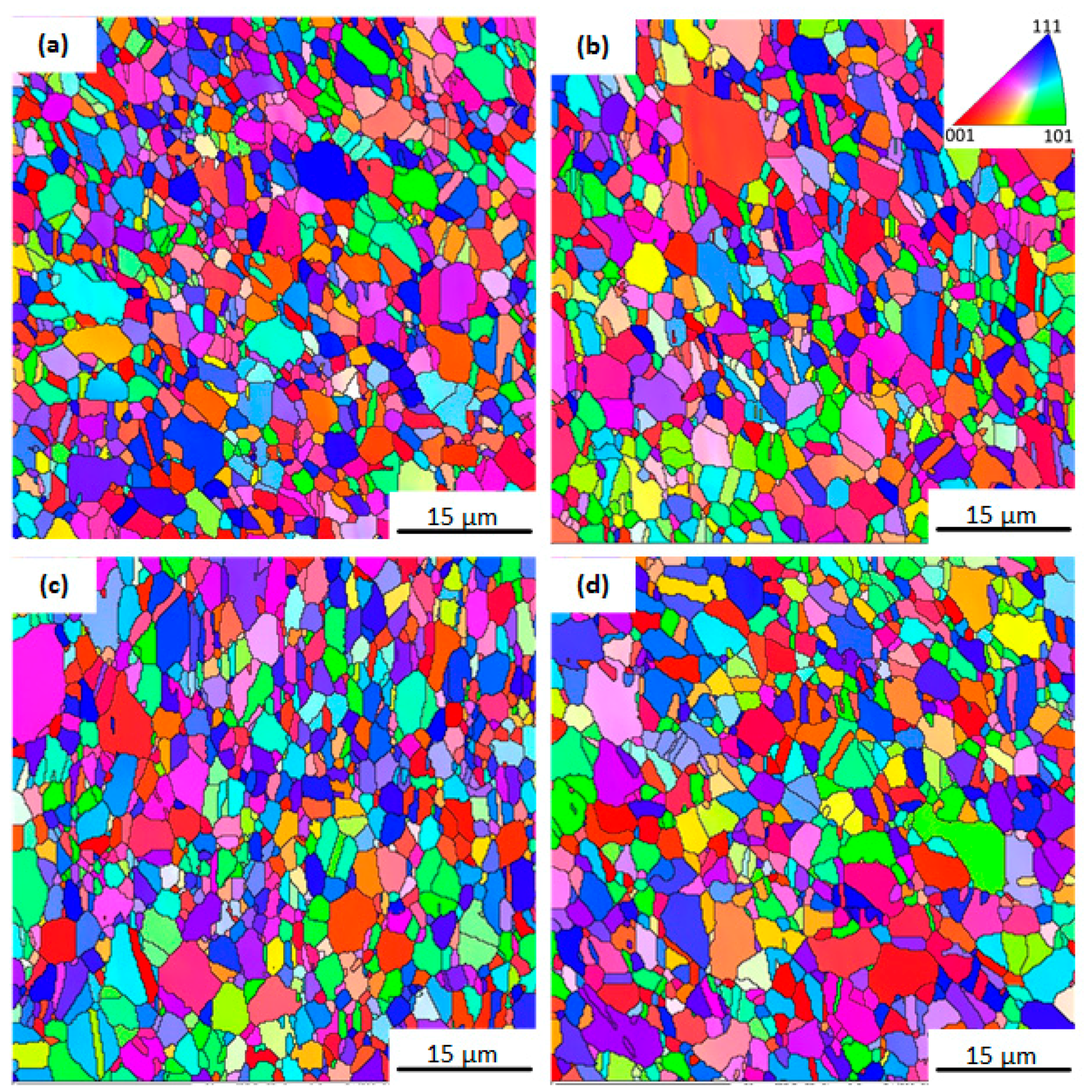
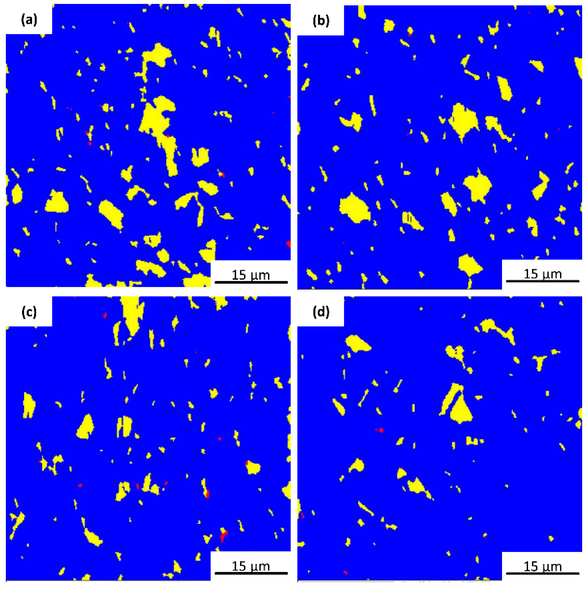
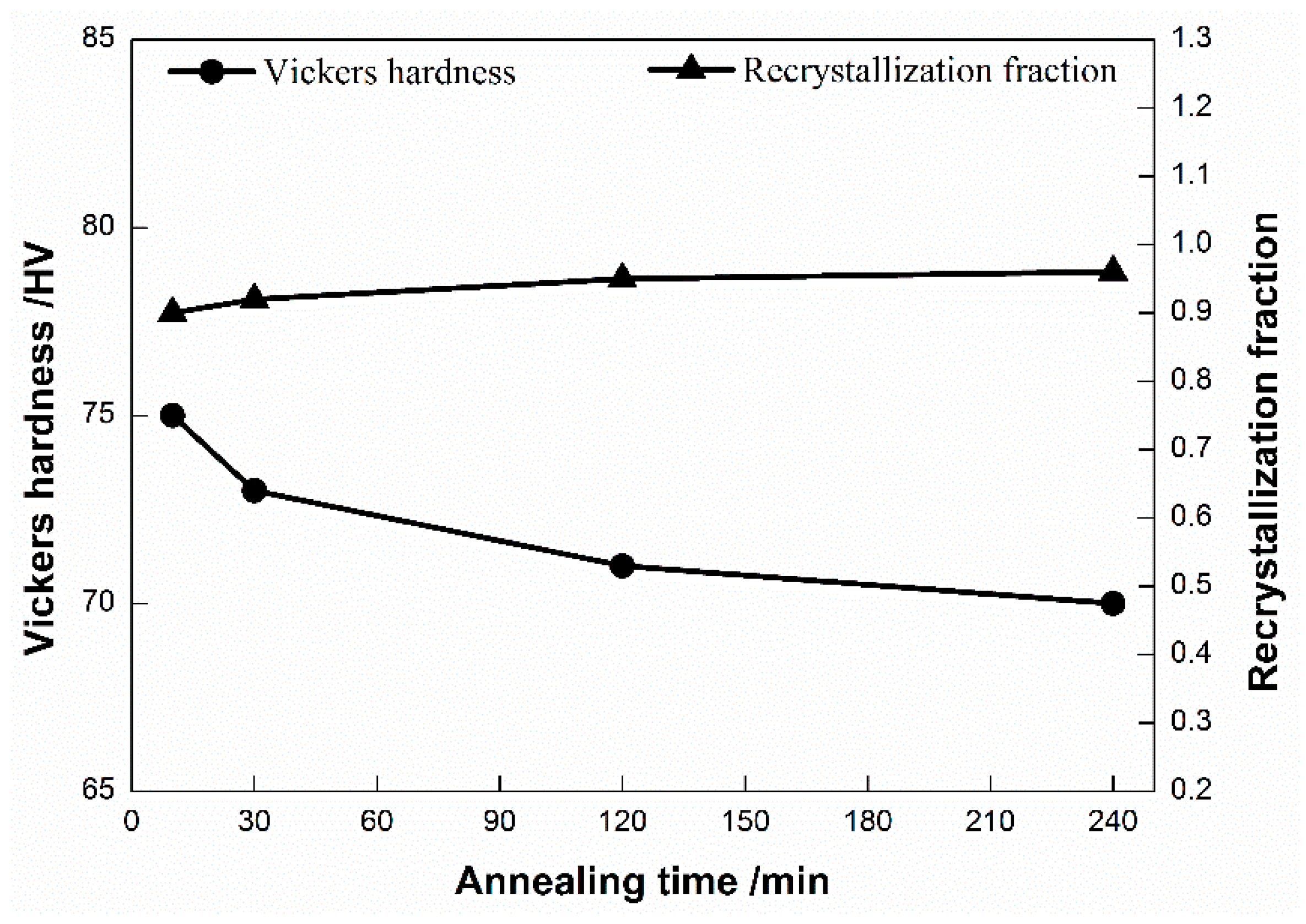
3.3. Effect of Annealing Time

The average grain size of the UFG chips with annealing treatments for different times is shown in Figure 9. After going through the annealing treatments for 10, 30, 120, and 240 min at 280 °C, the average grain sizes are 1.85, 1.92, 1.99, and 2.07 μ m , respectively. Compared with the chips before annealing treatment (0 min annealing time), the grain size of the chips annealed at 280 °C for 10 min display an apparent change as they grow from 0.754 μ m to 1.85 μ m . As the annealing time is prolonged to 30 min, the grain size slightly increases. However, the average grain size has few changes with a further extension in the annealing time.
The inverse pole figure (IPF) maps of the UFG chips prepared by LSEM are shown in Figure 10. After annealing at 280 °C for 10 min, the microstructure of the chips changed obviously as the fine equiaxed grains before the annealing treatment were replaced by new larger equiaxed grains, so the orientation of the microstructure was cluttered and the shear direction was rendered inconspicuous. With a further increase in the annealing time, the microstructure became more uniform.
The recrystallization fraction of the UFG chips annealed for different times is shown in Figure 11. As shown in the figure, after annealing at 280 °C for 10 min, the deformed grains had already disappeared and the proportion of subgrains decreased significantly, while a large number of recrystallized grains appeared. With a prolonged annealing time, the proportion of subgrains continued to fall and the number of recrystallization structure continuously increased. According to the recrystallization fraction, it can be roughly estimated that the UFG chips had already recrystallized after annealing at 280 °C for 10 min, before the recrystallization process was carried out to completion.
The Vickers hardness values and the recrystallization fractions of the UFG chips annealed at 280 °C for different times are shown in Figure 12. After annealing at 280 °C for 10, 30, 120, and 240 min, the Vickers hardness values of the UFG chips were 75, 73, 71, and 70 HV and the recrystallization fractions were 90 % , 92 % , 95 % , and 96 % , respectively. Compared with the chips before the annealing treatment, it can be clearly seen that the recrystallization fraction rose and the Vickers hardness value suddenly dropped. Hereafter, the recrystallization fraction slightly changed and the Vickers hardness value exhibited a small decrease with the increase in annealing time.
According to the consequences of the experiments above, it can be said that the UFG chips prepared by LSEM already started to recrystallize, before the recrystallization process was completed along with the increase in the annealing time. Therefore, there was a large quantity of new dislocation-free equiaxed grains in large deformation regions after annealing for 10 min. These grains grow by annexing surrounding deformed grains and they do not completely recrystallize because the time is relatively short. When the annealing time is extended to 30 min, the nucleation and grain growth during recrystallization are more sufficient and the recrystallization is nearly completed. With a further increase in the annealing time, the grain size increases slightly and the grain growth is limited because the annealing temperature does not rise further. The grain size reaches a stable value of 2 μ m , while the Vickers hardness value reaches a stable value around 70 HV.

4. Conclusions

In this study, the LSEM process using a combined cutting tool with a rake angle of 10 ° and a chip compression ratio of 1.5 was conducted to prepare UFG pure copper chips. In order to study the thermal stability of the UFG chips, a series of annealing treatments was carried out at different temperatures for different periods of time. Based on the above discussions and analysis, the following conclusions are drawn.
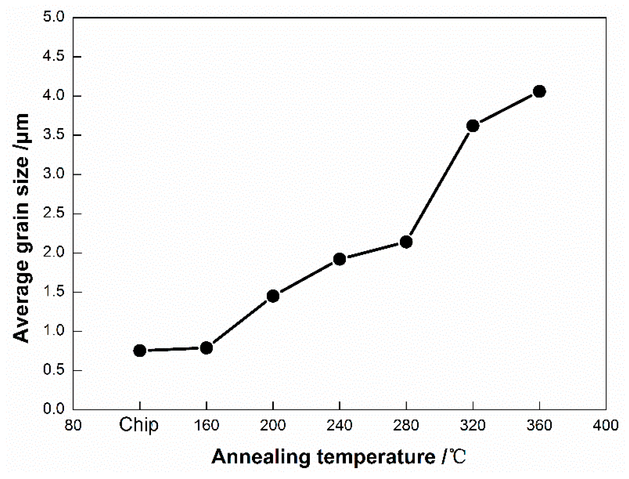
  • Compared to pure copper raw materials, the UFG chips prepared by LSEM are greatly refined. During the LSEM process, due to the shearing and friction introduced by the combined cutting tool, the coarse equiaxed structures are transformed into fine equiaxed structures with the grain size being refined from 100 μ m to 0.3–0.7 μ m . Furthermore, the Vickers hardness value of the chips is significantly increased because of the grain size reduction.
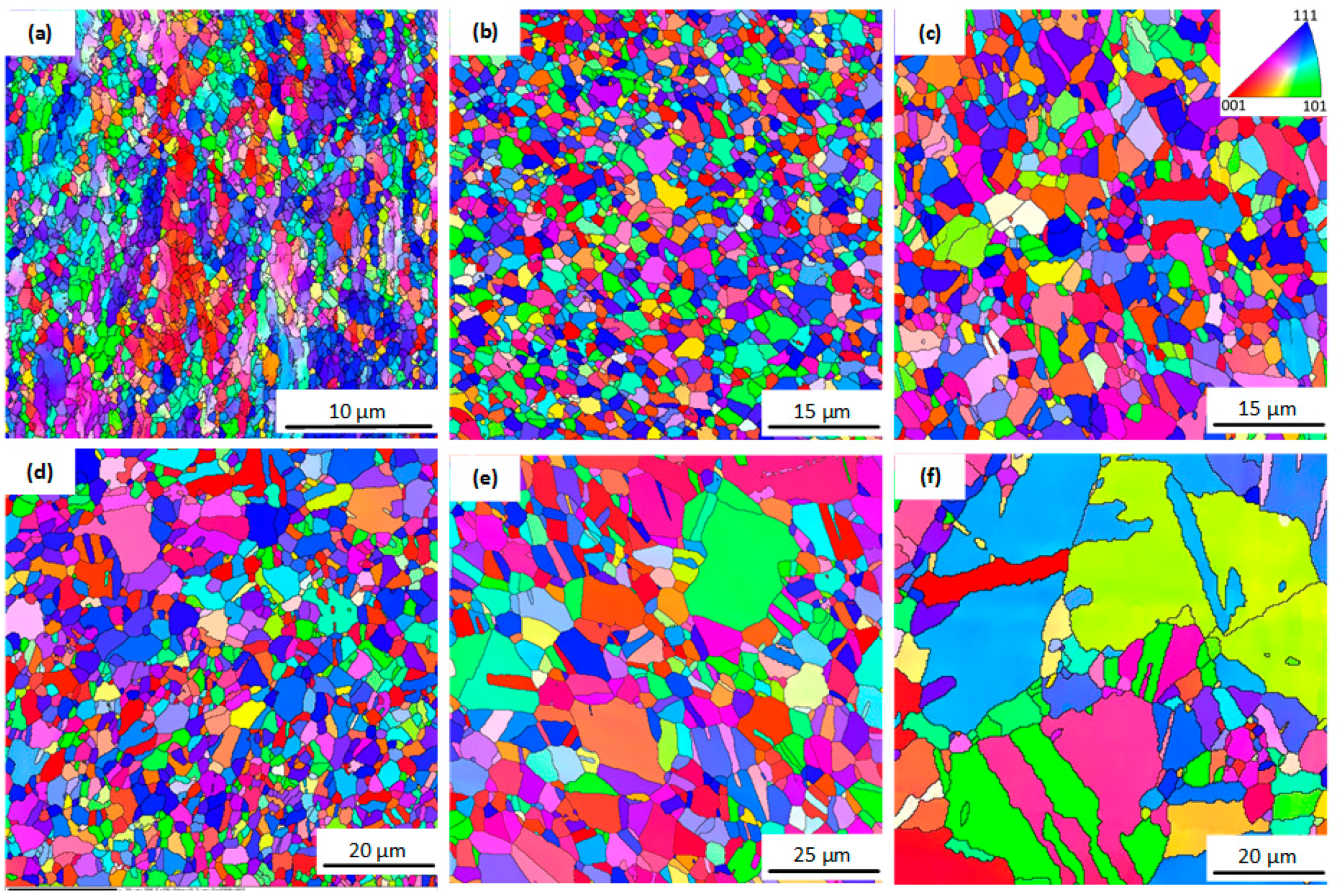
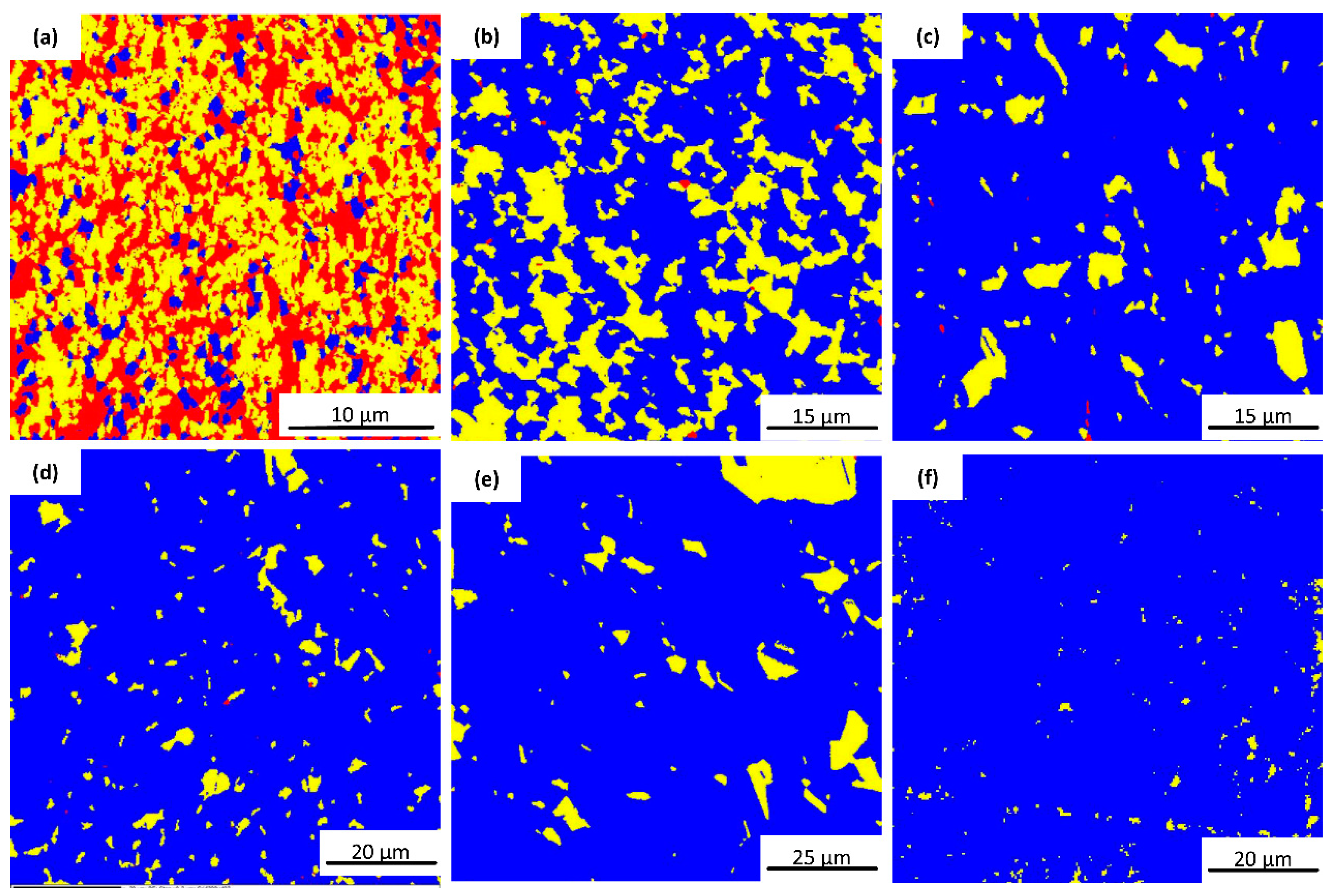
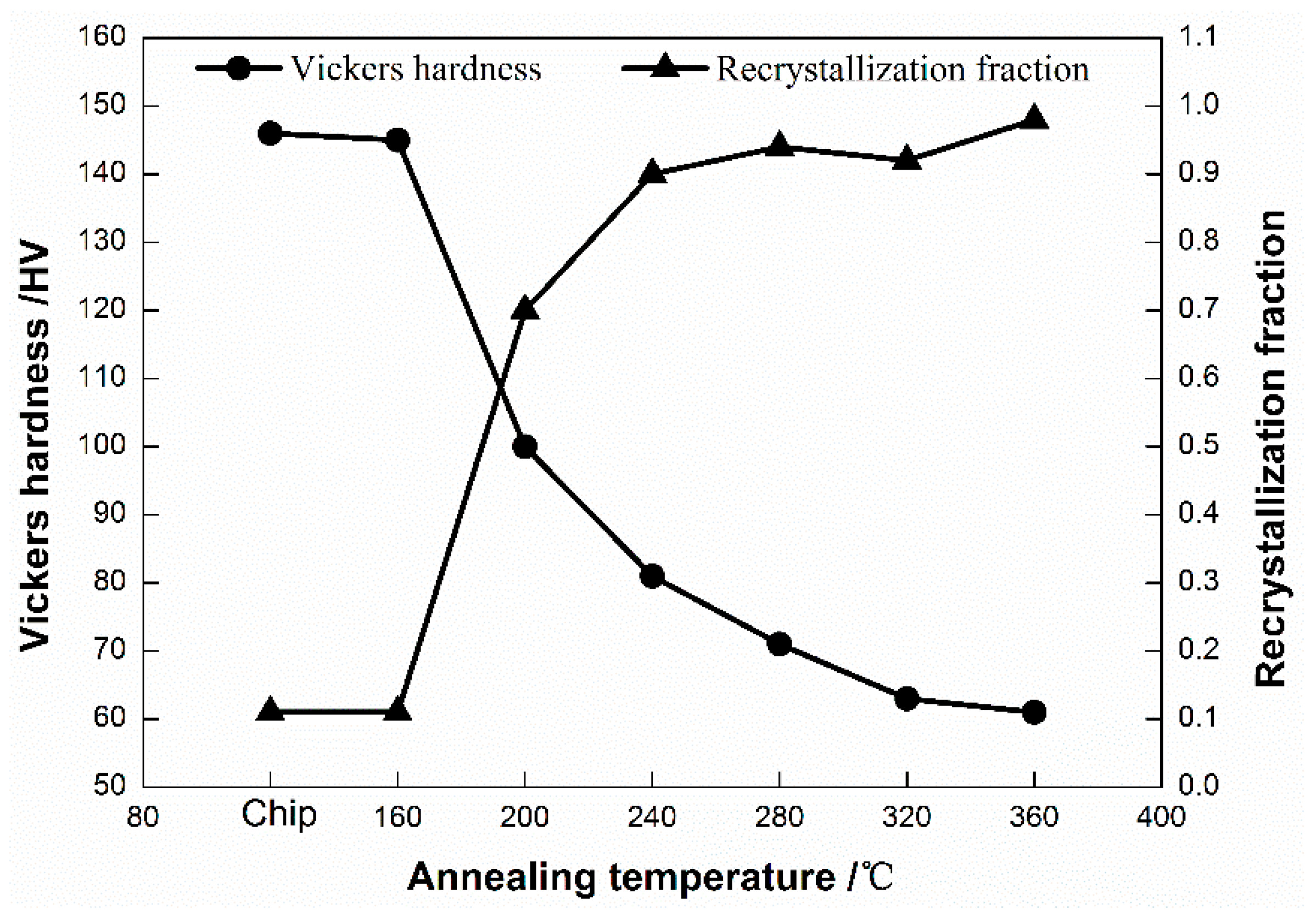
  • Annealing temperature has an important impact on the microstructure and hardness of the UFG chips. As the temperature rises, recrystallized grains gradually replace deformed grains and subgrains. With this increase in the grain size, the Vickers hardness value experiences a slight decrease, a sharp drop, and then a relatively slow decline. The UFG chips can maintain high hardness when annealing at temperatures up to 160 °C, although the hardness starts to be reduced when the temperature reaches above 200 °C.
  • When annealing at 280 °C, the chips start to recrystallize quickly. After holding the temperature for 10 min, most grains have already had a recrystallized structure. Almost all new dislocation-free equiaxed grains are formed, while the grain size reaches 1.85 μ m at this time. With a prolonged incubation time, the microstructure of the chips becomes more uniform, the grain size reaches a stable level around 2 μ m , and the Vickers hardness value reaches a stable value around 70 HV.

Author Contributions

B.W. initiated work plan, performed experiments, analyzed data, and wrote this paper; B.C. performed experiments and provided manuscript proofreading; Z.Z. conceived and designed experiments, performed experiments, and analyzed data; S.L. performed experiments; W.D. helped to conceive the present work and proofread the manuscript.

Acknowledgments

This work was financially supported by the National Natural Science Foundation of China (51375174), Fundamental Research Funds for Central Universities (2017ZD024), and the Natural Science Foundation of Guangdong Province (s2013050014163, 2017A030313260).

Conflicts of Interest

The authors declare no conflict of interest.

References

  1. Kumar, K.S.; Swygenhoven, H.V.; Suresh, S. Mechanical behavior of nanocrystalline metals and alloys. Acta Mater. 2003, 51, 5743–5774. [Google Scholar] [CrossRef]
  2. Kobayashi, S.; Tsurekawa, S.; Watanabe, T. A new approach to grain boundary engineering for nanocrystalline materials. Beilstein J. Nanotechnol. 2016, 7, 1829–1849. [Google Scholar] [CrossRef] [PubMed]
  3. Valiev, R.Z.; Estrin, Y.; Horita, Z.; Langdon, T.G.; Zehetbauer, M.J.; Zhu, Y. Producing Bulk Ultrafine-Grained Materials by Severe Plastic Deformation: Ten Years Later. JOM 2016, 68, 1216–1226. [Google Scholar] [CrossRef]
  4. Beygelzimer, Y.; Varyukhin, V.; Synkov, S.; Orlov, D. Useful properties of twist extrusion. Mater. Sci. Eng. A 2009, 503, 14–17. [Google Scholar] [CrossRef]
  5. Zhilyaev, A.P.; Langdon, T.G. Using high-pressure torsion for metal processing: Fundamentals and applications. Prog. Mater. Sci. 2008, 53, 893–979. [Google Scholar] [CrossRef]
  6. Tsuji, N.; Saito, Y.; Lee, S.-H.; Minamino, Y. ARB (Accumulative Roll-Bonding) and other new Techniques to Produce Bulk Ultrafine Grained Materials. Adv. Eng. Mater. 2010, 5, 338–344. [Google Scholar] [CrossRef]
  7. Gashti, S.O.; Fattah-Alhosseini, A.; Mazaheri, Y.; Keshavarz, M.K. Effects of grain size and dislocation density on strain hardening behavior of ultrafine grained AA1050 processed by accumulative roll bonding. J. Alloys Compd. 2016, 658, 854–861. [Google Scholar] [CrossRef]
  8. Valiev, R.Z.; Langdon, T.G. Principles of equal-channel angular pressing as a processing tool for grain refinement. Prog. Mater. Sci. 2006, 51, 881–981. [Google Scholar] [CrossRef]
  9. Liu, H.; Ju, J.; Lu, F.; Yan, J.; Bai, J.; Jiang, J.; Ma, A. Dynamic precipitation behavior and mechanical property of an Mg94Y4Zn2 alloy prepared by multi-pass successive equal channel angular pressing. Mater. Sci. Eng. A 2017, 682, 255–259. [Google Scholar] [CrossRef]
  10. Deng, W.J.; Xia, W.; Li, C.; Tang, Y. Ultrafine Grained Material Produced by Machining. Mater. Manuf. Process. 2010, 25, 355–359. [Google Scholar] [CrossRef]
  11. Deng, W.J.; Xia, W.; Li, C.; Tang, Y. Formation of ultra-fine grained materials by machining and the characteristics of the deformation fields. J. Mater. Process. Technol. 2009, 209, 4521–4526. [Google Scholar] [CrossRef]
  12. Iglesias, P.; Bermúdez, M.D.; Moscoso, W.; Rao, B.C.; Shankar, M.R.; Chandrasekar, S. Friction and wear of nanostructured metals created by large strain extrusion machining. Wear 2007, 263, 636–642. [Google Scholar] [CrossRef]
  13. Iglesias, P.; Bermúdez, M.D.; Moscoso, W.; Chandrasekar, S. Influence of processing parameters on wear resistance of nanostructured OFHC copper manufactured by large strain extrusion machining. Wear 2010, 268, 178–184. [Google Scholar] [CrossRef]
  14. Moscoso, W.; Shankar, M.R.; Mann, J.B.; Compton, W.D.; Chandrasekar, C.S. Bulk nanostructured materials by large strain extrusion machining. J. Mater. Res. 2007, 22, 201–205. [Google Scholar] [CrossRef]
  15. Chiffre, L.D. Extusion-cutting. Int. J. Mach. Tool Des. Res. 1976, 16, 137–144. [Google Scholar] [CrossRef]
  16. Chiffre, L.D. Extrusion cutting of brass strips. Int. J. Mach. Tool Des. Res. 1983, 23, 141–151. [Google Scholar] [CrossRef]
  17. Sevier, M.; Yang, H.T.Y.; Moscoso, W.; Chandrasekar, S. Analysis of Severe Plastic Deformation by Large Strain Extrusion Machining. Metall. Mater. Trans. A 2008, 39, 2645–2655. [Google Scholar] [CrossRef]
  18. Guo, Y.; Efe, M.; Moscoso, W.; Sagapuram, D.; Trumble, K.P.; Chandrasekar, S. Deformation field in large-strain extrusion machining and implications for deformation processing. Scr. Mater. 2012, 66, 235–238. [Google Scholar] [CrossRef]
  19. Cai, S.L.; Chen, Y.; Ye, G.G.; Jiang, M.Q.; Wang, H.Y.; Dai, L.H. Characterization of the deformation field in large-strain extrusion machining. J. Mater. Process. Technol. 2015, 216, 48–58. [Google Scholar] [CrossRef]
  20. Deng, W.J.; Li, Q.; Li, B.L.; Xie, Z.C.; He, Y.T.; Tang, Y.; Xia, W. Thermal stability of ultrafine grained aluminium alloy prepared by large strain extrusion machining. Mater. Sci. Technol. 2014, 30, 850–859. [Google Scholar] [CrossRef]
  21. Zhang, J.Y.; Li, B.L.; Zou, Z.J.; Zou, T.; Deng, W.J. Grain Refinement and Thermal Stability of AISI1020 Strips Prepared by Large Strain Extrusion Machining. Mater. Sci. Forum 2016, 836–837, 509–521. [Google Scholar] [CrossRef]
  22. Gubicza, J.; Dobatkin, S.V.; Khosravi, E.; Kuznetsov, A.A.; Lábár, J.L. Microstructural stability of Cu processed by different routes of severe plastic deformation. Mater. Sci. Eng. A 2011, 528, 1828–1832. [Google Scholar] [CrossRef]
  23. Tan, G.; Kalay, Y.E.; Gür, G.H. Long-Term Thermal Stability of Equal Channel Angular Pressed 2024 Aluminum Alloy. Mater. Sci. Eng. A 2016, 677, 307–315. [Google Scholar] [CrossRef]
  24. Abib, K.; Azzeddine, H.; Tirsatine, K.; Baudin, T.; Helbert, A.L.; Brisset, F.; Alili, B.; Bradai, D. Thermal stability of Cu-Cr-Zr alloy processed by equal-channel angular pressing. Mater. Charact. 2016, 118, 527–534. [Google Scholar] [CrossRef]
  25. Čížek, J.; Procházka, I.; Cieslar, M.; Kužel, R.; Kuriplach, J.; Chmelík, F.; Stulíková, I.; Bečvář, F.; Melikhova, O.; Islamgaliev, R.K. Thermal stability of ultrafine grained copper. Phys. Rev. B 2002, 65, 094106. [Google Scholar] [CrossRef]
  26. Tang, L.; Zhao, Y.; Islamgaliev, R.K.; Valiev, R.Z.; Zhu, Y.T. Microstructure and thermal stability of nanocrystalline Mg-Gd-Y-Zr alloy processed by high pressure torsion. J. Alloys Compd. 2017, 721. [Google Scholar] [CrossRef]
Figure 1. Large strain extrusion machining (LSEM) process.
Metals 08 00381 g001
Figure 2. Setup for LSEM.
Metals 08 00381 g002
Figure 3. Microstructure of pure copper raw material and chips: (a) the surface perpendicular to the axial direction; (b) the surface parallel to the axial direction.
Metals 08 00381 g003
Figure 4. Microstructure of ultrafine grained (UFG) chips prepared by LSEM: (a) the inverse pole figure (IPF); (b) the recrystallization fraction.
Metals 08 00381 g004
Figure 5. Grain size evolution at different annealing temperatures.
Metals 08 00381 g005
Figure 6. The inverse pole figures (IPFs) at different temperatures: (a) 160 °C; (b) 200 °C; (c) 240 °C; (d) 280 °C; (e) 320 °C; and (f) 360 °C .
Metals 08 00381 g006
Figure 7. The recrystallization fractions at different annealing temperatures: (a) 160 °C; (b) 200 °C; (c) 240 °C; (d) 280 °C; (e) 320 °C; and (f) 360 °C .
Metals 08 00381 g007
Figure 8. Vickers hardness values and recrystallization fractions at different annealing temperatures.
Metals 08 00381 g008
Figure 9. Grain size evolution under different annealing times.
Metals 08 00381 g009
Figure 10. Inverse pole figures under different annealing times: (a) 10 min; (b) 30 min; (c) 120 min; and (d) 240 min.
Metals 08 00381 g010
Figure 11. Recrystallization fractions under different annealing times: (a) 10 min; (b) 30 min; (c) 120 min; and (d) 240 min.
Metals 08 00381 g011
Figure 12. Vickers hardness values and recrystallization fractions under different times.
Metals 08 00381 g012
Table 1. The chemical composition of pure copper (wt %).
CuZnPNiBiSnSbAsOPbFeS
99.950.0050.0020.0020.0020.0020.0020.0010.0010.0010.0010.0013
Table 2. Isochronous annealing treatment parameters.
Sample Number123456
Initial temperatureRoom temperature
Temperature rising rate10 °C/min
Target temperature160 °C200 °C240 °C280 °C320 °C360 °C
Holding time1 h
Table 3. Isothermal annealing treatment parameters.
Sample Number1234
Initial temperatureRoom temperature
Temperature rising rate10 °C/min
Target temperature280
Holding time10 min30 min120 min240 min

