1. Introduction
In the automobile industry, cold working dies are commonly used for manufacturing stamping parts. Cold working dies with the characteristics of large-scale, complication, and precision play an important role in the automobile manufacturing industry. Deformation, abrasion and cracking always inevitably occur on the large-scale cold working dies in service due to the complex loads from the manufacturing of the large parts [
1,
2,
3]. Undoubtedly, the failure of cold working dies always results in a substantial increase in manufacturing costs. The service life of large-scale cold working dies can be effectively extended by repair, which has a remarkable significance for improving the production efficiency and cutting the manufacturing costs [
4,
5].
Hence, the repair of cold working dies with low costs, high efficiency, and good mechanical properties has developed into important scientific issue. In the aspect of repair method, manual arc surfacing is the most commonly used method applied to repair cold working dies due to the convenient operation and low costs. However, the disadvantages of manual arc surfacing also attract wide concerns, including high arc temperature, fast cooling rate, and continuous cooling transformation, which can seriously deteriorate the mechanical properties of the heat affected zone [
6,
7,
8]. Therefore, the mechanical property of the repaired zone is the bottleneck that restricts the service life of cold working dies. In the aspect of material weldability, the materials used in the manufacture of dies usually contain large amounts of carbon and alloying elements, which result in a poor weldability of die material. In order to obtain good mechanical properties after the repair of cold working dies, repair technology got extensive attention in the past years [
9,
10].
In the previous studies, researchers tried to repair the automobile dies by laser welding, TIG welding, electron beam welding, PVD, plasma transfer arc, and so forth. Microstructure and mechanical properties in the repaired zone were also investigated widely. Pleterski et al. [
11] found that the retained austenite formed during the laser welding of AISI D2 die steels due to the fast cooling rate results in the decrease of microhardness in the surface coating. Preciado et al. [
12] used TIG welding to weld the P20 steel and VP50IM with different heat inputs (3.6–9.8 kJ/cm). The results showed that the uniformity of surface texture depends on the alloying elements and the repair conditions. Zou et al. [
13] used an electron beam welding method to treat the D2 die steels with a high-current pulsed electron beam, and an uniform melting layer consists of ultrafine graded austenite and nanoscale carbides were obtained after 25 pulses treatment. Panjan et al. found that PVD technology can improve the wear resistance of the drawing die [
14]. Fernandes et al. [
15] deposited the gray cast iron by plasma transfer arc technique to study the effect of arc current on the microstructure and performances in order to promote the quantity of precipitates and C flakes at the grain boundaries.
Several arc welding technologies have been successfully used to repair dies [
16], such as Shielded Metal Arc Welding (SMAW), Gas Metal Arc Welding (GMAW), Gas Tungsten Arc Welding (GTAW), and Laser Welding (LW). As one of the main reasons for repairing dies, parts presenting casting defects such as cracks/fissures or shrinkages in non-functional areas can be easily repaired by welding. However, the cost of the shield gas of welding process, such as GMAW, is higher than other methods. It is also sensitive to the oil and rust of base material and welding wire. The disadvantages of GTAW are low weld penetration depth, low deposition speed and low productivity. At the same time, the current carrying capacity of the tungsten electrode is poor. Excessive current will cause the tungsten to melt and evaporate, and the particles may enter the molten pool and cause pollution. The weld bead of LW is narrow and the deposition rate is low. Meanwhile, the equipment is expensive and it also has strict requirements for the operating position. Compared with the above methods, SMAW is the simplest repair method with the lowest cost often used in the automobile manufacturing industry [
17]. However, there are still few reports on the SMAW used for the repair of the large-scale cold working dies. For the 5Cr5MoV die steel, the optimization of parameter in repair process as well as the microstructure and the mechanical properties in the repaired zone still need to be investigated further.
As new cold working die steel, the microstructure of 5Cr5MoV die steel contains a large amount of tempered martensite and tempered sorbite (TS), exhibits high strength, and high wear resistance. During the production of automotive panels by cold working, the manufacturing process often causes wear, cracking, chipping, and other damages [
18,
19,
20,
21].
In this paper, the repair of 5Cr5MoV die steel was carried out by the SMAW method. The influence of welding heat input on the microstructure and mechanical properties was studied in order to improve the mechanical properties and the service life of 5Cr5MoV die steel by optimizing the heat input. It is hoped that the research in this paper can provide guidance for the repair of medium carbon alloy die steel.
4. Discussion
After the long-term service, chipping and other surface defects easily occur on the surface of cold working die, which result in the die failure and early retirement. Repair can effectively extend the life of dies, thereby greatly cutting the cost for the car manufacture. Surfacing is the most commonly used method for the die repair. However, surfacing process significantly affects the mechanical properties of the repaired zone, including weld zone, fusion zone, and heat affected zone. Heat input is the most important factor affecting the repaired zone, and also affecting the microstructure as well as the mechanical properties in the repaired zone.
Undoubtedly, heat input significantly influences the microstructure of the repaired zone. By the comparison of the microstructures, the dendrite size and the branch spacing in the weld metal increase with the increase of heat input [
23]. The variation of the dendrite size can be attributed to the changes of heat input, which significantly influence the cooling rate. In this aspect, a high heat input means a low cooling rate [
24], which can effectively reduce the growth time of dendrite, and it can provide enough time for the dendrite growth into the fusion zone. These columnar dendrites are the major microstructure in the weld. When the cooling temperature is below
Ar3, the austenite transforms into the secondary microstructure. Martensite with a small amount of retained austenite formed during the cooling process due to the high carbon content of the weld steel together with the rapid cooling rate. A low heat input always means a high cooling rate, which results in difficulty in the diffusion of the carbon in the austenite. Most carbon still left in the austenite in the form of the saturated solution increases the stability of austenite.
Moreover, heat input significantly affects the microstructure of the heat affected zone in the repaired zone. During the welding process, temperature in the complete quenching zone was above
Ac3. Therefore, with the increase of heat input, the heating speed was faster, that is to say, the holding time was longer and the homogenization of the microstructure was improved [
25,
26]. For the heat input of 6.6 kJ/cm, the chemical compositions in the austenite were more homogeneous and the carbon-rich micro-regions were eliminated. The martensite islands became larger, which also lead to increased strength significantly. In the welding process, the incomplete quenching zone was heated to
Ac1–
Ac3 and the homogenization of austenite turned poor under the condition of rapid heating. Under that condition, the ferrite was difficult to dissolve into the austenite. After the welding, temperature dropped rapidly and the austenite transformed into martensite. At this time, some ferrites not dissolved in the austenite retained and finally formed a microstructure mixed with martensite, ferrite, and retained austenite. Temperature increases with the increase of heat input, and the increase of the element driving force promotes the dissolution of ferrite into austenite [
27]. As a result, the austenite transition becomes stable. With the further decreased of ferrite at the heat input of 6.6 kJ/cm, the microstructure turned more homogeneous. The tempering temperature is kept from the tempering temperature to
Ac1, i.e., 500 °C to
Ac1. With the increase of heat input, temperature in the tempering zone increased gradually, and the precipitation of carbides became more sufficient resulting in the deterioration of the regional performance.
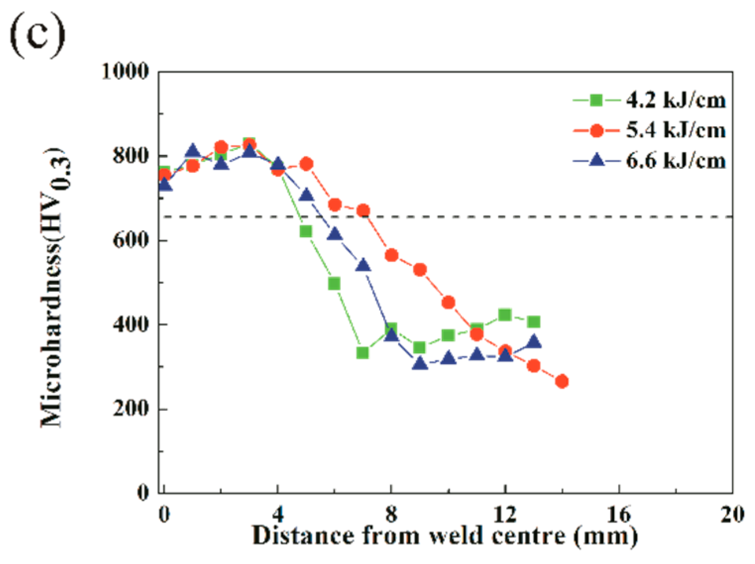
With the increase of heat input, the transformation of austenite in the complete quenching zone was complete, and thus the microhardness increased slightly, but with the further increase of heat input (6.6 kJ/cm), the grain size increased obviously [
28], which results in the decrease of microhardness. The decrease of microhardness in the incomplete quenching zone indicates that the softness of the heat affected zone occurred. The decrease of microhardness in the incomplete quenching zone can be attributed to the characteristics of ferrite.
With the increase of heat input, the content of ferrite dissolved in the austenite increased resulting in the microstructure homogenization, and the hardening tendency also increased. Temperature in the tempering zone rose with the increase of heat input [
29], which resulted in the precipitation of carbide particles at the grain boundary. Finally, the decomposition of martensite led to the decrease of microhardness in the tempering zone, which became lower than the base metal finally.
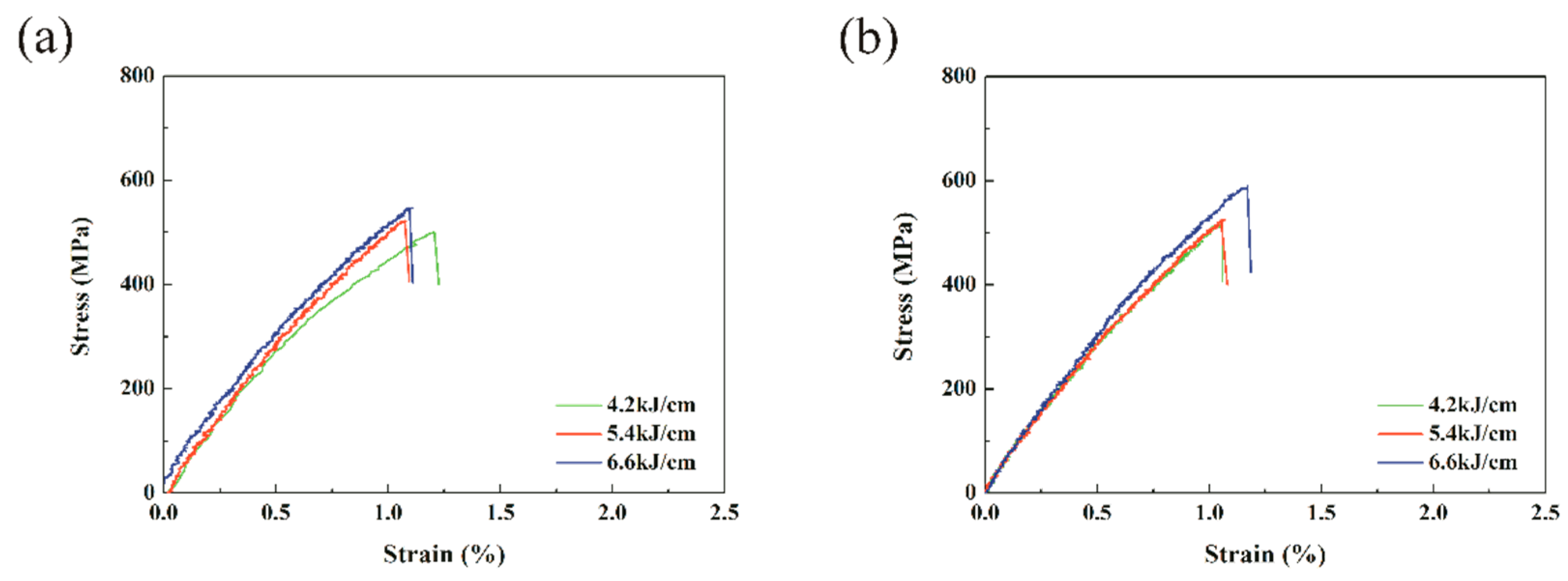
Tensile strength increased with the increase of heat input in the position of weld and heat affected zone. This is because the dendrites have sufficient time to grow into the fusion zone under high heat input with the low cooling rate. Meanwhile, the content of martensite in the weld increased, resulting in the promotion of strength. At the same time, due to the presence of large amounts of martensite, the ductility of steel was less than 3%.
With the increase of heat input, the content of austenite in the weld decreased at the position A. The austenite in the weld decreased gradually, and thus the microstructure became more homogeneous at high temperature input. For the tensile sample cut from the position B, the ration of weld decreased, on the contrary, the heat affected zone increased. With the increase of heat input, the microstructure became more homogeneous, and simultaneously the amount of ferrite phase decreased with the increase of lath martensite. At the position C, the tensile sample was cut from the tempering zone. With the increase of heat input, the increase of temperature drove the decomposition of martensite gradually. Therefore, the dislocation density decreased, and the ferrite recrystallized gradually. At the same time, secondary carbide precipitated and grew, which results in tensile strength and the elongation first decreases and then increases.
Author Contributions
Conceptualization, Y.L. (Yan Liang), Y.L. (Yaohui Liu) and Y.S.; Data curation, Y.L. (Yan Liang) and W.C.; Funding acquisition, Y.L. (Yaohui Liu); Investigation, Y.L. (Yan Liang); Methodology, Y.L. (Yan Liang); Supervision, Y.S.; Writing—original draft, Y.L. (Yan Liang); Writing—review & editing, Y.L. (Yan Liang).
Funding
This research was funded by the National Natural Science Foundation of China (Grant No. 50901035), and the Science and Technology Development Projects of Jilin Province (Grant No. 20140204042GX).
Conflicts of Interest
The authors declare no conflict of interest.
References
- Jhavar, S.; Paul, C.; Jain, N. Causes of failure and repairing options for dies and molds: A review. Eng. Fail. Anal. 2013, 34, 519–535. [Google Scholar] [CrossRef]
- Statharas, D.; Sideris, J.; Medrea, C.; Chicinaş, I. Microscopic examination of the fracture surfaces of a cold working die due to premature failure. Eng. Fail. Anal. 2011, 18, 759–765. [Google Scholar] [CrossRef]
- Geiger, M.; Falk, B. Prediction of service life and failure probability of cold forging tools. CIRP Ann. 2001, 50, 173–176. [Google Scholar] [CrossRef]
- Tušek, J.; Taljat, B.; Klobčar, D. How to extend the life of die-casting tools. Metalurgija 2006, 46, 67–71. [Google Scholar]
- Peças, P.; Henriques, E.; Pereira, B.; Lino, M.; Silva, M. Fostering the use of welding technology in the mould repair. In Proceedings of the RPD 2006-Building the Future by Innovation, Marinha Grande, Portugal, 13–15 November 2006. [Google Scholar]
- Branza, T.; Deschaux-Beaume, F.; Sierra, G.; Lours, P. Study and prevention of cracking during weld-repair of heat-resistant cast steels. J. Mater. Process. Technol. 2009, 209, 536–547. [Google Scholar] [CrossRef]
- Duchosal, A.; Deschaux-Beaume, F.; Lours, P.; Haro, S.; Fras, G. Analysis of weld-cracking and improvement of the weld-repair process of superplastic forming tools. Mater. Des. 2013, 46, 731–739. [Google Scholar] [CrossRef]
- Branza, T.; Deschaux-Beaume, F.; Velay, V.; Lours, P. A microstructural and low-cycle fatigue investigation of weld-repaired heat-resistant cast steels. J. Mater. Process. Technol. 2009, 209, 944–953. [Google Scholar] [CrossRef]
- Thompson, S. Handbook of mould, tool and die repair welding; Abington Publishing: Abington, England, 1999. [Google Scholar]
- Marlow, F.M. Welding fabrication & repair: Questions and answers; Industrial Press Inc.: New York, NY, USA, 2002. [Google Scholar]
- Pleterski, M.; Tusek, J.; Muhic, T.; Kosec, L. Laser cladding of cold-work tool steel by pulse shaping. J. Mater. Sci. Technol. 2011, 27, 707–713. [Google Scholar] [CrossRef]
- Preciado, W.T.; Nino Bohorquez, C.E. Repair welding of polymer injection molds manufactured in AISI P20 and VP50IM steels. J. Mater. Process. Technol. 2006, 179, 244–250. [Google Scholar] [CrossRef]
- Zou, J.; Grosdidier, T.; Zhang, K.; Dong, C. Mechanisms of nanostructure and metastable phase formations in the surface melted layers of a HCPEB-treated D2 steel. Acta Mater. 2006, 54, 5409–5419. [Google Scholar] [CrossRef]
- Panjan, P.; Boncina, I.; Bevk, J.; Cekada, M. PVD hard coatings applied for the wear protection of drawing dies. Surf. Coat. Technol. 2005, 200, 133–136. [Google Scholar] [CrossRef]
- Fernandes, F.; Lopes, B.; Cavaleiro, A.; Ramalho, A.; Loureiro, A. Effect of arc current on microstructure and wear characteristics of a Ni-based coating deposited by PTA on gray cast iron. Surf. Coat. Technol. 2011, 205, 4094–4106. [Google Scholar] [CrossRef]
- Gouveia, R.M.; Silva, F.J.; Paiva, O.C.; de Fátima Andrade, M.; Pereira, L.A.; Moselli, P.C.; Papis, K.J. Comparing the structure and mechanical properties of welds on ductile cast iron (700 MPa) under different heat treatment conditions. Metals 2018, 8, 72. [Google Scholar] [CrossRef]
- Gouveia, R.M.; Silva, F.J.; Paiva, O.C.; Andrade, M.F.; Silva, L.; Moselli, P.C.; Papis, K.J. Study of the heat-treatments effect on high strength ductile cast iron welded joints. Metals 2017, 7, 382. [Google Scholar] [CrossRef]
- Gagg, C.R.; Lewis, P.R. Wear as a product failure mechanism–overview and case studies. Eng. Fail. Anal. 2007, 14, 1618–1640. [Google Scholar] [CrossRef]
- MacCormack, C.; Monaghan, J. Failure analysis of cold forging dies using FEA. J. Mater. Process. Technol. 2001, 117, 209–215. [Google Scholar] [CrossRef]
- Ebara, R.; Takeda, K.; Ishibashi, Y.; Ogura, A.; Kondo, Y.; Hamaya, S. Microfractography in failure analysis of cold forging dies. Eng. Fail. Anal. 2009, 16, 1968–1976. [Google Scholar] [CrossRef]
- Pereira, M.P.; Yan, W.; Rolfe, B.F. Wear at the die radius in sheet metal stamping. Wear 2012, 274, 355–367. [Google Scholar] [CrossRef]
- Li, H.-R.; Sun, L.-G.; Zhu, L.-G.; Liu, Y.-S.; Li, Y.-G. Research on influential mechanism of HAZ impact toughness for shipbuilding steel with mg addition. Metals 2018, 8, 584. [Google Scholar] [CrossRef]
- Kumar, S.; Shahi, A.S. Effect of heat input on the microstructure and mechanical properties of gas tungsten arc welded AISI 304 stainless steel joints. Mater. Des. 2011, 32, 3617–3623. [Google Scholar] [CrossRef]
- Da Fonseca, G.S.; Rodrigues Barbosa, L.O.; Alves Ferreira, E.; Xavier, C.R.; de Castro, J.A. Microstructural, mechanical, and electrochemical analysis of duplex and superduplex stainless steels welded with the autogenous TIG process using different heat input. Metals 2017, 7, 538. [Google Scholar] [CrossRef]
- Peddle, B.; Pickles, C. Carbide and hardness development in the heat-affected zone of tempered and postweld heat-treated 2.25Cr-1Mo steel weldments. J. Mater. Eng. Perform. 2000, 9, 477–488. [Google Scholar] [CrossRef]
- Biro, E.; McDermid, J.R.; Embury, J.D.; Zhou, Y. Softening kinetics in the subcritical heat-affected zone of dual-phase steel welds. Metall. Mater. Trans. A 2010, 41A, 2348–2356. [Google Scholar] [CrossRef]
- Kou, S. Welding metallurgy, 2nd ed.; John Wiley & Sons, Inc.: Hoboken, NJ, USA, 2003. [Google Scholar]
- Banerjee, K.; Militzer, M.; Perez, M.; Wang, X. Nonisothermal austenite grain growth kinetics in a microalloyed X80 linepipe steel. Metall. Mater. Trans. A 2010, 41, 3161–3172. [Google Scholar] [CrossRef]
- Mohandas, T.; Reddy, G.M.; Kumar, B.S. Heat-affected zone softening in high-strength low-alloy steels. J. Mater. Process. Technol. 1999, 88, 284–294. [Google Scholar] [CrossRef]
Figure 1.
The flow chart of heat treatment process for 5Cr5MoV die steel.
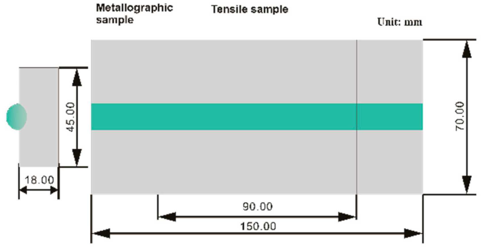
Figure 2.
Sampling position of the metallographic and tensile samples.
Figure 3.
Indents point distribution in the microhardness measurement.
Figure 4.
Sampling position and dimensions of tensile samples.
Figure 5.
Microhardness distribution on the cross section of samples weld: (a) face transverse; (b) root transverse; and (c) vertical.
Figure 6.
Stress-strain curve of weld joints. (a) Samples A; (b) Samples B; and (c) Samples C.
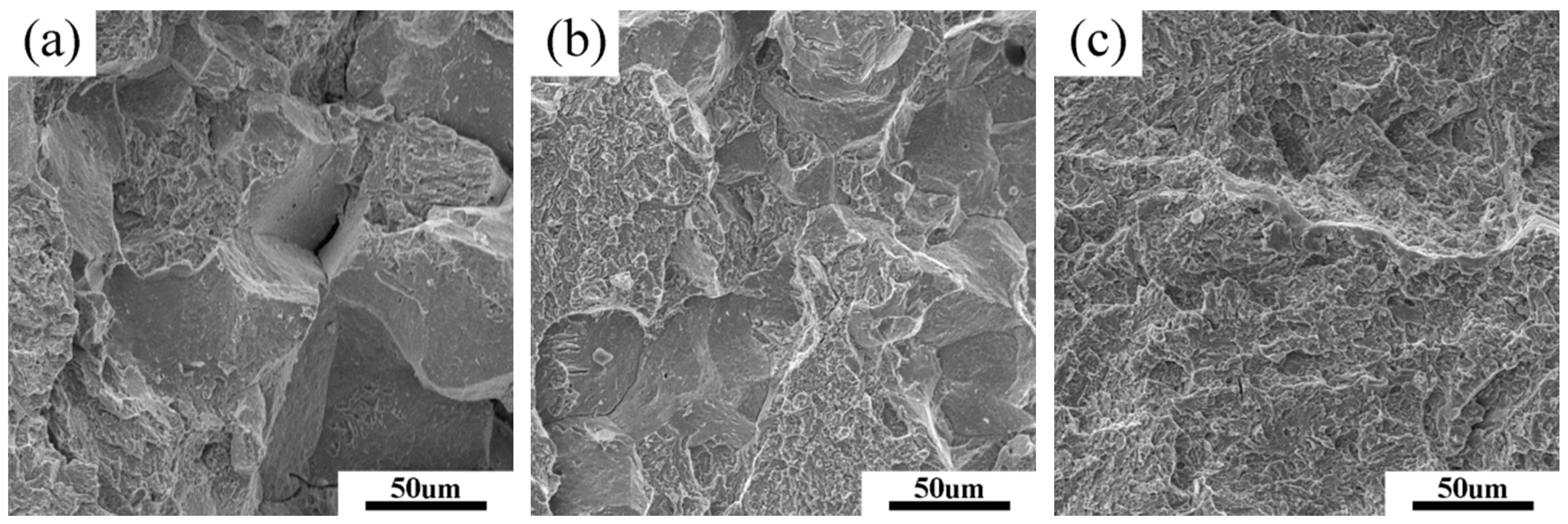
Figure 7.
Fractograph of the tensile sample with the heat input of 4.2 kJ/cm. (a,b) Fusion zone fracture; and (c) tempering zone fracture.
Figure 8.
Fractograph of the tensile sample with the heat input of 5.4 kJ/cm. (a,b) Fusion zone fracture; and (c) tempering zone fracture.
Figure 9.
Fractograph of the tensile sample with the heat input of 6.6 kJ/cm. (a,b) Fusion zone fracture; (c) tempering zone fracture; and (d) the corresponding EDS from the P1 point in (b).
Figure 10.
Microstructure of Weld bead at different heat inputs. (a) 4.2 kJ/cm, and (b) 5.4 kJ/cm, (c) 6.6 kJ/cm.
Figure 11.
Microstructure of fusion zone at different heat inputs. (a) 4.2 kJ/cm, and (b) 5.4 kJ/cm, (c) 6.6 kJ/cm.
Figure 12.
Microstructure of the complete quenching zone at different heat inputs. (a) 4.2 kJ/cm, and (b) 5.4 kJ/cm, (c) 6.6 kJ/cm.
Figure 13.
Microstructure of the incomplete quenching zone at different heat inputs. (a) 4.2 kJ/cm, (b) 5.4 kJ/cm, and (c) 6.6 kJ/cm.
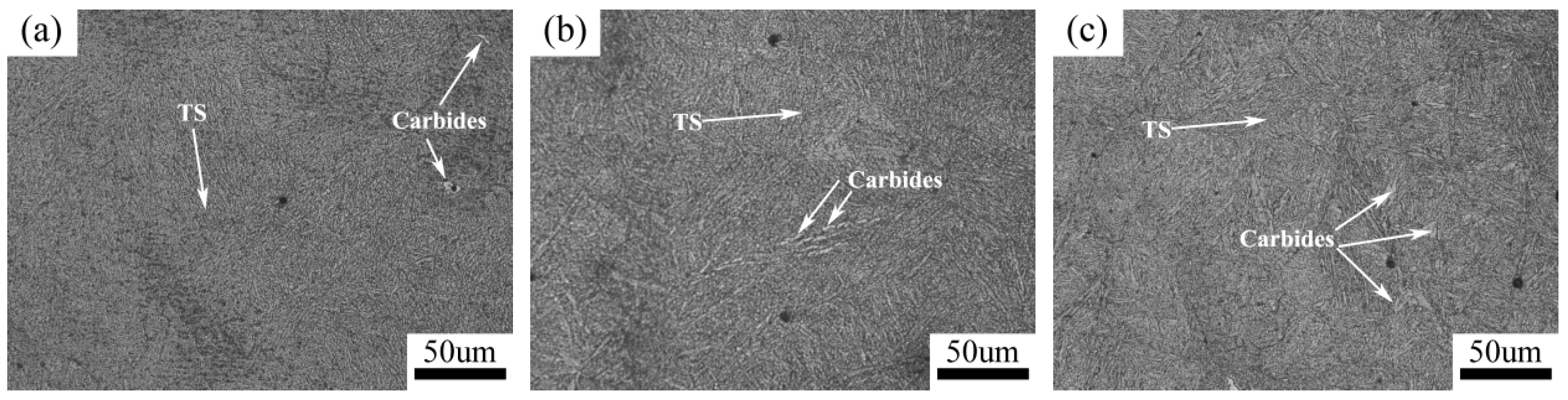
Figure 14.
Microstructure of tempering zone at different heat inputs. (a) 4.2 kJ/cm, (b) 5.4 kJ/cm, and (c) 6.6 kJ/cm.
Table 1.
Chemical composition of 5Cr5MoV die steel (wt.%).
| Element | C | Si | Mn | Cr | Mo | V | S | P | Fe |
|---|
| 5Cr5MoV | 0.60 | 1.03 | 0.84 | 5.26 | 0.76 | 0.64 | 0.013 | 0.028 | Bal. |
Table 2.
Welding parameters for the repair process of 5Cr5MoV die steel.
| Sample Notation | Diameter of Electrode (mm) | Welding Current (A) | Welding Voltage (V) | Welding Speed (cm·min−1) | Heat Input (kJ·cm−1) |
|---|
| SL | 3.2 | 70 | 25 | 20 | 4.2 |
| SM | 3.2 | 90 | 25 | 20 | 5.4 |
| SH | 3.2 | 110 | 25 | 20 | 6.6 |
Table 3.
Chemical compositions of the covered electrode (wt.%).
| Element | C | Si | Mn | Cr | Mo | S | P | Fe |
|---|
| S-700B.B | 0.56 | 1.26 | 1.67 | 4.06 | 1.84 | 0.011 | 0.029 | Bal. |
Table 4.
Mechanical properties of samples from the tensile tests.
| Group | Ultimate Strength (MPa) | Elongation (%) |
|---|
| A | B | C | A | B | C |
|---|
| 4.2 kJ/cm | 501 | 518 | 730 | 1.21 | 1.06 | 1.83 |
| 5.4 kJ/cm | 522 | 525 | 665 | 1.08 | 1.07 | 1.54 |
| 6.6 kJ/cm | 548 | 590 | 729 | 1.10 | 1.17 | 1.65 |
© 2018 by the authors. Licensee MDPI, Basel, Switzerland. This article is an open access article distributed under the terms and conditions of the Creative Commons Attribution (CC BY) license (http://creativecommons.org/licenses/by/4.0/).


