Article

Sustainable Hydrometallurgical Recovery of Valuable Elements from Spent Nickel–Metal Hydride HEV Batteries

Department of Chemical Engineering, KTH Royal Institute of Technology, Stockholm 100 44, Sweden
*
Author to whom correspondence should be addressed.
Metals 2018, 8(12), 1062; https://doi.org/10.3390/met8121062
Submission received: 8 November 2018 / Revised: 4 December 2018 / Accepted: 6 December 2018 / Published: 14 December 2018

Abstract

:
In the present study, the recovery of valuable metals from a Panasonic Prismatic Module 6.5 Ah NiMH 7.2 V plastic casing hybrid electric vehicle (HEV) battery has been investigated, processing the anode and cathode electrodes separately. The study focuses on the recovery of the most valuable compounds, i.e., nickel, cobalt and rare earth elements (REE). Most of the REE (La, Ce, Nd, Pr and Y) were found in the anode active material (33% by mass), whereas only a small amount of Y was found in the cathode material. The electrodes were leached in sulfuric acid and in hydrochloric acid, respectively, under different conditions. The results indicated that the dissolution kinetics of nickel could be slow as a result of slow dissolution kinetics of nickel oxide. At leaching in sulfuric acid, light rare earths were found to reprecipitate increasingly with increasing temperature and sulfuric acid concentration. Following the leaching, the separation of REE from the sulfuric acid leach liquor by precipitation as NaREE (SO4)2·H2O and from the hydrochloric acid leach solution as REE2(C2O4)3·xH2O were investigated. By adding sodium ions, the REE could be precipitated as NaREE (SO4)2·H2O with little loss of Co and Ni. By using a stoichiometric oxalic acid excess of 300%, the REE could be precipitated as oxalates while avoiding nickel and cobalt co-precipitation. By using nanofiltration it was possible to recover hydrochloric acid after leaching the anode material.

1. Introduction

It is well known that the hybrid electric vehicle (HEV) is becoming more common due to economic and environmental reasons. Batteries are widely used in HEVs such as automobiles or larger trucks for transportation purposes. The most common type of battery in these vehicles is nickel metal hydride (NiMH), mainly due to Toyota’s decision to use them in their popular Prius. More than two million hybrid cars worldwide are running with NiMH batteries, such as the Prius, Lexus (Toyota), Civic, Insight (Honda), and Fusion (Ford). Panasonic manufactures HEV prismatic NiMH batteries that have been used by Toyota and GM (among others), while Sanyo manufactures HEV cylindrical cell NiMH batteries, which have been used by Honda and Ford.
Considering the limited life span of these batteries and their valuable components such as nickel, cobalt, and rare earth elements (REE), it is very important to be able to recycle battery materials. The REE have been declared as high supply risk materials by the European Commission [1,2]. Guyonnet et al. (2015) showed an imbalance between the upstream and downstream parts of the value chain for Nd in NiMH battery applications within Europe in 2010, where Europe largely relied on the import of batteries [3]. The results underlined the potential of recycling the batteries in Europe, considering the large amounts of in-use stocks and spent batteries (waste). Rare earth elements have a vital role in many technological advances, including green and sustainable applications. Praseodymium, neodymium and dysprosium drive the demand for light and heavy REE and their demand is expected to remain high in coming years due to their use in magnets [3,4,5]. The recovery of REE from magnets has been investigated, e.g., using organic acids for leaching and applying solvent extraction to recover the REE from the leach liquor [6]. Spent NiMH batteries contain about 8–10% REEs by weight, including praseodymium and neodymium [7]. After magnets, these batteries are the largest alternative REE source available for recycling [8,9].
There are many scientific and industry cooperative studies for the urban mining and recycling of batteries at different scales [8,10,11,12,13,14]. This address both the physical separation techniques based on gravity, magnetic, and electrostatic methods and subsequent costlier hydrometallurgical and/or pyrometallurgical processes. Pyrometallurgical processes are often simple but the value of the resulting alloys is not particularly high and the REE ends up in a slag [12,15]. Umicore and Rhodia have developed a process to recover metals from NiMH batteries by pyrometallurgical processing. The end product is an alloy containing Ni, Co, Cu, Fe and a slag containing the REE; the REE can be recovered from the slag and purified by hydrometallurgical processing [15]. Benefits of hydrometallurgical processes compared to alternative pyrometallurgical processes are that a full recovery of the metal content with high purity can be achieved, they require less energy, and they generate less waste water and air emissions. Pyro/hydro hybrid methods have been studied as a complement to established techniques [16]. Many hydrometallurgical processes start with an almost complete leaching of the batteries [12,17,18,19,20,21,22,23,24]. For example, leaching by sulfuric acid and hydrochloric acid has been investigated in different studies [17,18,20,21,22,25,26,27]. The rare earth elements present in metallic form are oxidized into trivalent ions in contact with hydrochloric acid and sulfuric acid according to the following reactions:
REE (s) + 3H2SO4 + 1.5O2 (g) = REE+3 + 3SO4−2 + 3H2O
REE (s) + 3HCl = REE+3 + 3Cl- + 3/2H2 (g)
Ni, Co, and Mn can be assumed to be divalent and Fe, Al and the REEs can be assumed to be trivalent in the acid leach liquor. Larsson [22] studied the minimum required amount of different types of acid to completely dissolve the electrode materials. In this study the temperature was kept constant and acid was dosed during the leaching to also keep the pH constant. For further processing, precipitation and solvent extraction can be used to recover Co, Ni, and the rare earth elements [17,25,27,28,29,30,31,32,33]. The recovery of nickel and cobalt has an important role for the economics of the recycling processes. There are many proposed processes for the recovery of nickel and cobalt ions from different leach liquors in the literature [34].
The present project aims at developing an environmentally and economically sustainable hydrometallurgical process for recovery of the valuable elements from spent NiMH HEV batteries. The focus is on investigating new pathways where acid can be recycled, undesired side products are avoided, and separation systems are designed for maximum recovery and minimum energy usage. In the present study, the cathode and anode materials have been properly characterized by powder XRD and SEM–EDS. Two different leaching routes have been studied and compared, using either HCl or H2SO4 for dissolving the active anode material. The main objective behind the leaching stage is to obtain maximum recovery of the rare earth elements, nickel, and cobalt. The two electrode materials are dissolved separately. The leaching of individual elements is recorded with time and the optimum conditions for leaching are determined. In previous studies, the leaching outcomes under similar conditions have been reported [12,17,23,31], but the fate of the elements as a function of time is seldom reported for leaching of NiMH HEV batteries nor for the leaching of anode and cathode materials separately. In the present study, the separation of REE from the leach liquors by precipitation and an integrated recovery of acid by nanofiltration have been investigated and assessed. Nanofiltration can be applied to recycle used waste pickling acid [35], to separate REE from acid mine drainage and to deal with environmentally problematic wastes [36], to recover nickel [37] and to separate Nd from waste water [38].

2. Experimental Procedures

2.1. Mechanical Separation

A Panasonic Prismatic NiMH HEV battery with 6.5 Ah and 7.2 V was used in the experiments. The modules had plastic casings and were discharged below 4 V. First the plastic case was carefully cut open and then the cells were removed. There were six cells and each was covered with pink polymeric sheets to keep them apart. Each cell was washed with deionized water to remove the residual electrolyte and then air-dried. Each cell consisted of 12 cathode and 13 anode plates. The active material of the anode was effortlessly scraped off from the supporting mesh, while the cathode active material was nearly impossible to completely separate from its mesh. Thus, the cathode active material was mixed with the cathode mesh and will hereafter be referred to as the cathode material.

2.2. Material Characterization

Each module (1050 g) consisted of six separate cells (about 150 g each), a plastic casing, metal connections, and electrolyte (KOH). Characterizations of the anode and cathode materials, their supporting mesh, leach residues, leach liquors, and precipitates were done by ICP-OES (Thermo Fisher iCAP 7000), SEM EDS (Hitachi S-3700N) and powder XRD (Brukar D8 Discover) employing a Cu K-alpha source with a step size of 0.01 degree. The cathode electrode was soaked in dilute nitric acid solution to wash away the active material so the examination of the supporting mesh by SEM would be possible. Total dissolution of the separate active materials was performed in 8 mol/L nitric acid using a solid to liquid ratio of 1/200 (g/mL) at 90 °C for 6 h. This procedure was repeated 3 times and mean values are reported.

2.3. Acid Leaching

The leaching experiments were performed in partly sealed Erlenmeyer glass flasks placed on magnetic stirring plates in a thermostatic water bath. A condenser unit was used to preserve atmospheric pressure. Suspensions were continuously stirred at 500 rpm using Teflon-coated stirring bars, which was sufficient to fully disperse and suspend the solid material in the solutions. Deionized water and acids of analytical grade (PA) were used in the experiments.
The anode and cathode materials were separately dissolved in H2SO4 or HCl of different concentration at atmospheric pressure and at different temperatures (see Table 1). The aim was to study the rate of dissolution of the different materials and the equilibrium compositions under different conditions. The acid concentration ranges were selected based on the estimated acid consumption during leaching.
In a full-scale process one option could be to mechanically grind the anode active material together with its nickel-covered stainless-steel mesh, even though the anode active material separates easily from the mesh. To investigate this processing condition, in separate experiments the anode active material was leached together with the mesh (see Table 2). The mass ratio of the anode active material to mesh was chosen in accordance to the composition of the battery cells.
The dissolution was recorded as a function of time by sampling using syringes. The solid material was immediately separated from the liquid phase using syringe filters (0.2 µm). The liquid samples were then diluted 100 times and stored in high density polyethylene (HDPE) bottles before ICP-OES analysis to determine the REE concentration and other minor elements such as zinc, aluminum, iron, and potassium. Some samples were further diluted to appropriate concentrations for ICP-OES measurements of elements present at high concentration (Ni, La). When the dissolution process had ceased, pH was measured using an Orion ROSS electrode, which was calibrated by Thermo Fisher Scientific standard solutions at pH 2, 4, and 7. The leach residues were separated from the leach liquor by using filter paper (0.2 µm) and the leach liquor was stored in plastic bottles prior to further processing. The leach residue was washed with dilute acidic water (5 vol% with same type of acid used in leaching).

2.4. Acid Recovery by Nanofiltration

The application of nanofiltration to recover part of the acid from the hydrochloric acid leach liquor was investigated. The aim is to recycle back the hydrochloric acid to the leaching stage. The purpose of the experiments was to investigate the capacity of the chosen membrane in terms of flux (permeate flow rate) and retention of the metal ions.
First anode and cathode material were leached together using 15 L of 2 mol/L hydrochloric acid and a solid to liquid ratio of 1/200 (Sample L1). In addition, 20L of synthetic leach liquor containing Ni, Co and Mn was prepared (Sample L2) with a composition chosen to resemble the leach liquor composition obtained under optimal hydrochloric acid leaching conditions of 2 mol/L hydrochloric acid and a solid to liquid ratio of 1/20. The compositions of the resulting leach liquors are presented in Table 3.
The nanofiltration experiments performed are presented in Table 4. The metals will be retained in the reject stream while acid with low concentration of metal ions is recovered in the permeate stream. The membrane used was a pH-stable spiral-wound nanofiltration membrane (MPS-34 2540 A2X, Koch) with an effective membrane area of 1.6 m2 and a typical operating pressure of 15–35 bar. The small pilot scale setup used consists of the membrane unit, two holding tanks and a pump. Manometers are installed before and after the nanofiltration module to record the pressure and a valve, placed on the outlet side of the membrane, was used to adjust the operating pressure. Before the experiment, the membrane unit was washed with P3 Ultrasil ca. 1%, at 40 °C for 30 min and then rinsed 3 times. The water flow during the wash test was 52 L/h at 20 bar and 25 °C. The leach liquor was first repeatedly circulated through the nanofiltration unit with full recycle of both the retentate and permeate streams for 30 min until a steady flow was obtained, recorded as the initial flux. Then the permeate stream was separated while the retentate stream was re-circulated until a volume reduction of 50% was reached (i.e., 7.5 L of permeate in experiment N1). This can be expressed in terms of a volume reduction factor (VRF):
V R F = I n i t i a l   v o l u m e   o f   l e a c h   l i q u o r V o l u m e   o f   r e t e n t a t e   a t   t i m e   t
Initially, when all permeate and retentate is re-circulated the VRF equals 1 (time 0). When half of the initial leachate volume can be found in the permeate tank the VRF equals 2. Under the applied conditions, with a flow rate of 26.4 L/h, this occurs after about 30 min.
Samples of 100 mL were collected from both the retentate and permeate streams for VRF = 1 and VRF = 2. The samples were diluted by 5% nitric acid and the total concentration of Ni, Co, La, Ce, Nd, Pr, Y, Mn, Al and Zn were measured by ICP-OES. The residual acidity of the permeate was determined by titration.
The permeate from experiment N2 was collected and then used to leach anode material at 25 °C, presented as experiment 10A in Table 1.

2.5. Separation of Rare Earth Elements by Precipitation

The REE were separated from the sulfuric anode leach liquors by precipitation as sodium REE sulfate monohydrate through addition of sodium hydroxide. The REE was separated from the hydrochloric acid anode leach liquors by precipitation as oxalates by the addition of oxalic acid. The experiments performed are presented in Table 5.
The precipitation experiments were performed in sealed Erlenmeyer glass flasks placed in a water bath with controlled temperature (25 °C). The solutions/suspensions were constantly stirred at 500 rpm using a magnetic stir bar. Samples were extracted by a syringe, the first 15 min after reagent addition. The apparent pH was also measured. The solid phase was separated from the liquid phase using syringe filters (0.2 µm) for sampling purposes. The elemental composition of the liquid phase was determined by ICP-OES after dilution of the samples, while the solid phase was filtered off using filter paper (0.2 µm), washed with ethanol, and dried at 80 °C for 12 h. The solid samples were then stored at room temperature prior to analysis by powder-XRD and SEM–EDS.
For the oxalic acid experiments, 10 g of oxalic acid (Sigma Aldrich, 99.0% purity) was dissolved in 100 mL of water and this solution was added to the leach liquor. The theoretically needed amount to precipitate all REE, without the presence of other complexing cations, was calculated and the amount of added oxalic acid is reported as percentage excess of this amount. Experiment P5 was left for 24 h with constant stirring and at a temperature of 25 °C before filtering off the precipitates. In experiment P6, NaOH (Sigma Aldrich, 4 mol/L) was added at constant amount within certain time intervals under constant stirring. The pH was noted before and after each sampling. In evaluating the results, the measured ion concentrations were corrected for the dilution of the solution due to the addition of oxalic acid or sodium hydroxide.

3. Results and Discussion

3.1. Material Characterization

The individual cathode plates weighed 4.1 g and the anode plates with support mesh weighed 3.9 g. The ratio per gram for anode active material to its mesh is 0.28.
The cathode material was completely dissolved but the anode dissolution resulted in a small amount of solid leach residue. The chemical composition of the materials is given in Table 6. The mass of the measured elements present in the cathode material amounts to 89% of the total mass, and the rest of the material mainly consists of hydroxide ions.
The rare earths Ce, La, Nd, Pr and Y were identified. Most of the rare earth elements are concentrated in the anode active material. Lanthanum is present in the highest concentration (located in the anode). Yttrium is found in both the cathode and anode materials. Nickel is the element with the highest concentration in both materials and has high economic value to recover and recycle back into the market. The cobalt content in both materials is also high enough to be considered as recoverable from an economic point of view.
The rare earth alloy Ce0.47 La0.34 Nd0.14 Pr0.05 Ni3.56 Co0.75 Al0.29 Mn0.4 (01-076-7719) and the LaNi5 crystal structure were identified in the anode material by powder-XRD. Pure rare earth elements or other metals, such as Fe, Zn, and Al, could not be detected. These elements can be assumed to exist in the crystal structure of the nickel hydroxide, and rare earth’s alloy as substitute or interstitial atoms. The cathode material consists of nickel hydroxide with a substitution of cobalt appearing as nickel-cobalt hydroxide and metallic nickel and cobalt. The metallic nickel and cobalt may come from the supporting mesh of the cathode plate. No yttrium related peaks were found.
The strongest peaks belong to LaNi5 and nickel–cobalt hydroxide in the anode and cathode respectively. These results are consistent with the characterization of the same battery [22] and with other studies on the characterization of similar materials [39,40].
The cathode material consists of a nickel supporting mesh and nickel hydroxide, as can be seen in Figure 1. The skeleton-like structure on the left-hand side in Figure 1 was visible after washing off the active material by dilute nitric acid. The supporting mesh is made entirely of pure nickel, as confirmed by EDS. The active material covering the mesh is shown on the right-hand side in Figure 1. It consists of spherical (10–20 µm) nickel hydroxide particles. The material surrounding the spheres was identified as the same nickel hydroxide material as the spheres were made of. The results are consistent with the XRD results, which showed large nickel hydroxide peaks with possible cobalt substitution. Nickel and cobalt tend to substitute for each other in different structures due to their similar ionic radii. The EDS analysis results also identified yttrium in the cathode active material and other minor elements such as zinc, aluminum and potassium.
The supporting mesh in the anode is made from nickel-coated stainless steel. EDS results showed that the rare earth elements (Ce, Nd, Pr, and Y) are found together with much higher amounts of nickel, indicating that the REE are hosted in the LaNi5 alloys’ crystal structure. Yttrium was not one of the rare earth elements found with nickel within LaNi5 particles. Yttrium was found within relatively smaller-sized particles, which could be yttrium oxide.

3.2. Acid Leaching

The final measured pH values of the leach solutions were in the range of −2.2 to −2.4. In all of the leaching experiments (exp.1–10), approximately 4–7% of the initial weight remained undissolved as leach residue. The amount of leach residue decreased slightly with increasing acid concentration and temperature. In the low temperature cathode material experiments (exp. 1, 2, 5 and 6), there were negligible quantities of leach residue. No leach residue was left in the other experiments.

3.2.1. Anode Sulfuric Acid Leaching

The increase in concentration of the REE (La, Ce, Pr, Nd, and Y), Co, and Ni in the aqueous phase is presented as a function of time for experiments 1A and 2A (see Table 1) in Figure 2 and Figure 3 below. The anode material is slowly leached in 1 mol/L sulfuric acid solution at 25 °C as shown in Figure 2. Recovery percentages are calculated based on concentrations of elements given in Figure 2 and Figure 3 and data from the total dissolution. After 240 min the recovery of nickel is 72.5% by mass in experiment 1A. In experiment 2A, leaching with 2 mol/L, 69.4% recovery of Ni was reached. A 98% recovery of nickel is obtained after 240 min by using the same initial acid concentration but a higher temperature in experiment 3. It is possible that the recovery is lower at lower temperature due to the etch kinetics of nickel. When using oxidizing acids (such as H2SO4) nickel metal may passivate and remain in the solid phase, i.e., form a surface layer of nickel oxide/hydroxide that is not easily dissolved and that prevents further dissolution of the alloy. The formation of a nickel compound, possibly nickel oxide, could also occur before the leaching. The SEM–EDS study partly confirms the theory since nickel oxide traces are found in the leach residue of the low temperature and low acid concentrated acid leaching experiments, which does not exist in the initial XRD patterns. Nickel oxide/hydroxide has a low dissolution rate in sulfuric acid and the rate is increased by an increase in temperature. However, the results reported in literature for Ni metal passivation are not directly comparable to the present alloy. Acid concentration and temperature are important variables when considering corrosion of alloys. In addition, the presence of impurities can substantially affect the corrosion rate.
The leaching recovery of rare earth elements and cobalt are high even at low temperatures (93% for Ce, 95% for La, 95.4 % for Nd, 94.3% for Pr, 91.1% for Y, and 94% for Co by mass in 1 mol/L H2SO4 at 25 °C after 240 min, experiment 1A). The small decrease in the rare earth concentration with time in 2 mol/L H2SO4 at 25 °C, seen in Figure 3, could be due to precipitation of rare earth sulfates, but there was no visible precipitation in the leach solution in this experiment. There are many REE sulfate hydrates and also polymorphs reported in the literature, however, at 25 °C the binary nonahydrates (La and Ce) or octahydrates (heavier REE) are expected to be the most stable phases in saturated water solution [41,42]. The solubility of rare earth sulfates (REE2(SO4)3·xH2O) decreases as the temperature increases and as the sulfuric acid concentration increases [43,44]. At higher temperatures, the decrease in REE concentration with time is more obvious. The same phenomenon was observed for an initial sulfuric acid concentration of 4 mol/L and at 90 °C (exp. 4) where the precipitation could be clearly seen by the naked eye during the experiment. The solid material was collected at the end of the experiment. SEM–EDS measurements showed that it consisted of leach residue of the anode material and indicated the presence of REE2(SO4)3·xH2O.
The results from leaching the active anode material together with the nickel-coated stainless-steel mesh is presented in Figure 4. As can be seen in Figure 4, the recovery of Ni, Co and REE are lower than in the experiments using only the active anode materials. The Fe concentration in the final leach liquor after leaching of the active anode material was 46 mg/L in experiment 2A. When leaching the active anode material together with the mesh, the concentration of iron in the final leach liquor increased up to 1.6 g/L in experiment C1. The decreased leaching recovery of nickel, cobalt and REE is caused by the consumption of acid to leach the supporting mesh.
A SEM image of the leach residue and EDS results measured as a point analysis are shown in Figure 5 and Table 7, respectively. The rare earth sulfate precipitates have a smaller particle size than the anode leach residue. The phase contains a mixture of the light REE (La, Ce, Pr, Nd) together with some nickel and sulfur. The atomic % ratio of REE to S is 0.8, which is similar to REE2(SO4)3·xH2O (0.7). The heavy REE, yttrium, was not found to precipitate as sulfate hydrate with the rest of the REE. That could be the result of heavier rare earth elements creating aqueous complexes in the solution to a larger extent compared to light rare earth elements due to increased strength of cation-anion interactions with the decrease in the ionic radii in the lanthanide series [45]. In the light of this information, it is clear that high concentration of sulfuric acid cannot be used in the leaching stage; otherwise, the loss of rare earth elements and nickel as precipitates during the leaching stage would affect the economics of the process.

3.2.2. Anode Hydrochloric Acid Leaching

The leaching of the anode active material at 25 °C with an initial hydrochloric acid concentration of 1 mol/L (exp. 5A, see Table 1), is shown in Figure 6. Recovery percentages are calculated based on concentrations of elements given in Figure 6 and data from total dissolution. The mass recovery of nickel and cobalt after 240 min is 44.2% and 80.7%, respectively. The recovery of the rare earth elements is 99% by mass after 240 min. The rare earth elements are almost completely dissolved within 60 min at low concentration of hydrochloric acid (1 mol/L) and at low temperature (25 °C), while the recovery of Ni is poor.
At higher temperature (90 °C) in experiments 7–9A, the recovery of nickel is improved. After 1 h, nickel has reached 99% recovery and Co has reached 90%, whereas the rare earth element dissolution is still up to 99% by mass in experiment 7A. With continued leaching. however, nickel begins to precipitate (presumably as a nickel chloride phase) and the recovery decreases to 95%, 94%, and 87% for an initial concentration of 2 mol/L, 4 mol/L and 8 mol/L of HCl, respectively. The same decrease in concentration by time could be observed for the rare earth elements. However, the precipitates dissolve again at the end of the 4-h experiments. The best conditions for HCl leaching for recovery of the valuable elements in the anode material, was an initial concentration of 2 mol/L of HCl and leaching for 1 h at 90 °C (experiment 7A).
Leaching the active anode material together with the nickel coated stainless steel mesh (4C) gave lower recoveries of Ni, Co and REE compared to the experiments with only active anode material (6A). The Fe concentration in the final leach liquor after leaching of the active anode material was 43 mg/L in experiment 6A. When leaching the active anode material together with the mesh the concentration of iron in the final leach liquor increased up to 4 g/L in experiment C4. Less iron is leached using HCl compared to using H2SO4 of corresponding initial molarity. Similarly, the chromium concentration is 5 mg/L in experiment 6A, but when leached together with the mesh it became 129 mg/L in experiment C4, which was expected since the characterization of anodic mesh revealed that it was stainless steel. The decreased leaching recovery of nickel, cobalt and REE is caused by the consumption of acid to leach the supporting mesh.

3.2.3. Cathode Sulfuric Acid Leaching

The cathode consists of nickel hydroxide with substitutions of cobalt, as reported above, and presumably of zinc [24,39] and Y2O3 and nickel metal. At 25 °C in 2 mol/L H2SO4, the recovery of nickel was 38.7%, measured after 15 min and with no measurable increase in concentration for up to 240 min leaching time (exp. 2B, see Table 1). However, at a higher temperature (exp. 3B) the recovery reaches up to 99.9% after 4 h. The cobalt and yttrium solid phases leach quickly and with high recovery rates, even at low sulfuric acid concentrations and low temperatures. Their recoveries were 87.9% and 100%, respectively, at 25 °C and 1 mol/L initial sulfuric acid concentration after 240 min in experiment 1B. This shows that the spherical nickel hydroxide particles dissolve while the nickel metal part of the cathode material remains largely as a solid phase at lower temperature. Even at high concentrations of sulfuric acid (4 mol/L), yttrium did not precipitate.

3.2.4. Cathode Hydrochloric Acid Leaching

The recovery of Ni in experiments 5B and 6B after 4 h leaching time at 25 °C by mass was 41.3% and 43.8% using an initial concentration of 1 mol/L and 2 mol/L of HCl, respectively (see Figure 7). At higher temperature (90 °C), 99.9% recovery of nickel was obtained after 4 h using an initial concentration of 2 mol/L of HCl. By using an initial concentration of 4 mol/L and 8 mol/L of HCl, the maximum recovery was reached after only 15 min in experiments 8B and 9B.
The mass recovery of yttrium is 100% after 15 min of leaching at 25 °C using an initial concentration of 1 mol/L. This suggests the possibility of partial selective leaching of yttrium at 25 °C using an initial concentration of 1 mol/L, as only 41.3% of the nickel and 83.6% of cobalt is leached in the first 15 min. The remaining solid phase is mainly pure metallic nickel.

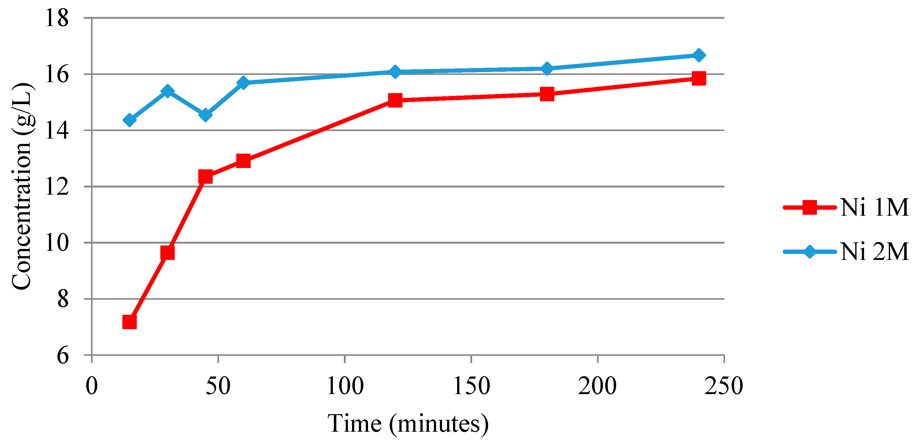
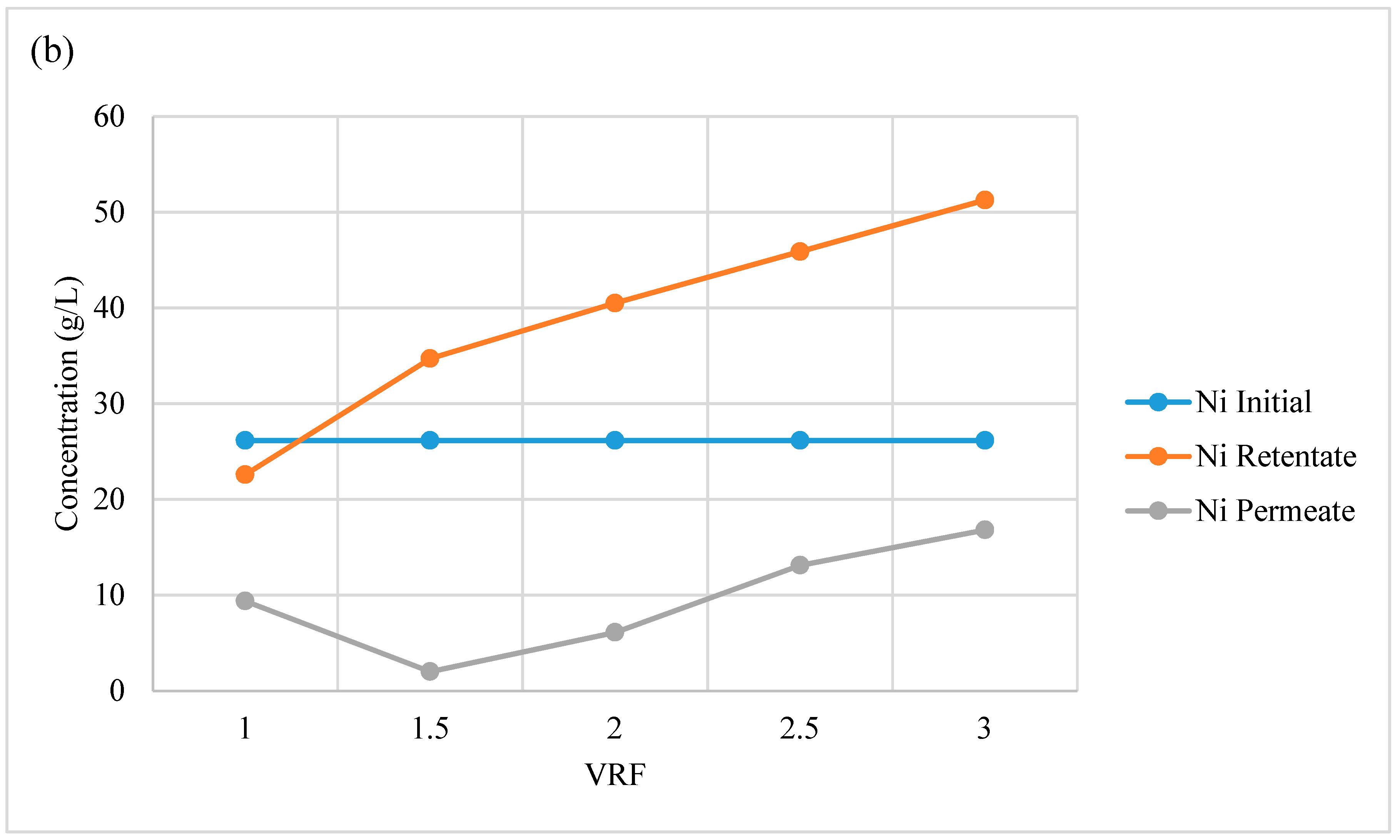
3.2.5. Acid Recovery via Nanofiltration

The conditioning of the membrane, by recirculating the retentate and permeate for 30 min prior to starting the experiments, did not show any signs of concentration buildup causing membrane scaling.
The measured concentrations of the main metal ions present in the leach liquors at the beginning of the experiment (VRF = 1) and after a 50% volume reduction (VRF = 2) are presented in Table 8. The test was conducted at 20 bar and the flux at VRF2 was 18 L/(m2, h).
The results show that there is no accumulation of elements in the system, e.g., due to precipitation. The permeate stream contains low concentration of metal ions, both at the beginning of the experiment (VRF = 1) and after a 50% volume reduction (VRF = 2). The concentrations of metal ions in the permeate stream are higher after a 50% volume reduction. This is expected since the feed liquor at this point contains about double the concentration of metal ions. The pH of the permeate at a VRF of 1 and 2 was measured to be −0.19 and −0.17, respectively, which is very close to the initial pH of the leach liquors. The free hydrochloric acid concentration of the permeate after 50% volume reduction was calculated to be 1.7 mol/L, which is very close to the initial acid concentration used in the leaching stage (2 mol/L) and the existing metal ion concentration is very low, thus the permeate stream is suitable for recycling to the leaching stage.
The results with respect to the concentration of metal ions in the feed, retentate and permeate from the experiment with synthetic leach liquor (N2) are presented in Figure 8. The results show that when using approximately six times higher initial metal ion concentrations in experiment N2 than in experiment N1, the metal ion concentrations in the permeate are higher than in experiment N1, but the metal ion concentrations are still low enough to be able to re-cycle the permeate stream to the leaching stage. However, the high metal ion concentration in N2 resulted in a higher pressure drop. The flux at VRF2 was approximately 2 L/(m2, h) with a pressure of 25 bar. The permeate after VFR = 3 was used to leach the anode active material under optimum conditions (experiment 10A). The results show that the leaching recovery after 240 min of leaching was 99% for the REE, 94.3% for Ni and 93% for Co when compared with using fresh 2 mol/L HCl under corresponding conditions (experiment 6A). In addition, no precipitation could be seen during the nanofiltration experiment.

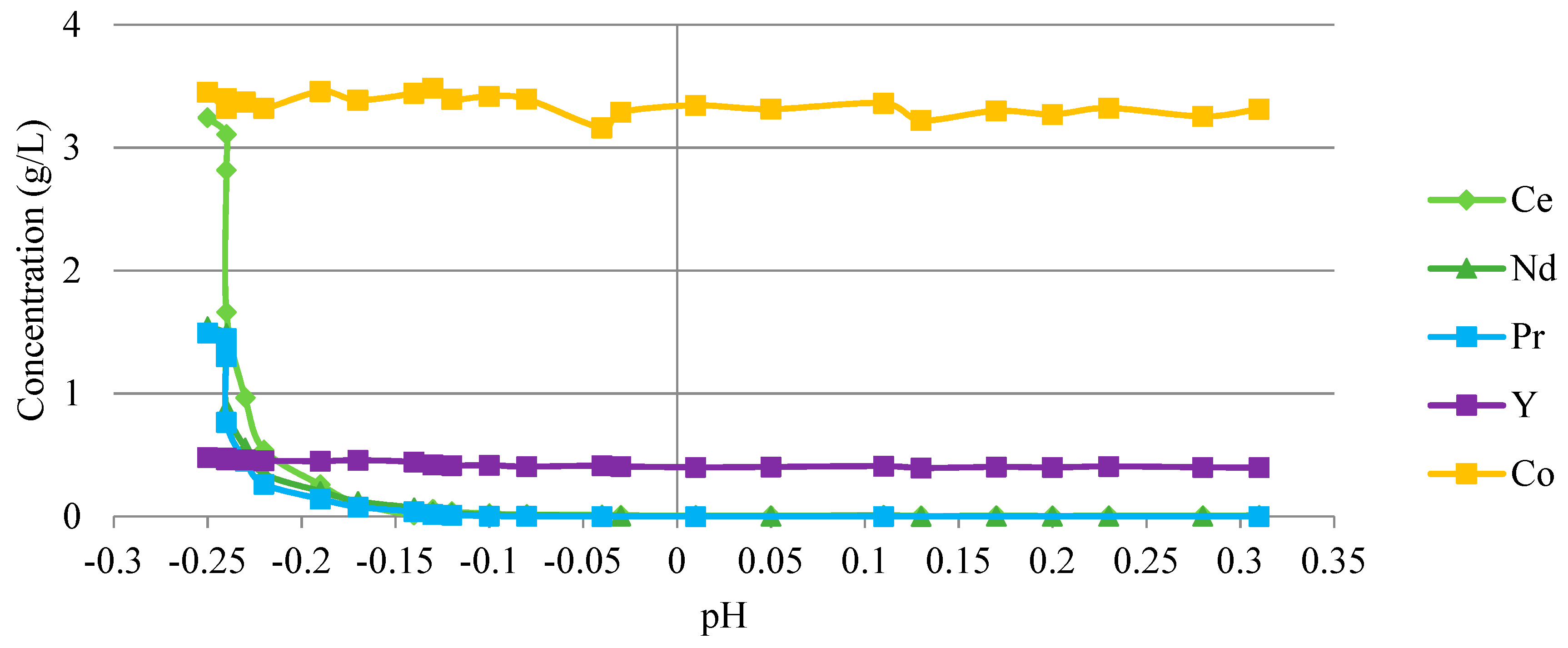
3.2.6. Separation of Rare Earth Elements by Precipitation

After leaching using an initial concentration of 2 mol/L of H2SO4 at 90 °C, the liquor was used for the first series of precipitation experiments. In experiment P6, the REE were separated by precipitation as NaREE(SO4)2·H2O by adding NaOH to the leach liquor. All the light rare earth elements were found in the solid phase at around pH −0.1 and 0.7 mol/L sodium ion concentrations; see Figure 9. The heavy REE, Y, however, present at comparably low concentration, does not precipitate. There was no significant nickel and cobalt loss occurring during the precipitation of rare earth elements.
In the second series of experiments, hydrochloric acid leach liquor was used (from experiment 8A, see Table 1). The results show that about 95% by mass of the rare earth elements precipitate as REE2(C2O4)3·nH2O at a 300% excess addition of oxalic acid, see Figure 10. This value increases up to 100% at 600% excess oxalic acid addition in experiment P1–P5. At higher concentrations of oxalic acid, all of the nickel precipitates as well. The optimum point seems to be 300% excess addition of the reagent. The relatively high dose of oxalic acid needed to precipitate the REE is due to the high concentration of other metal ions in the solution forming complexes with the oxalate ions. The purities of the REE oxalate precipitates are 99.9% (100% excess), 90.1% (300% excess) and 39.1% (600% excess). Based on a mass balance, the overall recovery of REE after leaching with sulfuric acid (2 mol/L, 25 °C) was calculated to be 90%. The overall recovery of REE after leaching with hydrochloric acid (2 mol/L, 90 °C) was calculated to be 92%.

4. Conclusions

In the anode, the rare earth elements were found to be in in the form of LaNi5 and Ce0.47 La0.34 Nd0.14 Pr0.05 Ni3.56 Co0.75 Al0.29Mn0.4 phases. In the cathode active material, the nickel hydroxide was the main phase with the existence of metallic cobalt and substitutional cobalt in the nickel hydroxide together with yttrium (III) oxide. The supporting mesh of the cathode was made of metallic nickel. The chemical composition showed that nickel is the dominant metal in both of the electrode active materials. The cathode material’s metal composition was 75.5% Ni, 4.7% Co, 0.7% Y, and 3.5% Zn, with smaller amounts of Fe, Al, and K.
It was found that the acid leaching of nickel is kinetically limited at 25 °C under the conditions applied and higher temperature is required to achieve an industrially reasonable leaching rate. The best REE, Ni, and Co recoveries were obtained when using an initial concentration of 2 mol/L of hydrochloric or sulfuric acid and high temperature (90 °C). The recoveries of rare earth elements in all experiments done under these conditions were 95% or more, except when leaching the anode material with sulfuric acid. In that specific experiment, the recoveries were reduced to 60–80% due to sulfate precipitation during the leaching. For leaching the anode material with sulfuric acid, the best conditions for rare earth elements recovery were using an initial acid concentration of 2 mol/L at 25 °C. When the anode active material is leached with its supporting mesh, the anode and cathode active materials were dissolved, while the mesh was partially dissolved leading to a high concentration of Fe and Cr in the leach liquor—around 4mg/L and 129 mg/L, respectively, depending on given conditions.
By using nanofiltration it was possible to recover hydrochloric acid after leaching the anode material. No precipitation was observed during the nanofiltration operations. The acid can be re-used in leaching of the anode materials. However, the flux was low (2 L/(m2, h)), even when applying a pressure of 25 bar.
By addition of NaOH, the light rare earth elements precipitated as NaREE(SO4)2·H2O around pH −0.1 and 0.7 mol/L sodium ion concentration with no significant loss of Co and Ni. However, the heavy REE, Y, present at a concentration of 0.4 g/L, did not precipitate under these conditions. For the precipitation of REE2(C2O4)3·nH2O, the optimum conditions for precipitating all rare earths while avoiding nickel or cobalt co-precipitation was obtained using a stoichiometric oxalic acid excess of 300%. The overall recovery of REE after leaching with sulfuric acid (2 mol/L, 25 °C) and precipitation of NaREE(SO4)2·H2O was 90%. The overall recovery of REE after leaching with hydrochloric acid (2 mol/L, 90 °C) and precipitation of REE oxalates was 92%.

Author Contributions

Conceptualization, K.K. and K.M.F.; Methodology, K.K.; Validation, K.K.; Investigation, K.K.; Resources, K.K. and M.A.; Writing-Original Draft Preparation, K.K.; Writing-Review & Editing, K.K., M.A., Å.C.R. and K.M.F.; Supervision, K.M.F. and Å.C.R.; Project Administration, K.M.F.; Funding Acquisition, K.M.F.

Funding

This research was funded by Swedish Energy Agency (Energimyndigheten) with the project number 37724-1.

Acknowledgments

The authors would like to acknowledge the Swedish Energy Agency for funding the project (project nr 37724-1) and Chalmers University of Technology, Department of Chemistry and Chemical Engineering for supplying the battery modules and Swedish Environmental Research Institute (IVL) for instrumentation and expertise in connection to conducting the nanofiltration experiments. Part of the work was also supported by the Swedish Foundation for Strategic Research SSF with the grant number of IRT 11-0026.

Conflicts of Interest

The authors declare no conflict of interest. The funders had no role in the design of the study; in the collection, analyses, or interpretation of data; in the writing of the manuscript, and in the decision to publish the results.

References

  1. European Commission. Critical Raw Materials for the EU, in Report of the Ad-Hoc Working Group on Defining Critical Raw Materials; European Commission: Brussels, Belgium, 2010. [Google Scholar]
  2. Moss, R.; Tzimas, W.P.; Arendorf, J.; Tercero Espinoza, L. Critical Metals in the Path towards the Decarbonisation of the EU Energy Sector: Assessing Rare Metals as Supply Chain Bottlenecks in Low-Carbon Energy Technologies; Technical Report, JRC Scientific and Technical Reports; European Commission: Brussels, Belgium, 2013. [Google Scholar]
  3. Guyonnet, D.; Planchon, M.; Rollat, A.; Escalon, V.; Tuduri, J.; Charles, N.; Vaxelaire, S.; Dubois, D.; Fargier, H. Material flow analysis applied to rare earth elements in Europe. J. Clean. Prod. 2015, 107, 215–228. [Google Scholar] [CrossRef] [Green Version]
  4. U.S. Department of Energy. Critical Materials Strategy; U.S. Department of Energy: Washington, DC, USA, 2011.
  5. Rollat, A.; Guyonnet, D.; Planchon, M.; Tuduri, J. Prospective analysis of the flows of certain rare earths in Europe at the 2020 horizon. Waste Manag. 2016, 49, 427–436. [Google Scholar] [CrossRef] [PubMed]
  6. Gergoric, M.; Ravaux, C.; Steenari, B.-M.; Espegren, F.; Retegan, T. Leaching and Recovery of Rare-Earth Elements from Neodymium Magnet Waste Using Organic Acids. Metals 2018, 8, 721. [Google Scholar] [CrossRef]
  7. Müller, T.; Friedrich, B. Development of a recycling process for nickel-metal hydride batteries. J. Power Sources 2006, 158, 1498–1509. [Google Scholar] [CrossRef]
  8. Binnemans, K.; Jones, P.T.; Blanpain, B.; van Gerven, T.; Yang, Y.; Walton, A.; Buchert, M. Recycling of rare earths: A critical review. J. Clean. Prod. 2013, 51, 1–22. [Google Scholar] [CrossRef]
  9. EU Commission. The Raw Materials Initiative—Meeting Our Critical Needs for Growth and Jobs in Europe; EU Commission: Brussels, Belgium, 2008. [Google Scholar]
  10. Tunsu, C.; Petranikova, M.; Gergorić, M.; Ekberg, C.; Retegan, T. Reclaiming rare earth elements from end-of-life products: A review of the perspectives for urban mining using hydrometallurgical unit operations. Hydrometallurgy 2015, 156, 239–258. [Google Scholar] [CrossRef]
  11. Espinosa, D.C.R.; Bernardes, A.M.; Tenório, J.A.S. An overview on the current processes for the recycling of batteries. J. Power Sources 2004, 135, 311–319. [Google Scholar] [CrossRef]
  12. Nan, J.; Han, D.; Yang, M.; Cui, M.; Hou, X. Recovery of metal values from a mixture of spent lithium-ion batteries and nickel-metal hydride batteries. Hydrometallurgy 2006, 84, 75–80. [Google Scholar] [CrossRef]
  13. Al-Thyabat, S.; Nakamura, T.; Shibata, E.; Iizuka, A. Adaptation of minerals processing operations for lithium-ion (LiBs) and nickel metal hydride (NiMH) batteries recycling: Critical review. Miner. Eng. 2013, 45, 4–17. [Google Scholar] [CrossRef]
  14. Ebin, B.; Petranikova, M.; Ekberg, C. Physical separation, mechanical enrichment and recycling-oriented characterization of spent NiMH batteries. J. Mater. Cycles Waste Manag. 2018, 201, 2018–2027. [Google Scholar] [CrossRef]
  15. Innocenzi, V.; Ippolito, N.M.; de Michelis, I.; Prisciandaro, M.; Medici, F.; Vegliò, F. A review of the processes and lab-scale techniques for the treatment of spent rechargeable NiMH batteries. J. Power Sources 2017, 362, 202–218. [Google Scholar] [CrossRef]
  16. Korkmaz, K.; Alemrajabi, M.; Rasmuson, Å.; Forsberg, K. Recoveries of Valuable Metals from Spent Nickel Metal Hydride Vehicle Batteries via Sulfation, Selective Roasting, and Water Leaching. J. Sustain. Metall. 2018, 4, 33–325. [Google Scholar] [CrossRef]
  17. Zhang, P.; Yokoyama, T.; Itabashi, O.; Wakui, Y.; Suzuki, T.M.; Inoue, K. Hydrometallurgical process for recovery of metal values from spent nickel-metal hydride secondary batteries. Hydrometallurgy 1998, 50, 61–75. [Google Scholar] [CrossRef]
  18. Zhang, P.; Yokoyama, T.; Itabashi, O.; Wakui, Y.; Suzuki, T.M.; Inoue, K. Recovery of metal values from spent nickel–metal hydride rechargeable batteries. J. Power Sources 1999, 77, 116–122. [Google Scholar] [CrossRef]
  19. Tzanetakis, N.; Scott, K. Recycling of nickel–metal hydride batteries. I: Dissolution and solvent extraction of metals. J. Chem. Technol. Biotechnol. 2004, 79, 919–926. [Google Scholar] [CrossRef]
  20. Bertuol, D.A.; Bernardes, A.M.; Tenório, J.A.S. Spent NiMH batteries—The role of selective precipitation in the recovery of valuable metals. J. Power Sources 2009, 193, 914–923. [Google Scholar] [CrossRef]
  21. Rodrigues, L.E.O.C.; Mansur, M.B. Hydrometallurgical separation of rare earth elements, cobalt and nickel from spent nickel-metal-hydride batteries. J. Power Sources 2010, 195, 3735–3741. [Google Scholar] [CrossRef]
  22. Larsson, K.; Ekberg, C.; Odegaard-Jensen, A. Dissolution and characterization of HEV NiMH batteries. Waste Manag. 2013, 33, 689–698. [Google Scholar] [CrossRef]
  23. Yang, X.; Zhang, J.; Fang, X. Rare earth element recycling from waste nickel-metal hydride batteries. J. Hazard. Mater. 2014, 279, 384–388. [Google Scholar] [CrossRef]
  24. Pietrelli, L.; Bellomo, B.; Fontana, D.; Montereali, M. Characterization and leaching of NiCd and NiMH spent batteries for the recovery of metals. Waste Manag. 2005, 25, 221–226. [Google Scholar] [CrossRef]
  25. Li, L.; Xu, S.; Ju, Z.; Wu, F. Recovery of Ni, Co and rare earths from spent Ni–metal hydride batteries and preparation of spherical Ni(OH)2. Hydrometallurgy 2009, 100, 41–46. [Google Scholar] [CrossRef]
  26. Meshram, P.; Pandey, B.D.; Mankhand, T.R. Leaching of base metals from spent Ni–metal hydride batteries with emphasis on kinetics and characterization. Hydrometallurgy 2015, 158, 172–179. [Google Scholar] [CrossRef]
  27. Josso, P.; Roberts, S.; Teagle, D.A.H.; Pourret, O.; Herrington, R.; Albarran, C.P. Extraction and separation of rare earth elements from hydrothermal metalliferous sediments. Miner. Eng. 2018, 118, 106–121. [Google Scholar] [CrossRef]
  28. Larsson, K.; Binnemans, K. Separation of rare earths by split-anion extraction. Hydrometallurgy 2015, 156, 206–214. [Google Scholar] [CrossRef] [Green Version]
  29. Larsson, K.; Ekberg, C.; Ødegaard-Jensen, A. Using Cyanex 923 for selective extraction in a high concentration chloride medium on nickel metal hydride battery waste: Part II: Mixer-settler experiments. Hydrometallurgy 2013, 133, 168–175. [Google Scholar] [CrossRef]
  30. Larsson, K.; Ekberg, C.; Ødegaard-Jensen, A. Using Cyanex 923 for selective extraction in a high concentration chloride medium on nickel metal hydride battery waste. Hydrometallurgy 2012, 129–130, 35–42. [Google Scholar] [CrossRef]
  31. Pietrelli, L.; Bellomo, B.; Fontana, D.; Montereali, M.R. Rare earths recovery from NiMH spent batteries. Hydrometallurgy 2002, 66, 135–139. [Google Scholar] [CrossRef]
  32. Innocenzi, V.; Vegliò, F. Recovery of rare earths and base metals from spent nickel-metal hydride batteries by sequential sulphuric acid leaching and selective precipitations. J. Power Sources 2012, 211, 184–191. [Google Scholar] [CrossRef]
  33. Porvali, A.; Wilson, B.; Lundström, M. Lanthanide-alkali double sulfate precipitation from strong sulfuric acid NiMH battery waste leachate. Waste Manag. 2018, 71, 381–389. [Google Scholar] [CrossRef]
  34. Coman, V.; Robotin, B.; Ilea, P. Nickel recovery/removal from industrial wastes: A review. Resour. Conserv. Recycl. 2013, 73, 229–238. [Google Scholar] [CrossRef]
  35. Forsberg, K.M.; Rasmuson, Å.C. Recycling of waste pickle acid by precipitation of metal fluoride hydrates. Miner. Eng. 2007, 20, 950–955. [Google Scholar] [CrossRef]
  36. López, J.; Reig, M.; Gibert, O.; Torres, E.; Ayora, C.; Cortina, J.L. Application of nanofiltration for acidic waters containing rare earth elements: Influence of transition elements, acidity and membrane stability. Desalination 2018, 430, 33–44. [Google Scholar] [CrossRef]
  37. Chilyumova, E.; Thöming, J. Nanofiltration of bivalent nickel cations—Model parameter determination and process simulation. Desalination 2008, 224, 12–17. [Google Scholar] [CrossRef]
  38. Murthy, Z.V.P.; Choudhary, A. Application of nanofiltration to treat rare earth element (neodymium) containing water. J. Rare Earths 2011, 29, 974–978. [Google Scholar] [CrossRef]
  39. Linden, D.; Reddy, T.B. Handbook of Batteries, 3rd ed.; McGraw-Hill: New York, NY, USA, 2002. [Google Scholar]
  40. Endo, D.; Sakaki, K.; Akiba, E. Effect of rare earth on lattice size and equilibrium hydrogen pressure for AB5-type MmNi3.55Co0.75Al0.30Mn0.40. J. Alloys Compd. 2008, 459, 215–219. [Google Scholar] [CrossRef]
  41. Mioduski, T. Identification of Saturating Solid Phases in the System Ce2(SO4)3-H2O from the Solubility Data. J. Therm. Anal. Calorim. 1999, 55, 751. [Google Scholar] [CrossRef]
  42. Casari, B.M.; Langer, V. New Structure Type among Octahydrated Rare-Earth Sulfates, β-Ce2(SO4)3·8H2O, and a new Ce2(SO4)3·4H2O Polymorph. Z. Anorg. Allg. Chem. 2007, 633, 1074–1081. [Google Scholar] [CrossRef]
  43. Todorovsky, D.S.; Milanova, M.M.; Minkova, N.L.; Balarev, C. Solubility of some lanthanide sulfates in polycomponent systems containing H2SO4. Mon. Chem. Chem. Mon. 1993, 124, 673–679. [Google Scholar] [CrossRef]
  44. Lokshin, E.P.; Tareeva, O.A.; Ivlev, K.G.; Kashulina, T.G. Solubility of Double Alkali Metal (Na, K) Rare-Earth (La, Ce) Sulfates in Sulfuric-Phosphoric Acid Solutions at 20 °C. Russ. J. Appl. Chem. 2005, 78, 1058–1063. [Google Scholar] [CrossRef]
  45. Nash, K.L. A Review of the Basic Chemistry and Recent Developments in Trivalent f-Elements Separations. Solvent Extr. Ion Exch. 1993, 11, 729–768. [Google Scholar] [CrossRef]
Figure 1. SEM images of cathode material; (a) supporting mesh, (b) nickel hydroxide spheres.
Metals 08 01062 g001
Figure 2. Leaching of anode material with 1 mol/L sulfuric acid at 25 °C (Exp. 1A).
Metals 08 01062 g002
Figure 3. Leaching of anode material with 2 mol/L sulfuric acid at 25 °C (Exp. 2A).
Metals 08 01062 g003
Figure 4. 2 mol/L acid anode leaching with mesh material (C series experiment).
Metals 08 01062 g004
Figure 5. SEM image of leach residue with precipitate of experiment 4.
Metals 08 01062 g005
Figure 6. Leaching of anode material with 1 mol/L hydrochloric acid at 25 °C.
Metals 08 01062 g006
Figure 7. Leaching of nickel from cathode material with 1 mol/L and 2 mol/L hydrochloric acid at 25 °C.
Metals 08 01062 g007
Figure 8. Concentration of metal ions in the retentate and permeate streams in experiment N2: (a) Co and Mn and (b) Ni.
Metals 08 01062 g008aMetals 08 01062 g008b
Figure 9. Concentration of Co, Ce, Nd, Pr and Y vs pH after addition of NaOH.
Metals 08 01062 g009
Figure 10. Concentration of La, Ce, Nd, Pr and Y after addition of oxalate.
Metals 08 01062 g010
Table 1. Leaching of anode (A) and cathode (B) active materials. The experiments were performed under atmospheric pressure, s/L = 1/20 (g/mL), stirring rate = 500 rpm. Cathode and anode were leached separately.
ExperimentAcid TypeAcid Concentration (mol/L)Temperature (°C)
1 (A, B)H2SO41 25
2 (A, B)H2SO42 25
3 (A, B)H2SO42 90
4 (A, B)H2SO44 90
5 (A, B)HCl1 25
6 (A, B)HCl2 25
7 (A, B)HCl2 90
8 (A, B)HCl4 90
9 (A, B)HCl8 90
10 (A&B)HClPermeate from nanofiltration (NF)25
Table 2. Leaching of anode active material including the supporting mesh. The experiments were performed at 25 °C under atmospheric pressure, s/L = 1/20 (g/mL), stirring rate = 500 rpm.
ExperimentAcid TypeAcid Concentration (mol/L)Anode Active Material (g)Anode Mesh Material (g)
C1H2SO420.780.22
C2H2SO42560,780.22
C3H2SO4210.28
C4HCl20.780.22
C5HCl2.560.780.22
C6HCl210.28
Table 3. Composition of the leach liquors prepared for the nanofiltration experiments.
Leach liq.Total Elemental Concentration
NiCoLaCeNdPrYMnAlZnKFe
L1 (g/L):4.180.480.940.290.130.120.050.220.100.180.050.01
L2 (g/L):26.02.59-----0.9----
Table 4. Acid recovery by nanofiltration performed at room temperature.
ExperimentLeach LiquorInitial Volume (L)Flow Rate (L/h)Initial Flux (L/m2, h)
N1L11526.415.5
N2L22026.415.5
Table 5. Precipitation experiments.
ExperimentAgent Type (Excess %) *
P1Oxalic Acid (100%)
P2Oxalic Acid (200%)
P3Oxalic Acid (300%)
P4Oxalic Acid (600%)
P5Oxalic Acid (24 h stirring version of P4)
P6NaOH
* 100% excess represents double the amount of the stoichiometric needed for complete precipitation of the rare earth elements.
Table 6. Chemical composition of cathode and anode materials in mass percentage (nd- not detected).
ElementCeCoLaMnNdNiPrYAlFeZnK
Cathode
(mass %)
nd6.1nd0.5nd75.5nd0.70.30.13.51.9
Anode
(mass %)
6.44.720.44.12.951.72.50.71.90.10.41.4
Table 7. EDS results of point analysis of precipitate on the red mark on the left figure.
ElementUnnorm. wt%Norm. wt%Atom. wt%
Nickel0.200.200.13
Sulfur15.1315.4217.66
Oxygen28.9629.5267.78
Cerium15.9616.274.26
Praseodymium1.461.490.39
Neodymium3.663.730.95
Lanthanum32.7433.378.83
Total98.10100.00100.00
Table 8. Concentration of individual elements after separation of acid by nanofiltration in experiment N1.
Nanofiltration StagesTotal Concentration (mg/L)
CeCoLaMnNdNiPrYAlFeKZn
Initial composition286483942221130417811953101851183
Permeate (VRF = 1)268314710112152
Permeate (VRF = 2) 41014627921123283
Retentate (VRF = 1)2704859312171274053120591093352164
Retentate (VRF = 2)5319361800421247836423611721318383260

