Article

Geometric Modification of the Tundish Impact Point

1
Faculty of Metallurgy, Technical University of Košice, 04200 Košice, Slovakia
2
IPC REFRACTORIES s.r.o., Magnezitárska 11, 04013 Košice, Slovakia
3
Faculty of Aeronautics, Technical University of Košice, 04200 Košice, Slovakia
*
Author to whom correspondence should be addressed.
Metals 2018, 8(11), 944; https://doi.org/10.3390/met8110944
Submission received: 28 September 2018 / Revised: 10 October 2018 / Accepted: 8 November 2018 / Published: 14 November 2018
(This article belongs to the Special Issue Refining and Casting of Steel)

Abstract

:
In connection with the increasing requirements for cleanliness in conticast steel, it is necessary to develop original solutions. The tundish, as the last refractory-lined reactor, gives enough space to remove inclusions by optimizing the flow of steel. The basic component of the tundish is the impact pad, the shape of which creates a suitable flow of steel, thus making it part of the tundish metallurgy. The optimal steel flow in the tundish must avoid creating dead zone areas, or the slag “eye” phenomenon in the slag layer around the ladle shroud, and is intended to create conditions for the release of inclusions by promoting reactions at the steel-slag phase interface. The flow also has to prevent excessive erosion of the tundish refractory lining. This paper compares the standard impact pad with the “Spheric” spherical impact pad using computional fluid dynamiscs (CFD) tools and physical modelling. The evaluation criteria are residence time and flow in the tundish at three different casting speeds.

1. Introduction

Current trends show that more than 96% of the steel produced in the world is processed by continuous casting [1]. In view of this, there is a naturally increasing pressure on producers of refractory materials used in the continuous casting process. A key part of the continuous casting plant is the tundish, which can significantly affect steel cleanliness. In connection with the constantly increasing ratio of high-grade steel in the product portfolio, development in the field of tundish metallurgy is essential. A fully operational tundish is chosen in terms of covering and refining powders and the proper slag regime. The basic requirement for a properly functioning slag system is the controlled flow of steel in the tundish so that inclusions can be released from the steel into the slag and chemical reactions have good conditions to run at the steel–slag phase interface [2]. From this perspective, the most important criterion is the geometrical adjustment of the steel impact point in the tundish. In practice, this is solved by the use of an impact pad, which has the role of reducing the erosion of the bottom of the tundish refractory lining [3,4,5]. Swirl flow at the point of impact is due to the high kinetic energy of the incoming steel. The low momentum of diffusivity of the input steel causes a relatively slow transfer of fluid from the input stream with high kinetic energy to the surrounding liquid steel. In the case of a suitably shaped impact pad, a so-called “piston flow” area is created. One of the main indicators of the quality of the flow adjustment in the tundish is the residence time, which is defined as the duration of stay of steel particles in the tundish [6]. The longer the residence time, the more time inclusions have to flow from the steel into the slag.
In recent years, impact pads have undergone considerable development, especially in terms of their design, changing from simple pads through ribbed pads to the most sophisticated shapes that use the latest knowledge from mathematical and physical modelling as well.
As mentioned above, the impact pad is one of the key parts of the tundish furniture affecting the flow of liquid steel. It is mostly used with suitably selected dams, weirs, and baffles, which can significantly prolong the residence time of steel in the tundish [7,8,9]. In order to accurately compare the properties of the spherical impact pad with those of the standard impact pad, this article contains the results of the comparison of these impact pads without the use of other flow modifiers.
The aim of this research was to point out a new, innovative solution for the impact pad using a convex hemispherical shape. In the case of a symmetrical two-strand boat-type tundish, a more advantageous character of steel flow is assumed using a spherical impact pad.

2. Experimental Materials and Methods

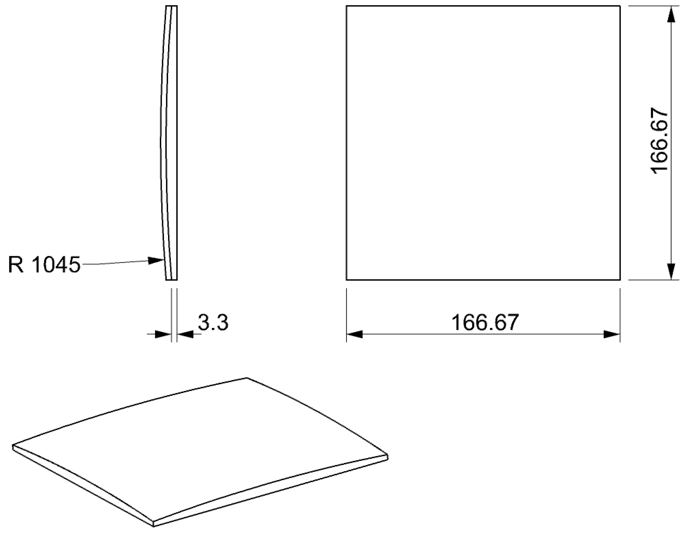
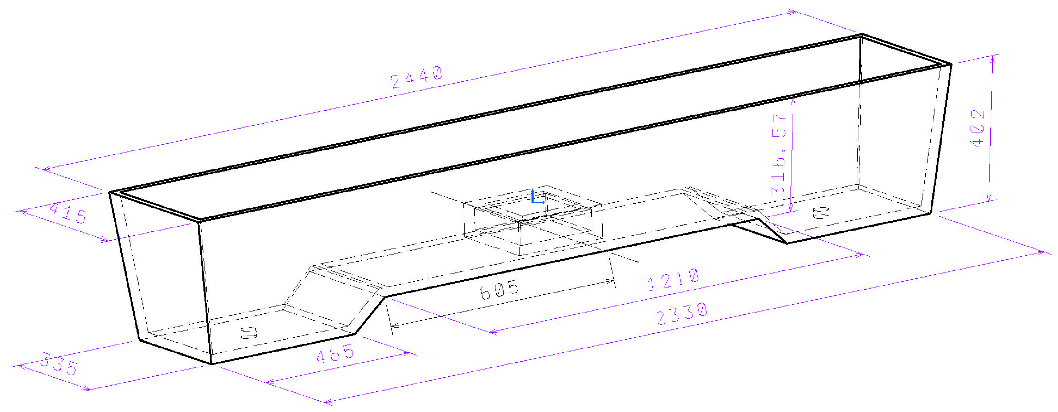
2.1. The “Spheric” Impact Pad

The shape of the spherical impact pad was developed in order to decrease the hydrodynamic drag force of the impinging stream of molten steel. Dimensional analysis of the drag force F provides the dependence.
  F = 1 2 C · ρ · S · v  
where: C—coefficient of drag, ρ —specific mass of fluid, S—size of the reference area (planform area of the pad), and v—references the velocity of impinging stream.
The coefficient C expresses the influence of the shape of the pad on the drag force. The coefficient C is a dimensionless parameter that can be assumed constant for small changes in velocity. The experimental values of the coefficient of drag of objects in a free stream are 1.17 for the square flat plate and 0.40 for the convex hemisphere [10]. The proposed spherical pad has a square planform and the upper surface shape of a large-radius hemisphere.
The shape of the spherical impact pad should, in comparison with the standard impact pad, cause less erosion of the pad surface. Smaller deflection of the stream should reduce the creation of large intensive vortices at the surface of the fluid level. Short-path flow should be suppressed by more intensive mixing at the core of the fluid volume.
Physical modelling is done in a scaled-down model of the tundish at the scale 1:3, made of transparent plastic (PMMA), with water as the fluid medium. The description of the physical model and the experimental method is given in [7,11].
The dimensions of the impact plate were calculated with respect to the scale of the tundish at the ratio 1:3, with the height of the impact plate (Figure 1) set at 9.96 mm due to its position on the bottom of the real tundish (Figure 2). The flow of steel in the tundish equipped with the “Spheric” impact pad is optimized not only for the residence time but also for the nature of the flow, so that this flow promotes the removal of inclusions into the slag and the best conditions for the slag-metal phase interface. This method of modifying the flow is given in [12,13].

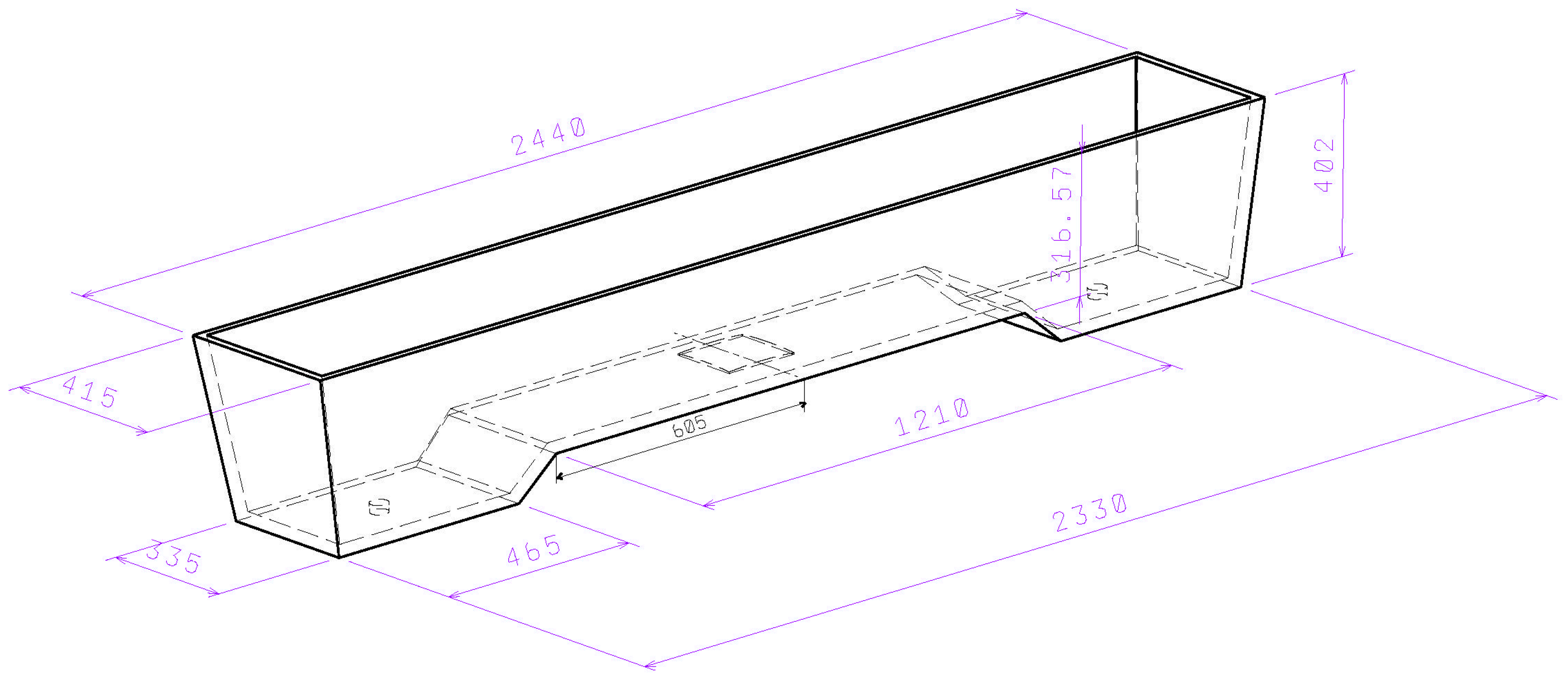
2.2. The Standard Impact Pad

The dimensions and position of the standard impact pad in the tundish are shown in Figure 3.
The measurements were performed in steady-state conditions, so the steel level in the tundish was constant and the amount of steel flowing into the tundish was equal to the amount of steel flowing out from the tundish into the molds.
The C-curve method was used to define the characteristics of the steel flow in the tundish under constant (steady) casting conditions [14,15,16]. Upon reaching the desired level in the mold and stabilizing the casting flow rate, a measured amount of aqueous KCl solution was injected into the ladle shroud. In the ladle shroud and in the submerged entry nozzles, conductivity probes were mounted to measure the change in conductivity of the water due to the added salt, thus obtaining the C-curve [17]. From this curve, we could determine the minimum residence time τmin, which is the minimum time that the impulse of the tracer injected into the ladle shroud (τ0 = 0 s) appears on the probe located in the submerged entry nozzle. Minimum residence time has a significant effect on the duration of flow of inclusions from the steel into the slag [18]. The maximum residence time τmax is the time between t0 and the time of maximum measured concentration of the tracer in the output of the tundish. The maximum residence time refers to the time taken to reach the maximum concentration of the trace element at the output of the tundish [19,20].
Measurements were performed for the tested configurations at flows corresponding to casting speeds of 0.8 m·min−1, 1.2 m·min−1, and 1.6 m·min−1 on a real continuous-casting machine. The length of the ladle shroud on the model corresponded to a real length of 1700 mm. In both configurations the same ladle shroud was used. The distance of the nose of the ladle shroud from the tundish bottom was 203 mm. Thus, when using the standard impact pad it was 183 mm and 194 mm when the spherical impact pad was used.
Each configuration was simulated three times for more accurate statistical evaluation and comparison of the results, and these measurements were then used in each configuration for calculating the mean values reported in the results and graphs. More detailed specifications of each simulated configuration and specific results are presented below.

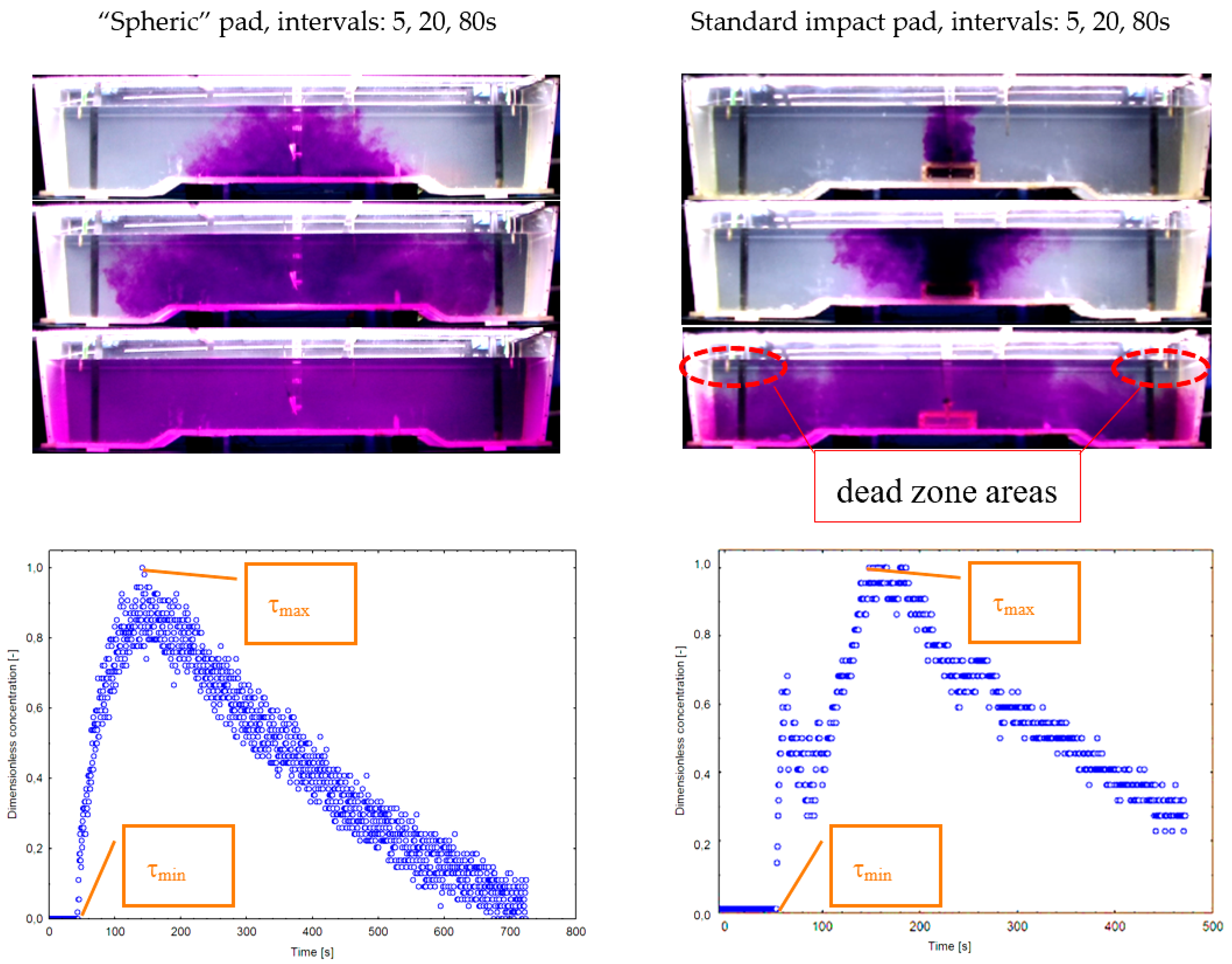
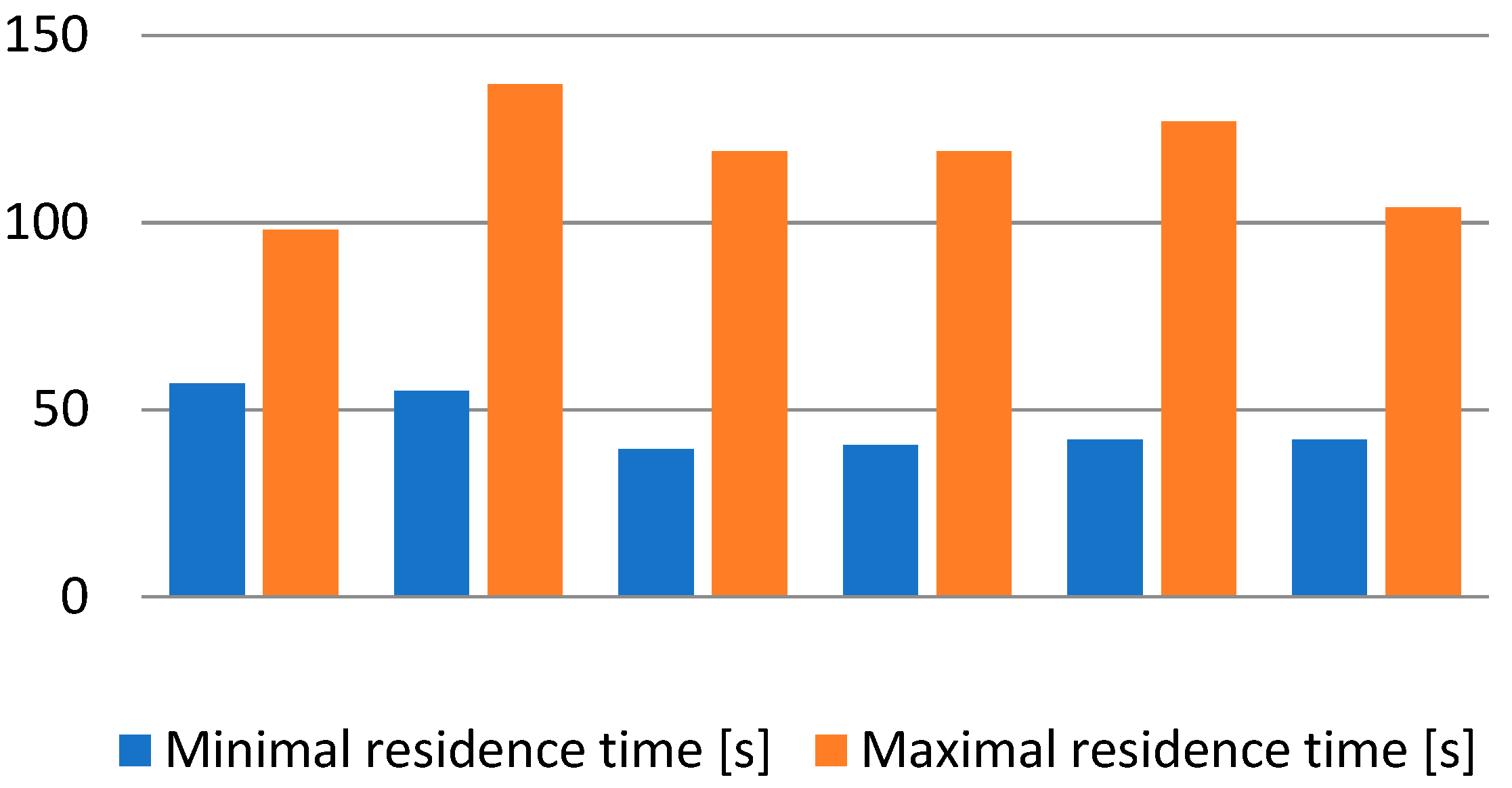
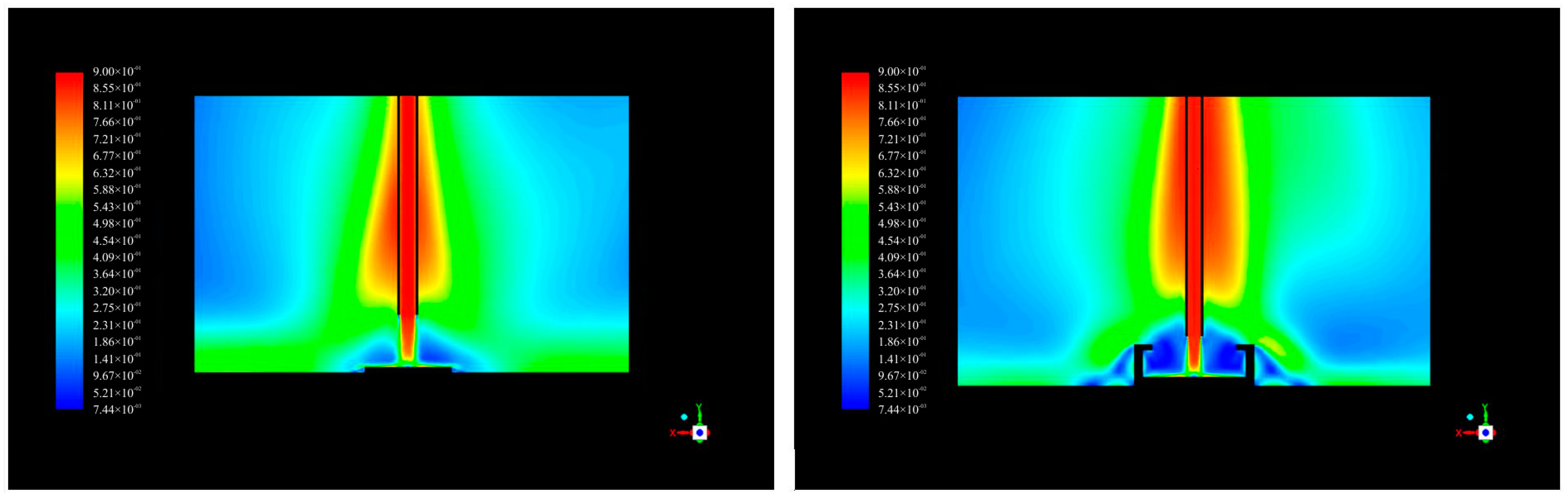
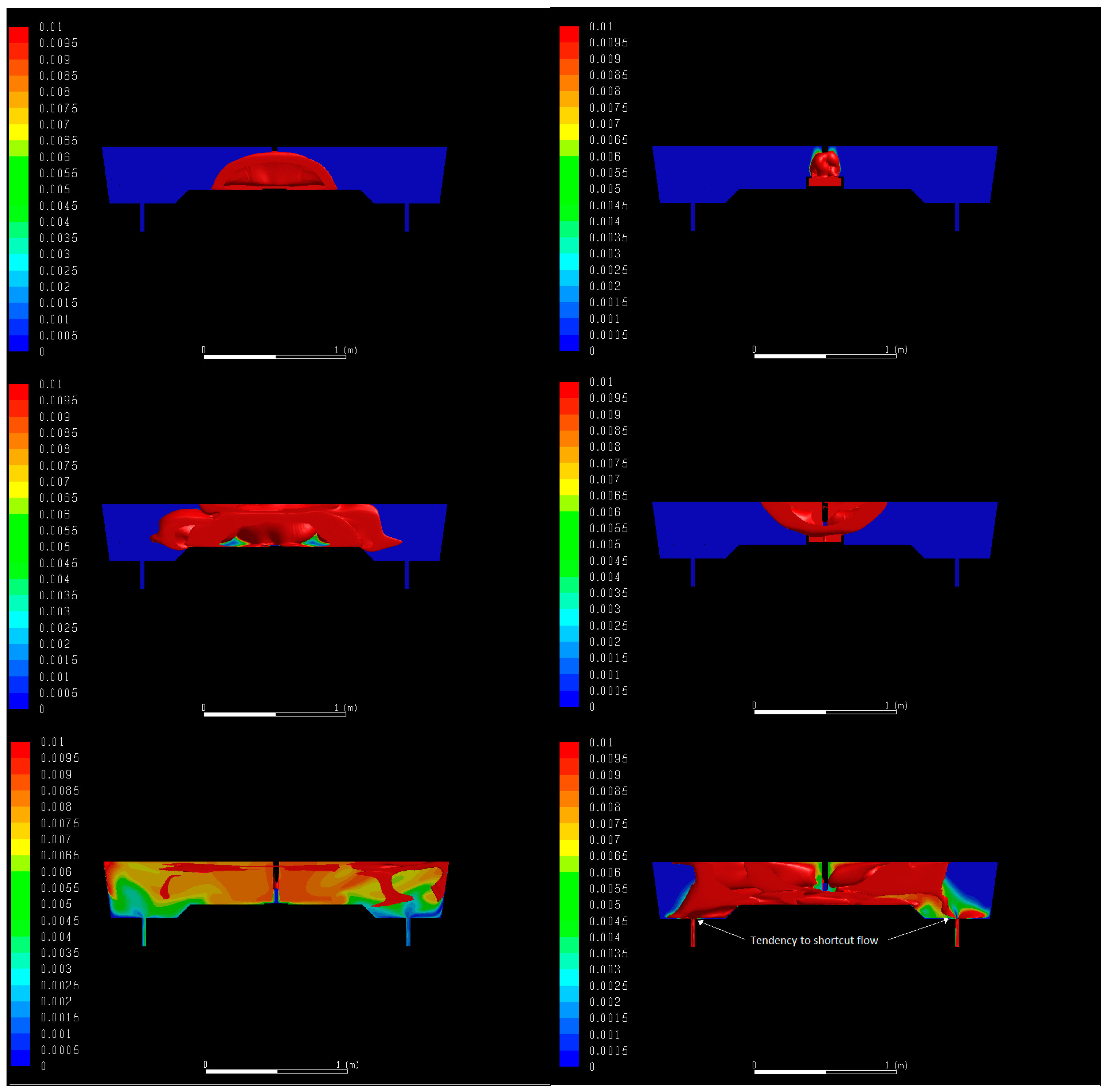
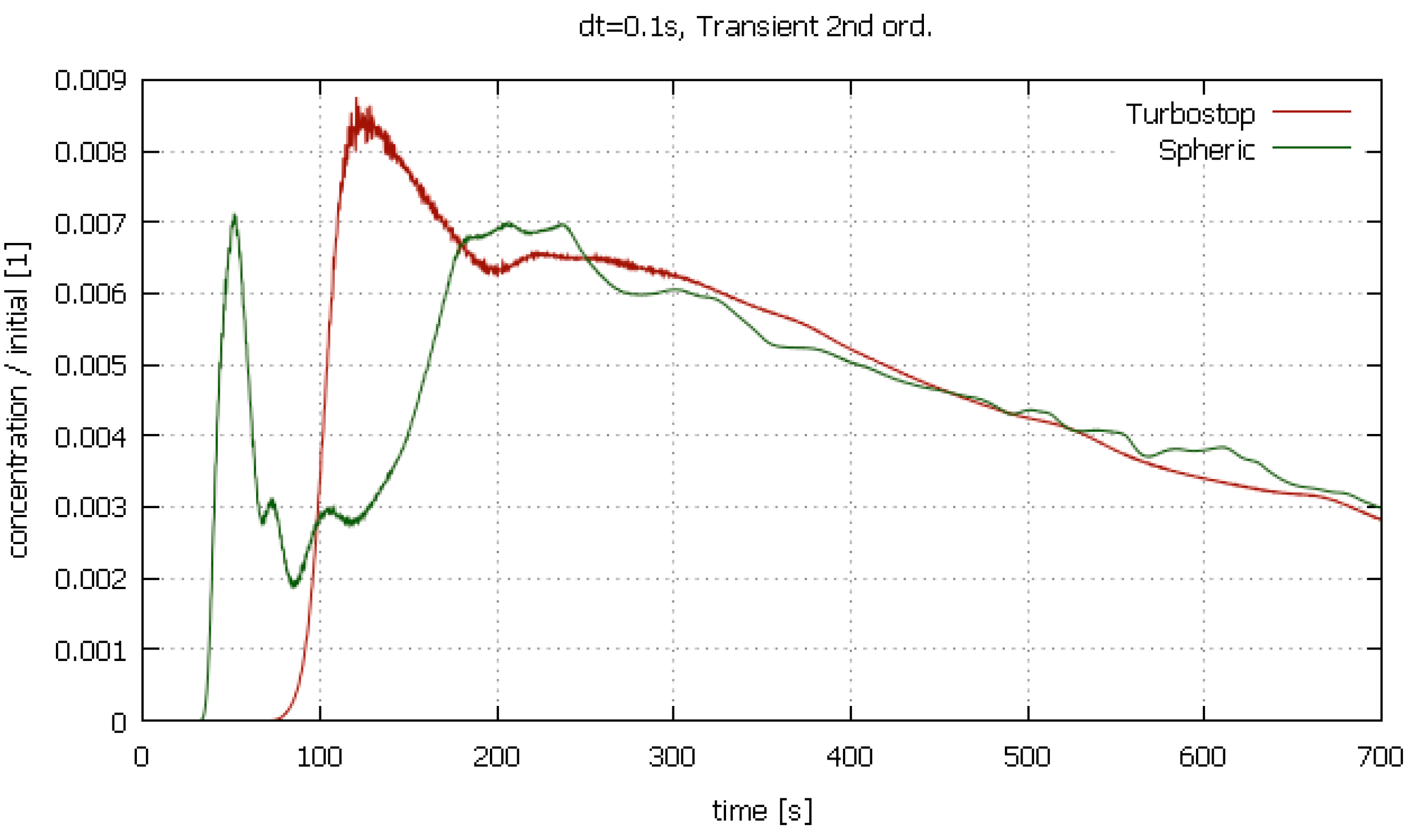
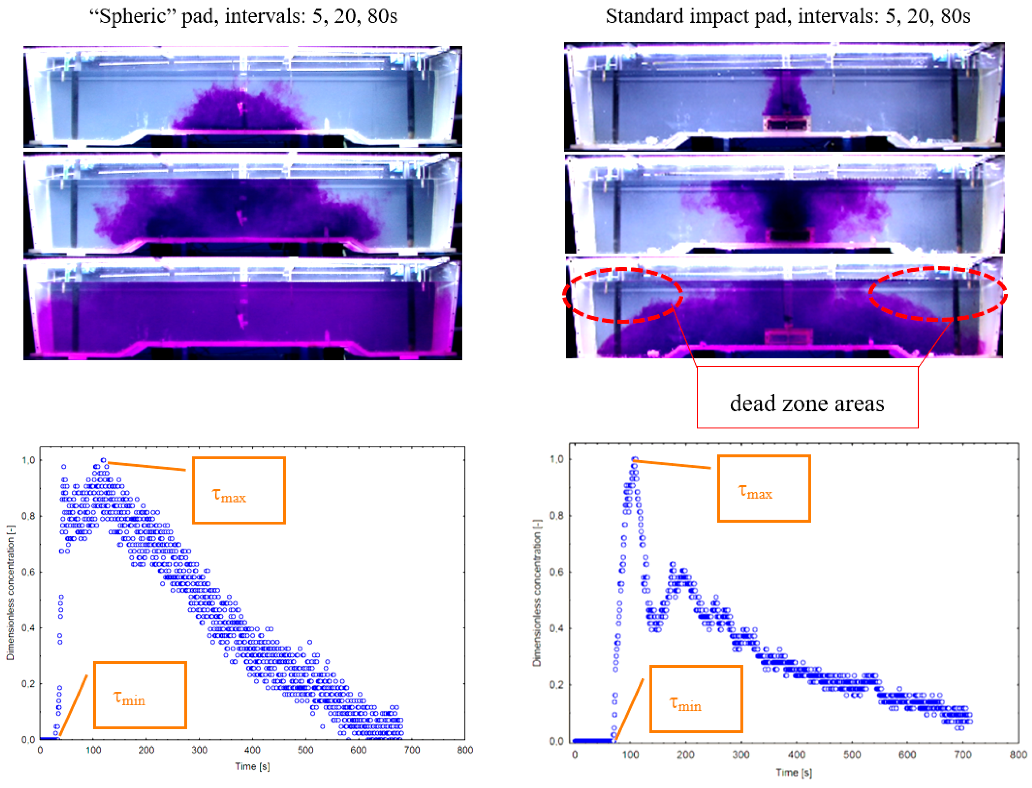
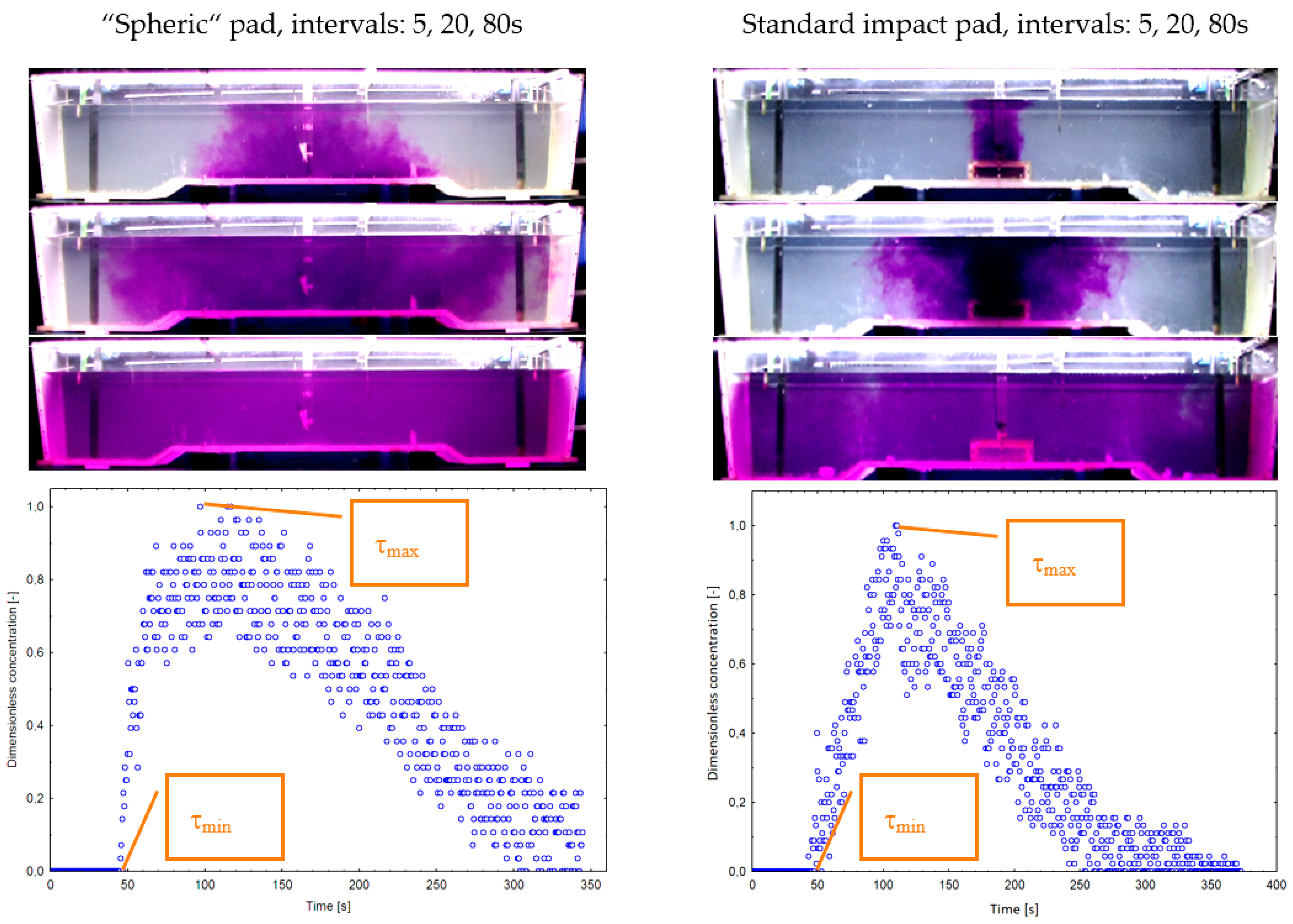
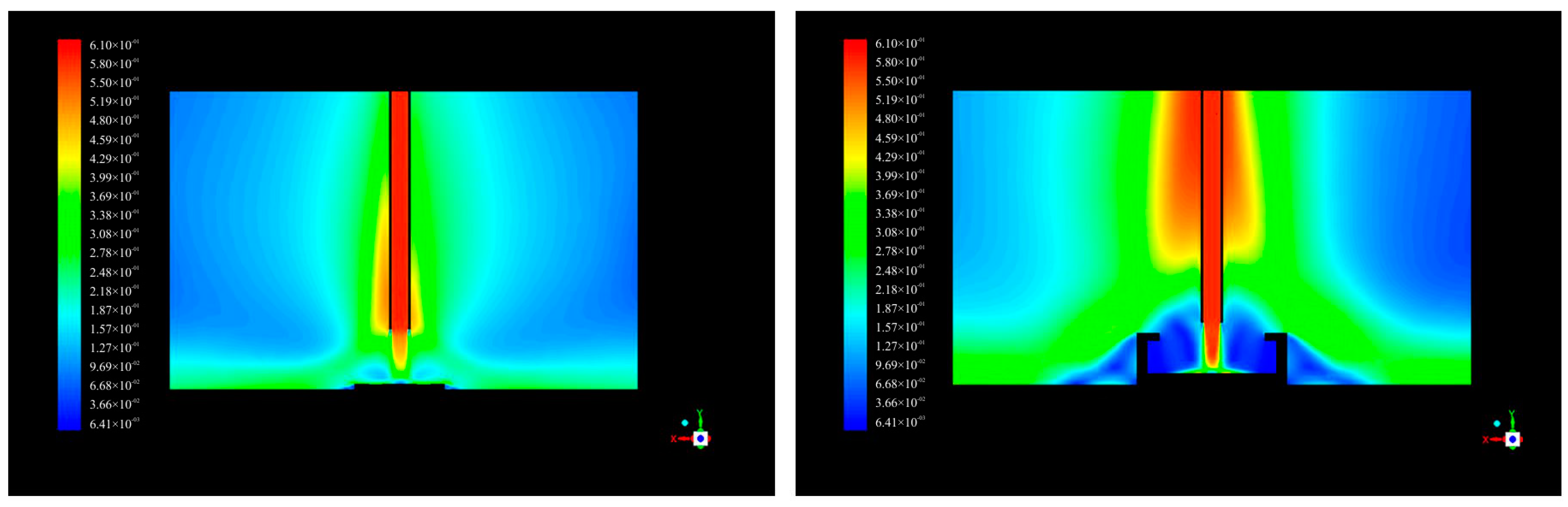
3. Results and Discussion

The initial idea of the “Spheric” impact pad was verified using CFD simulation tools [21,22], (Figure 4 and Figure 5).
Numerical simulation of the flow was computed in the ANSYS Fluent v19.2, the software produced by ANSYS, Canonsburg, PA, USA. ANSYS Fluent computes discrete values of time-dependent Navier–Stokes equations, that is conservation equations of momentum in x-, y-, and z-directions, and the conservation equation of mass. Time-dependent details of turbulent eddies are removed from the Navier–Stokes equations with Reynolds averaging, and the effect of turbulent motion on transport of momentum in the averaged flow is assumed by means of the Boussinesq hypothesis which defines turbulent viscosity. Turbulent viscosity increases the basic, molecular viscosity of the fluid. Computation of turbulent viscosity requires additional equations which are based on the k-omega SST model (Shear Stress Transport, the Menter’s variant of the k-omega model). Change in concentration of the solution in the water is modelled using species transport equations. The solver of the Ansys Fluent is pressure based, so the velocity is obtained from the momentum equation and the pressure is obtained from the pressure equation, which is derived from the continuity equation and the momentum equation. The equations are discretised using the control volume method (CVM). The volume of the domain is divided into discrete control volumes using a computational grid, and the equations are integrated on these volumes and linearized to create algebraic equations for unknown values of velocity, pressure and species fraction. The resulting system of equations has a sparse matrix of coefficients and is solved iteratively using the Gauss–Seidel method. Updating of unknown values is done with the coupled algorithm in the case of the velocity and pressure and sequentially in the case of the species fraction. The values are stored in cell centers. Values at cell faces, needed in convective terms of the equations, are interpolated from the cell-center values by means of upwind discretization schemes. Spatial discretization of the gradient is achieved using the least-square cell-based method. The pressure, momentum, turbulent kinetic energy and specific dissipation use second-order discretization. The species fraction also uses second-order discretization, as does the temporal discretization. The water is modelled as an incompressible fluid with constant density of 998.2 kg m−3 and constant viscosity of 1.002 × 10⁻³ Pa s. The boundary condition at the inlet is uniform velocity of 0.623 m s−1. Both outlets have a predefined velocity of flow equal to half the value of the inlet velocity. The intensity of turbulence at the inlet is 0.1%. The walls are defined with zero slip condition, that is the velocity of the fluid immediately attaching to the wall is equal to zero. The time step is 0.1 s, and the flow is initialized by the flow field developing naturally after 200 s from the steady-state solution. Each time step was computed in 10 iterations. The mesh was created in the ICEM CFD software. The mesh is structured so that is it is composed of only hexahedron discrete volumes arranged in blocks with regular orthogonal structure. The orthogonal geometry of the blocks is projected onto the surface of the walls and the inner geometry of the blocks’ volumes is interpolated from the boundaries. The mesh adjacent to the walls in the region of the boundary layer has perpendicular geometric spacing with the multiple of 1.15 between the heights of consecutive layers of volumes, and the first layer of volume has the height of 0.035 mm in the region of impact flow, and the height of 0.45 mm elsewhere. The worst value of y+ is 1.6 in the region of impact flow, and 0.02–1.0 elsewhere. The mesh contained 2.5 million cells and 2.5 million nodes. The computation ran in the High Performance Computing Centre at the Technical University of Kosice [23,24,25].
Based on the results of CFD simulations, using the “Spheric” impact pad is expected to shorten the residence time compared to the standard impact pad, but on the other hand it is also expected to reduce the swirl of steel around the ladle shroud and reduce the so-called slag “eye” phenomenon. It is assumed that when using a “Spheric” impact pad the mixing area will predominate and the area of dead zones will be intensively reduced. It has also been found that the standard impact pad has a tendency to create a shortcut flow at lower casting speeds.
The proposed impact pad was tested using a model of the real symmetrical, two-strand boat-type tundish at scale 1:3 for the three default casting speeds. The C-curve, residence time, and visual evaluation of the flow in the tundish were selected as comparison criteria. The tracer is an aqueous salt solution of KCl, the concentration of which is monitored by means of the conductivity measurement system, while the flow is evaluated visually using KMnO4 as tracer. Figure 6, Figure 7 and Figure 8 show the results of the simulations comparing the standard and Spheric impact pads. For visual flow comparison, Figure 6, Figure 7 and Figure 8 show the flow of tracer at time intervals of 5, 20 and 80 s after tracer injection. Below these pictures are the corresponding C-curves with highlighted minimum and maximum residence times for each configuration and casting speed.
Table 1 gives a comparison of minimum and maximum residence times for each configuration. The numbers in brackets indicate the percentage difference related to the minimum residence time of the alternative with standard impact pad under similar conditions. Graphical comparison of residence times of all tested configurations is presented in Figure 9.
The difference in flow dynamics in the impact area is shown in Figure 10 and Figure 11, where the standard and “Spheric” impact pads are compared.
The faster vertical circulation of steel up to the slag layer may cause the slag “eye” phenomenon, i.e., slag-free areas of steel surface open to air reoxidation and higher heat losses [26,27].
When using a “Spheric” impact pad, the vertical velocity of the flow around the ladle shroud is significantly lower than when using a standard impact pad. Using the “Spheric” impact pad can eliminate the so-called slag “eye” around the ladle shroud in the slag layer due to the lower vertical velocity of steel flow in this area, in contrast to the standard impact pad.
Another very important function of impact pads is to prevent splashing of molten steel while filling the empty tundish, mainly for safety reasons. A demonstration of the first seconds of filling the empty tundish is shown in Figure 12, and it is clear that the spherical impact pad safely prevents steel splashing.

4. Conclusions

The design of the spherical impact pad with a convex surface was inspired by the differences between the flow past a flat plate and the flow past a sphere. CFD simulations were utilized for the initial testing and approval of this shape of impact pad. Compared to the standard impact pad at a corresponding casting speed of 0.8 m·min−1, the spherical pad was found to shorten the residence time, but on the other hand the flow pattern created by this impact pad could have the benefit of reducing dead zone areas and eliminating any slag “eye” in the slag layer around the ladle shroud. The proposed impact pad has no tendency to short-circuit the flow. The “Spheric” impact pad was therefore subjected to further, more extensive testing using a 1:3 scale physical model of a tundish at flow rates simulating different casting speeds.
Compared to the standard impact pad, based on our measurements of residence time distribution (RTD) curves using the water model, the “Spheric” impact pad shortened the minimum residence times at casting speeds of 0.8 and 1.2 m·min−1, which is on the level of 71% and 76% of the standard impact pad times under identical conditions. On the other hand, the “Spheric” impact pad produced a 6% longer residence time than the standard impact at casting speed 1.6 m·min−1. It should be taken into account that this is only a comparison of impact pads. In both cases, it is possible to fit the tundish with flow modifiers such as dams, weirs and baffles to prolong the residence time of steel in the tundish.
From a visual comparison of flow in the tundish, we can observe that the “Spheric” impact pad produces a better flow pattern than the standard impact pad. It has no tendency to shortcut the flow at lower casting speeds. Moreover, dead zone areas are eliminated using the “Spheric” impact pad. We can predict that using this impact pad in practice will have a positive influence on steel cleanliness due to more dynamic steel flow at the steel-slag interface. Furthermore, the slag “eye” phenomenon can be reduced when the “Spheric” impact pad is used, compared to impact pads with a significant piston flow pattern.
Based on the performed measurements, it can be concluded that the “Spheric” impact pad has great potential to optimize the flow of steel in the tundish, and that in combination with the appropriate “tundish furniture” it can become a new part of modern tundish metallurgy with significant influence on the final quality and cleanliness of conticast steel.

Author Contributions

B.B. performed the physical simulations, wrote the manuscript, and arranged the funding; I.P. found and proposed the “Spheric” impact pad; P.D. evaluated the results of the physical simulations; P.G. performed the CFD simulations; D.B. designed the experiments performed on the CCM water model; M.H. revised the original manuscript.

Funding

This research was funded by [VEGA MŠ SR a SAV] grant number [1/0868/17].

Conflicts of Interest

The authors declare no conflicts of interest.

References

  1. Worldsteel Association. Steel Statistical Yearbook 2016. Available online: https://www.worldsteel.org/publications/bookshop/product-details.~Steel-Statistical-Yearbook-2016~PRODUCT~SSY2016~.html (accessed on 9 November 2018).
  2. Michalek, K.; Gryc, K.; Socha, L.; Tkadlečková, M.; Saternus, M.; Pieprzyca, J.; Merder, T.; Pindor, L. Physical modelling of tundish slag entrainment under various technological conditions. Arch. Metall. Mater. 2017, 62, 1467–1471. [Google Scholar] [CrossRef]
  3. Warzecha, M. Numerical Modelling of Non-Metallic Inclusion Separation in a Continuous Casting Tundish. Available online: https://www.researchgate.net/publication/221913237 (accessed on 9 November 2018).
  4. Braun, A.; Warzecha, M.; Pfeifer, H. Numerical and physical modeling of steel flow in a two-strand tundish for different casting conditions. Metall. Mater. Trans. B 2010, 41, 549–559. [Google Scholar] [CrossRef]
  5. Chattopadhyay, K.; Isac, M.; Guthrie, R.I.L. Physical and mathematical modelling of steelmaking tundish operations: A review of the last decade (1999–2009). ISIJ Int. 2010, 50, 331–348. [Google Scholar] [CrossRef]
  6. Kowitwarangkul, P.; Harnsihacacha, A. Tracer injection simulations and RTD analysis for the flow in a 3-strand steelmaking tundish. Key Eng. Mater. 2016, 728, 72–77. [Google Scholar] [CrossRef]
  7. Buľko, B.; Kijac, J. Optimization of tundish equipment. Acta Metall. Slovaca 2010, 16, 76–83. [Google Scholar]
  8. Buľko, B.; Molnár, M.; Demeter, P. Physical modeling of different configurations of a tundish for casting grades of steel that must satisfy stringent requirements on quality. Metallurgist 2014, 57, 976–980. [Google Scholar] [CrossRef]
  9. Chatterjee, D. Designing of a novel shroud for improving the quality of steel in tundish. Adv. Mater. Res. 2012, 585, 359–363. [Google Scholar] [CrossRef]
  10. Hoerner, S.F. Fluid Dynamic Drag: Practical Information on Aerodynamic Drag and Hydrodynamic Resistance; Hoerner Fluid Dynamics: Bakersfield, CA, USA, 1965. [Google Scholar]
  11. Laboratory of Simulation of Flow Processes. Available online: https://ohaz.umet.fmmr.tuke.sk/lspp/index_en.html (accessed on 17 September 2018).
  12. Priesol, I. A Method of Molten Metal Casting Utilizing an Impact Pad in the Tundish. International Patent Application No. PCT/IB2016/056207, 10 October 2016. [Google Scholar]
  13. Priesol, I. Spôsob Liatia Roztaveného Kovu s Využitím Dopadovej Dosky v Medzipanve. International Patent Classification: B22D 11/10 B22D 41/00, Application No. 109-2016, 11 October 2016; B22D 11/00 B22D 41/00, Application No. 89-2016, 10 October 2016. [Google Scholar]
  14. Michalek, K.; Gryc, K.; Socha, L.; Tkadlečková, M.; Saternus, M.; Pieprzyca, J.; Merder, T.; Pindor, L. Study of tundish slag entrainment using physical modeling. Arch. Metall. Mater. 2016, 61, 257–260. [Google Scholar] [CrossRef]
  15. Acta Metallurgica Slovaca. Available online: http://www.ams.tuke.sk/data/ams_online/2010/number2/mag01/mag01.pdf (accessed on 17 September 2018).
  16. Gryc, K.; Michalek, K.; Hudzieczek, Z.; Tkadlečková, M. Physical modelling of flow patterns in a 5-strand asymmetrical tundish with baffles. In Proceedings of the Metal 2010—19th International Conference on Metallurgy and Materials, Poruba, Czech Republic, 18–20 May 2010. [Google Scholar]
  17. Sahai, Y.; Emi, T. Melt flow characterization in continuous casting tundishes. ISIJ Int. 1996, 36, 667–672. [Google Scholar] [CrossRef]
  18. Väyrynen, P.; Wang, S.; Louhenkilpi, S.; Holappa, L. Modeling and removal of inclusions in continuous casting. In Proceedings of the Materials Science and Technology 2009—International Symposium on Inclusions and Clean Steel 2009, Pittsburgh, PA, USA, 25–29 October 2009. [Google Scholar]
  19. Michalek, K. Využití Fyzikálního a Numerického Modelování pro Optimalizaci Metalurgických Procesů; Vysoká škola Báňská—Technická Univerzita: Ostrava, Czech Republic, 2001; ISBN 80-7078-861-5. [Google Scholar]
  20. Falkus, J.; Lamut, J. Model testing of the bath flow through the Tundish of the continuous casting machine. Arch. Metall. Mater. 2005, 50, 709–718. [Google Scholar]
  21. Ansys Fluent 12.0 User’s Guide. 2009. Available online: http://users.ugent.be/~mvbelleg/flug-12-0.pdf (accessed on 22 August 2018).
  22. Nastac, L.; Zhang, L.; Thomas, B.G.; Zhu, M.; Ludwig, A.; Sabau, A.S.; Pericleous, K.; Combeau, H. CFD Modeling and Simulation in Materials Processing 2016; Springer International Publishing: New York, NY, USA, 2016. [Google Scholar]
  23. Gardin, P.; Brunet, M.; Domgin, J.F.; Pericleous, K. An experimental and numerical CFD study of turbulence in a tundish container. Appl. Math. Model. 2002, 26, 323–336. [Google Scholar] [CrossRef]
  24. Mazumdar, D.; Guthrie, R.I.L. The physical and mathematical modelling of continuous casting Tundish systems. ISIJ Int. 1999, 39, 524–547. [Google Scholar] [CrossRef]
  25. Liu, S.; Yang, X.; Du, L.; Li, L.; Liu, C. Hydrodynamic and mathematical simulations of flow field and temperature profile in an asymmetrical t-type single-strand continuous casting Tundish. ISIJ Int. 2008, 48, 1712–1721. [Google Scholar] [CrossRef]
  26. Chatterjee, S.; Chattopadhyay, K. Formation of slag ‘eye’ in an inert gas shrouded Tundish. ISIJ Int. 2015, 55, 1416–1424. [Google Scholar] [CrossRef]
  27. Zhang, L.; Thomas, B.G. State of the art in evaluation and control of steel cleanliness. ISIJ Int. 2003, 43, 271–291. [Google Scholar] [CrossRef]
Figure 1. The “Spheric” impact pad.
Metals 08 00944 g001
Figure 2. Position of the “Spheric“ impact pad in the tundish.
Metals 08 00944 g002
Figure 3. Position of the standard impact pad.
Metals 08 00944 g003
Figure 4. Comparison of fluid flow for “Spheric” impact pad and for standard impact pad at simulated casting speed 0.8 m·min−1—CFD simulation.
Metals 08 00944 g004
Figure 5. Comparison of C-curves for the “Spheric” impact pad and for standard impact pad @ 0.8 m·min−1—CFD simulation.
Metals 08 00944 g005
Figure 6. Visual and graphical comparison of flow for “Spheric” impact pad and for standard impact pad at simulated casting speed 0.8 m·min−1—physical simulation.
Metals 08 00944 g006
Figure 7. Visual and graphical comparison of flow for “Spheric” impact pad and for standard impact pad at simulated casting speed 1.2 m·min−1—physical simulation.
Metals 08 00944 g007
Figure 8. Visual and graphical comparison of flow for “Spheric” impact pad and for standard impact pad at simulated casting speed 1.6 m·min−1—physical simulation.
Metals 08 00944 g008
Figure 9. Graphical comparison of residence times of all tested configurations.
Metals 08 00944 g009
Figure 10. Comparison of velocity areas for “Spheric” and standard impact pads @ 0.8 m·min−1.
Metals 08 00944 g010
Figure 11. Comparison of velocity areas for “Spheric” and standard impact pads @ 1.2 m·min−1.
Metals 08 00944 g011
Figure 12. First seconds of filling an empty tundish, using the “Spheric” impact pad.
Metals 08 00944 g012
Table 1. Comparison of residence times for all tested configurations.
ConfigurationCasting SpeedMinimal Residence Time (s)Maximal Residence Time (s)
Standard Impact Pad0.8 m·min−15798
1.2 m·min−155137
1.6 m·min−139.5119
Spheric Impact Pad0.8 m·min−140.5 (71%)119
1.2 m·min−142 (76%)127
1.6 m·min−142 (106%)104

