Damage Mechanism of Copper Staves in a 3200 m3 Blast Furnace


Abstract
:1. Introduction
2. Materials and Methods
3. Results
3.1. Chemical Composition
3.2. Thermal Conductivity
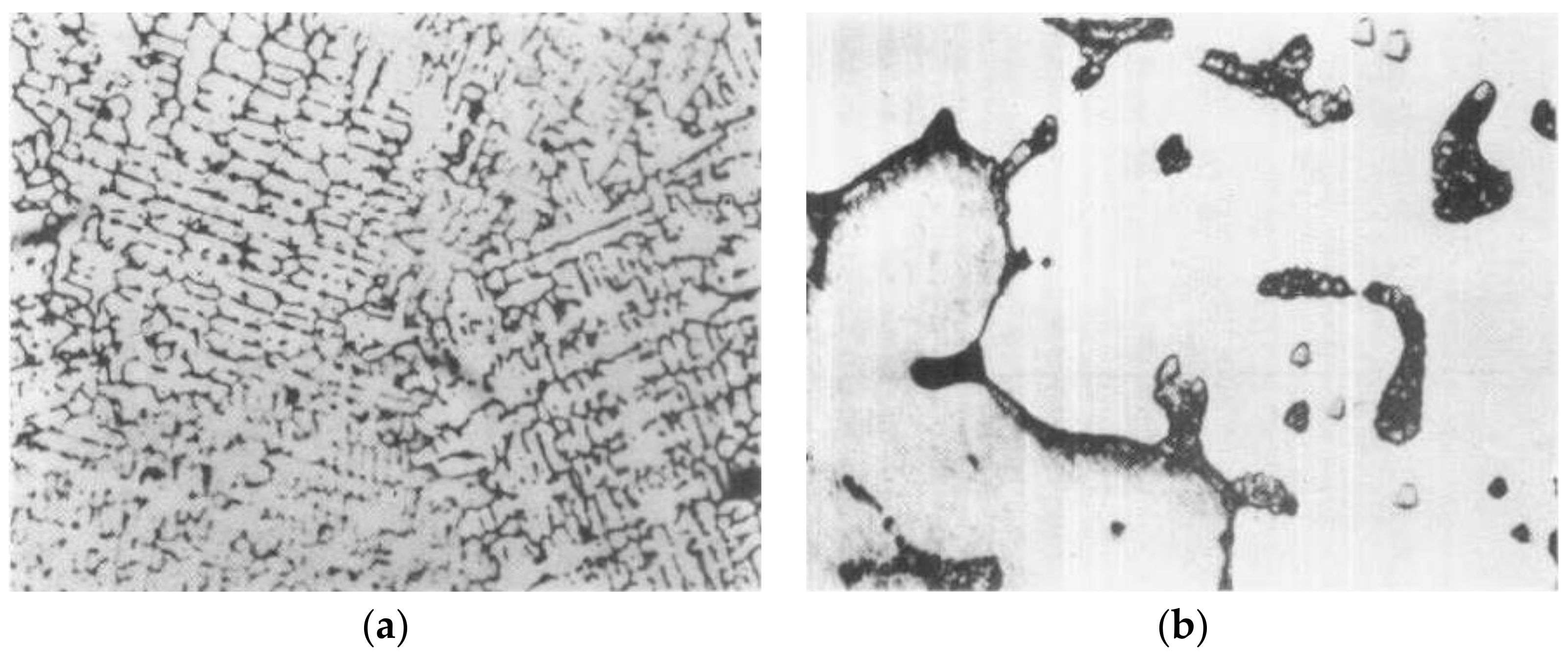
3.3. Metallographic Aspects
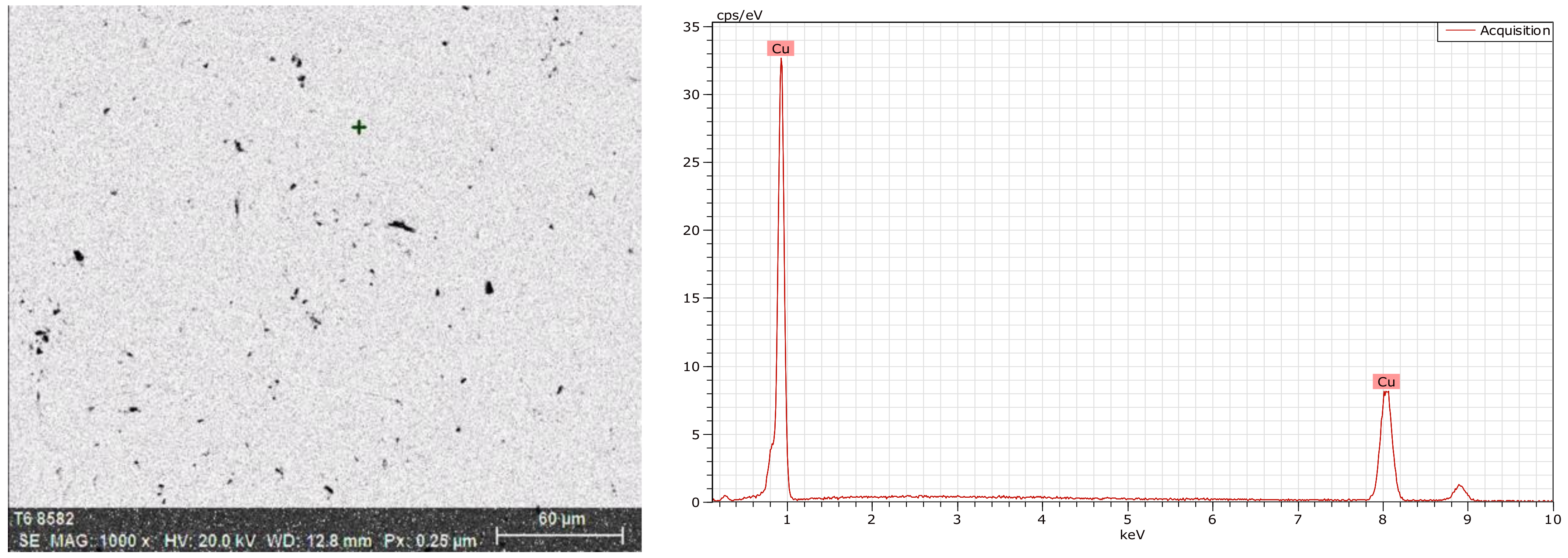
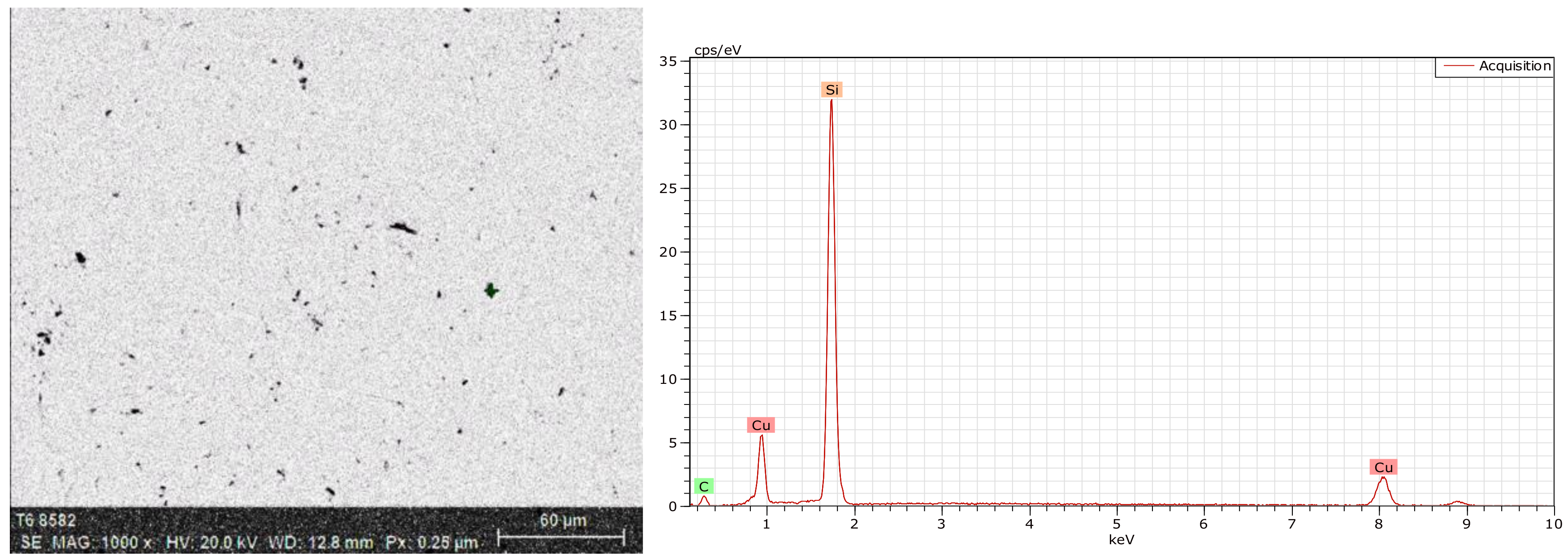
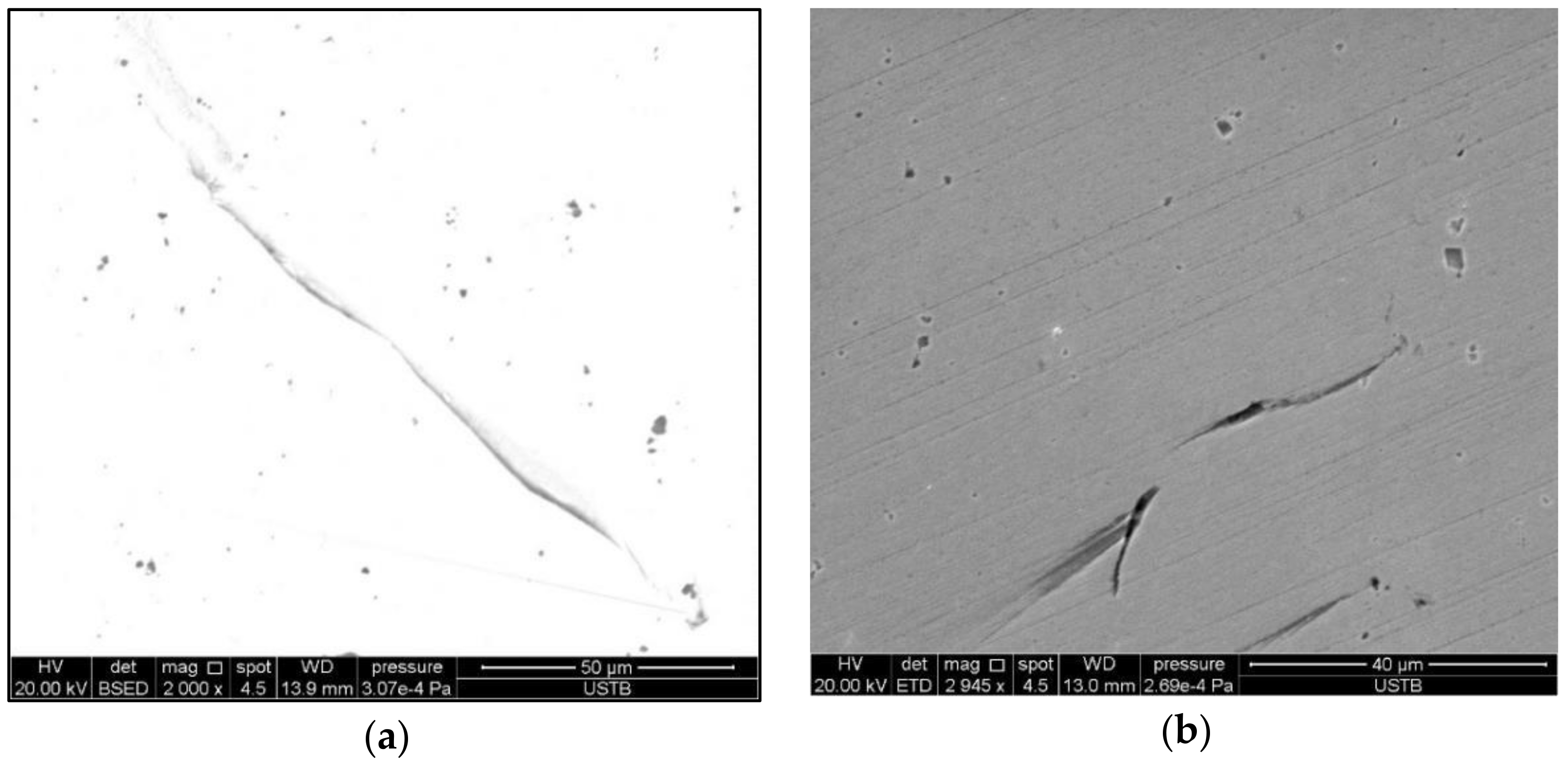
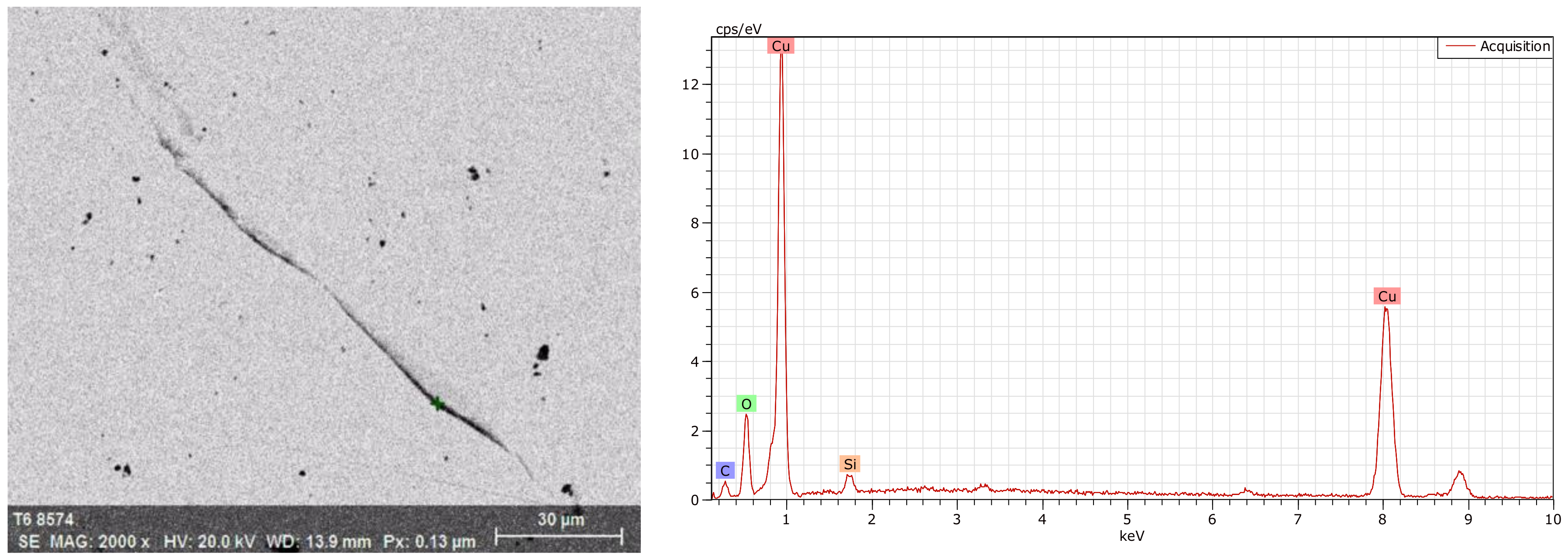
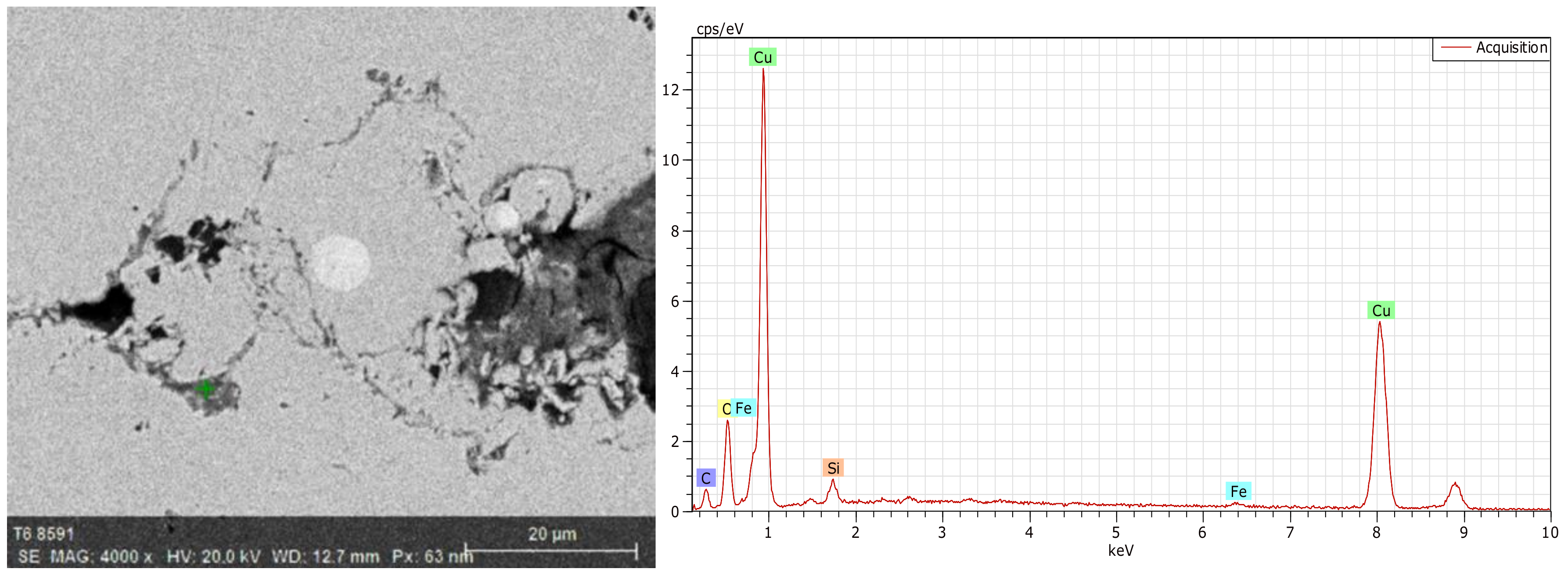
3.4. Microstructure
4. Discussion
4.1. Materials
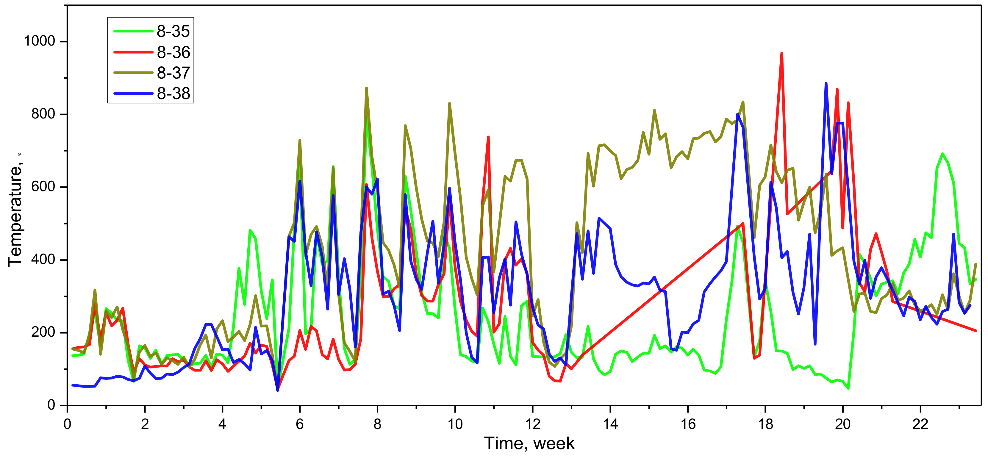
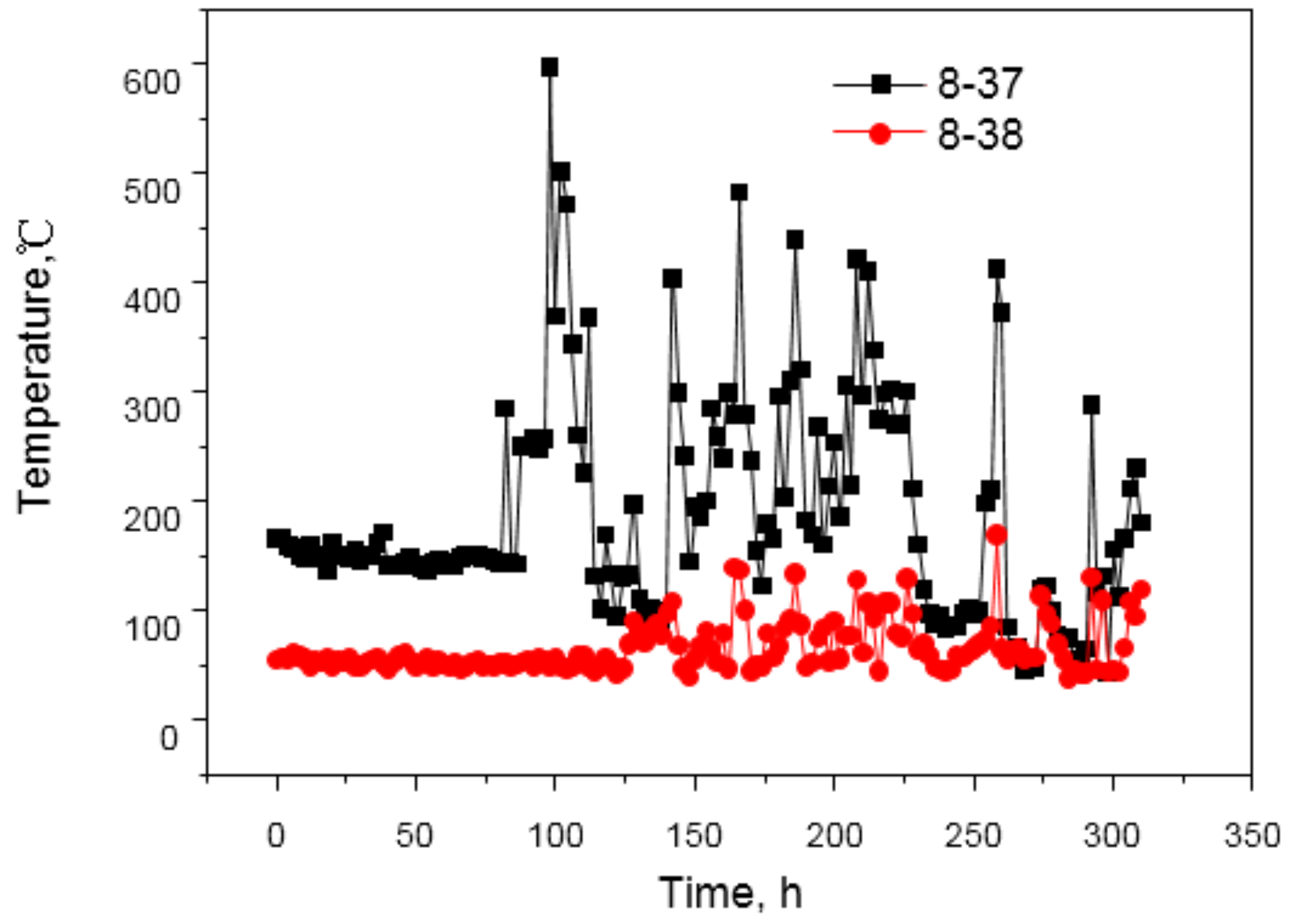
4.2. Working State
4.3. Damage Process
5. Conclusions
- (1)
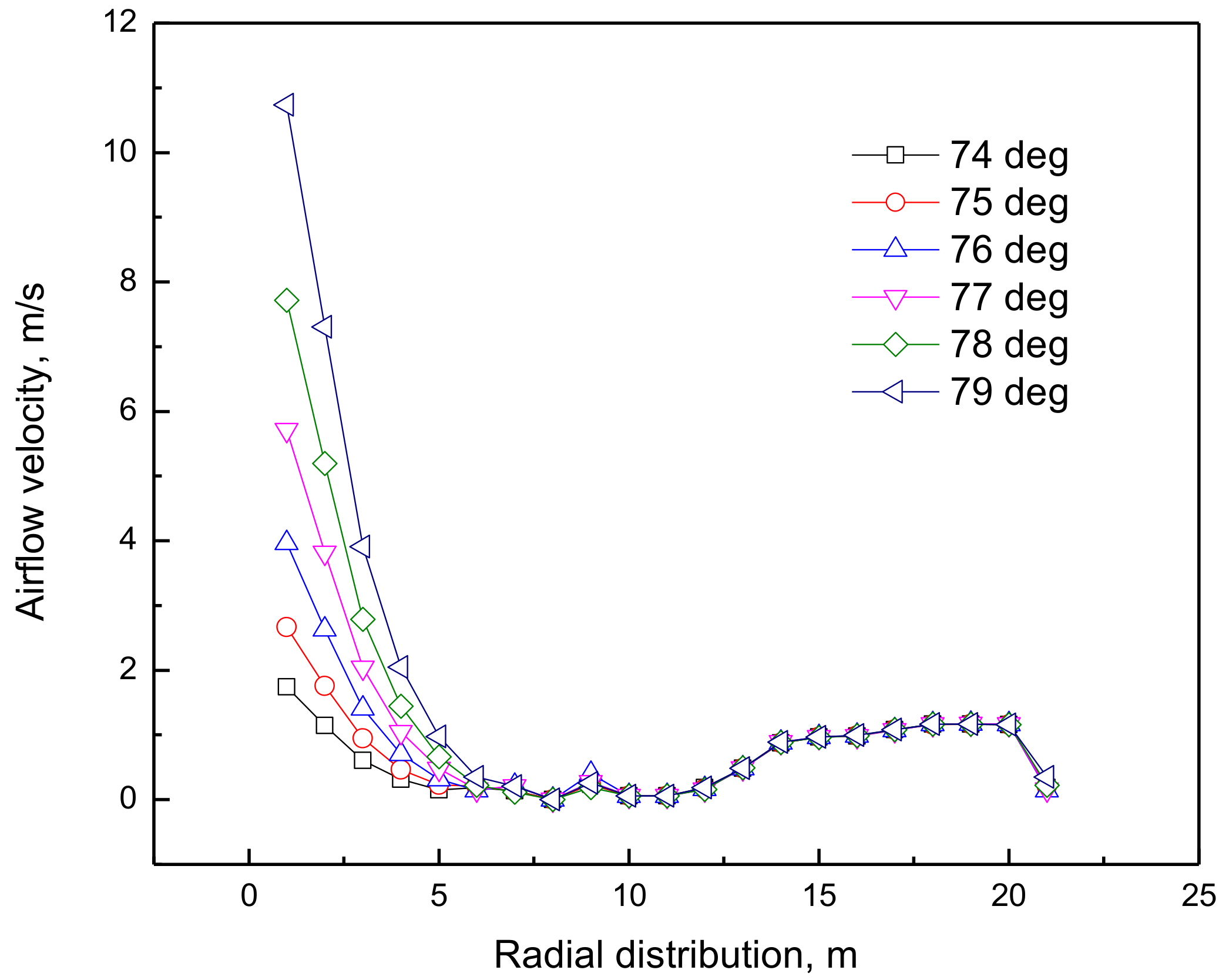
- The poor raw materials, especially poor coke quality, and the large bosh angle caused the development of the edge airflow to maintain the high smelting strength. The high-temperature and high-speed airflow carrying the coke breeze generated by the deterioration had a strong scouring effect on the refractory bricks, which were continuously eroded by the slag, iron, and airflow under thermal stress and high temperature.
- (2)
- Slag crusts were difficult to be stable due to the increase of temperature, causing damage to the water pipes. The cooling strength inevitably declined after remedy, resulting in an increase in the temperature of copper staves and a decrease in the capacity to form slag crusts.
- (3)
- The hydrogen attack happened under the reducing atmosphere when the temperature was greater than 370 °C, leading to the development of cracks at the hot surface. As a result, the performance of copper staves such as the hardness at the high temperature and the wear resistance decreased. Copper staves were quickly worn to form a smooth surface under continuous scouring of the edge airflow, thus, it became more difficult to form slag crusts. Under the hydrogen attack and the scouring of the edge airflow at the high temperature, copper staves finally failed.
Author Contributions
Funding
Conflicts of Interest
References
- Frolova, I.B.; Minkin, V.M.; Frolov, V.A.; Yukhimenko, V.I. The slag crust in high-temperature iron ore smelting. Refract. Ind. Ceram. 1976, 17, 429–432. [Google Scholar] [CrossRef]
- Zamoskovtsev, D.E.; Lednov, A.Y.; Kishchuk, V.D.; Chaplouskii, A.A. Ultrasonic diagnosis in control of the slag crust. Metallurgist 1997, 41, 436. [Google Scholar] [CrossRef]
- An, J.Q.; Zhang, J.L.; Wu, M.; She, J.H.; Terano, T. Soft-sensing method for slag-crust state of blast furnace based on two-dimensional decision fusion. Neurocomputing 2018, 315, 405–411. [Google Scholar] [CrossRef]
- Jiao, K.X.; Zhang, J.L.; Liu, Z.J.; Liu, F.; Liang, L.S. Formation mechanism of the graphite-rich protective layer in blast furnace hearths. Int. J. Miner. Metall. Mater. 2016, 23, 16–24. [Google Scholar] [CrossRef]
- Zhang, H.; Jiao, K.X.; Zhang, J.L.; Chen, Y.B. A new method for evaluating cooling capacity of blast furnace cooling stave. Ironmak. Steelmak. 2018. [CrossRef]
- Mohanty, T.R.; Sahoo, S.K.; Moharana, M.K. Computational modeling of blast furnace save cooler based on steady state heat transfer analysis. Procedia Eng. 2015, 127, 940–946. [Google Scholar] [CrossRef]
- Xu, X.; Wu, L.J.; Lu, Z.A. Performance optimization criterion of blast furnace stave. Int. J. Heat Mass Transf. 2017, 105, 102–108. [Google Scholar] [CrossRef]
- Wu, L.J.; Zhou, W.G.; Su, Y.L.; Li, X.J. Experimental and operational thermal studies on blast furnace cast steel staves. Ironmak. Steelmak. 2008, 35, 179–182. [Google Scholar] [CrossRef]
- Yeh, C.P.; Ho, C.K.; Yang, R.J. Conjugate heat transfer analysis of copper staves and sensor bars in a blast furnace for various refractory lining thickness. Int. Commun. Heat Mass Transf. 2012, 39, 58–65. [Google Scholar] [CrossRef]
- Balamurugan, S.; Shunmugasundaram, R.; Patra, M.; Pani, S.; Dutta, M. Evaluation of copper stave remnant thickness in blast furnace using ultrasonic method. ISIJ Int. 2015, 55, 605–610. [Google Scholar] [CrossRef]
- Liu, Z.J.; Zhang, J.L.; Zuo, H.B.; Yang, T.J. Recent progress on long service life design of Chinese blast furnace hearth. ISIJ Int. 2012, 52, 1713–1723. [Google Scholar] [CrossRef]
- Chen, W.C.; Cheng, W.T. Numerical simulation on forced convective heat transfer of titanium dioxide/water nanofluid in the cooling stave of blast furnace. Int. Commun. Heat Mass Transf. 2016, 71, 208–215. [Google Scholar] [CrossRef]
- Liu, Q.; Cheng, S.S. Heat transfer and thermal deformation analyses of a copper stave used in the belly and lower shaft area of a blast furnace. Inter. J. Therm. Sci. 2016, 100, 202–212. [Google Scholar] [CrossRef]
- Wu, T.; Cheng, S.S. Model of forming-accretion on blast furnace copper stave and industrial application. J. Iron Steel Res. Int. 2012, 19, 1–5. [Google Scholar] [CrossRef]
- Xie, N.Q.; Cheng, S.S. Analysis of effect of gas temperature on cooling stave of blast furnace. J. Iron Steel Res. Int. 2010, 17, 1–6. [Google Scholar] [CrossRef]
- Deng, Y.; Jiao, K.X.; Wu, Q.C.; Zhang, J.L.; Yang, T.J. Damage mechanism of copper stave used in blast furnace. Ironmak. Steelmak. 2017. [CrossRef]
- Wang, X.L. Iron and Steel Metallurgy (Ironmaking), 3rd ed.; Metallurgical Industry Press: Beijing, China, 2013; p. 391. ISBN 978-7-5024-6130-0. [Google Scholar]
- Hua, J.S.; Zhu, J.; Li, X.M.; Ma, Y.P. Principles of Transfer in Metallurgy, 1st ed.; Northwestern Polytechnical University Press: Xi’an, China, 2005; p. 88. ISBN 7-5612-1904-0. [Google Scholar]
- Li, Y.L.; Cheng, S.S. Cooling capacity recovery of copper stave based on heat transfer. J. Iron Steel Res. 2012, 24, 5. [Google Scholar] [CrossRef]
- Zhang, J.L.; Chen, Y.X.; Fan, Z.Y.; Hu, Z.W.; Yang, T.J.; Tatsuro, A. Influence of profile of blast furnace on motion and stress of burden by 3D-DEM. J. Iron Steel Res. Int. 2011, 18, 1–6. [Google Scholar] [CrossRef]
- Li, F.G.; Zhang, J.L. Stress distribution law and adherent dross stability of the copper cooling stave with variable slag coating thickness. Chin. J. Eng. 2017, 39, 389–398. [Google Scholar] [CrossRef]
- Zhong, W.J. Practical Manual for Processing Technology of Copper, 1st ed.; Metallurgical Industry Press: Beijing, China, 2007; p. 78. ISBN 978-7-5024-4100-5. [Google Scholar]


| Si | P | S | Ni | Ag | As | Bi |
|---|---|---|---|---|---|---|
| 0.001 | 0.002 | 0.004 | 0.002 | -- | 0.002 | 0.001 |
| Cu + Ag | O | Sb | Fe | Pb | Sn | Zn |
| 99.95 | 0.003 | 0.002 | 0.004 | 0.004 | 0.002 | 0.003 |
| Sample | Si | P | S | Ni | Ag | As | Bi |
|---|---|---|---|---|---|---|---|
| 1 | <0.0005 | <0.0005 | 0.0013 | <0.0005 | 0.0003 | <0.0005 | <0.00001 |
| 2 | <0.0005 | <0.0005 | 0.0014 | <0.0005 | 0.0005 | <0.0005 | <0.00001 |
| 3 | <0.0005 | <0.0005 | 0.0013 | <0.0005 | 0.0008 | <0.0005 | <0.00001 |
| 4 | <0.0005 | <0.0005 | 0.0014 | <0.0005 | 0.0008 | <0.0005 | <0.00001 |
| 5 | <0.0005 | <0.0005 | 0.0012 | <0.0005 | 0.0008 | <0.0005 | 0.00003 |
| Sample | Cu + Ag | O | Sb | Fe | Pb | Sn | Zn |
| 1 | 99.98 | 0.0005 | <0.0001 | 0.003 | 0.0002 | <0.0001 | <0.0005 |
| 2 | 99.97 | 0.0001 | <0.0001 | 0.003 | 0.0002 | <0.0001 | 0.0015 |
| 3 | 99.96 | 0.0004 | <0.0001 | 0.002 | 0.0002 | <0.0001 | <0.0005 |
| 4 | 99.96 | 0.0003 | <0.0001 | 0.006 | 0.0003 | <0.0001 | 0.0015 |
| 5 | 99.96 | <0.0001 | <0.0001 | 0.002 | 0.0015 | <0.0001 | 0.013 |
| C | Mn | P | S | Ti | As |
|---|---|---|---|---|---|
| 2.54 | 0.21 | 0.12 | 0.43 | 0.18 | <0.005 |
| Ca | K | Na | Pb | SiO2 | Zn |
| 12.80 | 0.54 | 0.24 | 0.0026 | 18.72 | 0.34 |
| Sample | Room Temperature | 100 °C | 200 °C |
|---|---|---|---|
| 1 | 380.83 | 358.08 | 347.97 |
| 2 | 394.22 | 372.46 | 357.48 |
| 3 | 382.02 | 359.06 | 349.26 |
| 4 | 379.84 | 362.41 | 350.60 |
| 5 | 364.82 | 354.23 | 348.46 |
© 2018 by the authors. Licensee MDPI, Basel, Switzerland. This article is an open access article distributed under the terms and conditions of the Creative Commons Attribution (CC BY) license (http://creativecommons.org/licenses/by/4.0/).
Share and Cite
Zuo, H.; Wang, Y.; Wang, X. Damage Mechanism of Copper Staves in a 3200 m3 Blast Furnace. Metals 2018, 8, 943. https://doi.org/10.3390/met8110943
Zuo H, Wang Y, Wang X. Damage Mechanism of Copper Staves in a 3200 m3 Blast Furnace. Metals. 2018; 8(11):943. https://doi.org/10.3390/met8110943
Chicago/Turabian StyleZuo, Haibin, Yajie Wang, and Xuebin Wang. 2018. "Damage Mechanism of Copper Staves in a 3200 m3 Blast Furnace" Metals 8, no. 11: 943. https://doi.org/10.3390/met8110943
APA StyleZuo, H., Wang, Y., & Wang, X. (2018). Damage Mechanism of Copper Staves in a 3200 m3 Blast Furnace. Metals, 8(11), 943. https://doi.org/10.3390/met8110943