Abstract
Results of dynamic tensile testing of three-step low-temperature-transformed nanostructured bainitic steel and quenching and partitioning martensitic steel at different strain rates (0.1–500 s−1) are reported here. The results showed that the high carbon film-like austenite was much more stable than the low carbon blocky austenite during deformation. The nanostructured bainite steel exhibited the more remarkable dynamic tensile properties due to the better transformation-induced plasticity effect and strain rate hardening effect exhibited by stable film-like retained austenite. The big gap in engineering stress and strain curves occurred at a higher strain rate (100–200 s−1) for the nanostructured bainite steel because of the better stability of film-like austenite. Therefore, the present study is able to assist in explaining the effect of carbon content in retained austenite on the dynamic tensile properties and understanding the microstructure property relationship in complex steels.
1. Introduction
Advanced high strength steels (AHSSs) are extensively applied in modern automobiles to improve crashworthiness, enhance safety and reduce the weight of automotive components without compromising safety standards [1,2,3,4,5]. Nanostructured bainitic steel belongs to a new generation of AHSS with improved mechanical properties, presenting the highest combination of strength, ductility and fracture toughness [6,7,8,9,10]. The excellent mechanical properties of nanostructured bainite are closely related to the complexity of its structure and the combination of different deformation-strengthening mechanisms, including the mechanically induced transformation of austenite into martensite [11,12,13]. Moreover, in the case of nanostructured bainite, a steel presenting transformation-induced plasticity (TRIP) effect relies on the mechanical stability of austenite [14,15,16,17].
The mechanical stability of the retained austenite can be affected by its chemical composition (especially the carbon content) [18,19,20], grain size [20] and morphology [21,22,23,24]. One of the most important factors governing austenite stability is the local carbon enrichment obtained after transformation [18,19,20]. Carbon enrichment of the austenite during intercritical annealing and bainite transformation was very effective in retaining austenite [25]. The metastable retained austenite then transformed to the more stable martensite during straining when the chemical free energy reached the critical threshold [26,27,28,29]. This transformation can bring about a large increase of the work hardening rate due to the strain and stress partitioning continuously evolving with the appearance of the hard martensite [25]. Experimental studies have claimed that the films of austenite contain a higher carbon content compared to the blocky austenite [23,24]. The increasing amounts of carbon in the retained austenite increases its mechanical stability because the mechanical stability strongly depends on the chemical composition, where carbon content has the greatest influence [30].
Great efforts have been devoted in the last years to assess the contribution of the austenite volume fraction and its morphology to the macroscopic mechanical response of the TRIP steels under both quasi-static and dynamic loading conditions [31,32,33,34]. Martensitic steel with a high amount of retained austenite treated by the quenching–partitioning–tempering (Q–P–T) process indicates that the volume fraction of retained austenite decreases with the increasing strain [31]. The high strain rate in the dynamic tensile test raises the strength, which indicates that the strain-induced martensitic transformation of austenite occurs [31]. Nanostructured bainite steel with a high content of film-like austenite existing between bainitic ferrite plates leads to an outstanding combination of ultimate tensile strength (~1100 MPa) and true strain (~50%) [34]. However, specimens with a blocky retained austenite yield a low ductility (35%) and a low tensile strength (800 MPa) [34]. Furthermore, the mechanical properties of TRIP steels are also strongly influenced the average carbon concentration of retained austenite. Therefore, in this paper, the experiment studies the dynamic tensile properties of nanostructured bainite steels and links it with that of quenching and tempering (Q&P) steels to compare the property difference between these two kinds of steels. The aim of the current study was to correlate the observed dynamic tensile properties to the microstructure with special focus on retained austenite’s carbon content. The results from the microstructural investigation can both explain the dynamic tensile properties and extend the understanding of the microstructure-property relationship in complex steels.
2. Experimentals
Table 1 shows the chemical compositions of the investigated steel along with the Bs (bainitic start temperature) and Ms (martensitic start temperature), which are measured by a Gleeble–3500 thermal simulator (DSI Europe GmbH, Weissenhorn, Germany). Figure 1 shows the schematic illustration of heat treatment. In the three-step low temperature bainitic transformation (B3) process, specimens were austenitized at 880 °C for 30 min, and then successively kept at 300, 250 and 200 °C for 0.5, 24 and 48 h, respectively. Finally, the samples were cooled down in the air to the room temperature. In the quenching and tempering (Q&P) martensitic transformation process, the specimens were austenitized at 880 °C for 30 min, and then successively quenched for 2 min at 150 °C and tempered for 30 min at 450 °C in two salt bath furnaces, respectively. Finally, the samples were cooled down in water. In order to determine the volume fraction of each phase, scanning electron microscope (SEM, Nova 400 Nano field emission, FEI, Hillsboro, OR, USA) images were used by the standard point counting technique by using the Image-Pro Premier Image Analysis Software 9.1 (Meyer, Houston, TX, USA) [35].

Table 1.
Chemical composition and measured characteristic temperatures of the investigated steel used in this study. Bs (bainitic start temperature) and Ms (martensitic start temperature).
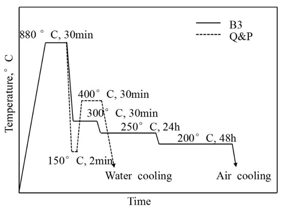
Figure 1.
The schematic illustration of different heat treatments.
A high-speed testing machine (Zwick HTM 5020, ZWICK/ROELL, Ulm, Germany) at strain rates of 0.1, 50, 100, 200, and 500 s−1 was used to carry out the dynamic tensile testing. The dynamic tensile testing setup and the specimen dimensions are shown in Figure 2. Two samples were prepared for each strain rate in order to minimize the error. The deformation of samples is primarily measured by strain gauges attached to the specimen’s deformation parts in the process of testing, as is shown in Figure 2b. The strain gauge positioning was identical for all dynamic tensile test specimens. During the test, a linear displacement transducer (LDT) was used to measure the displacement of the crosshead, and the strain of the specimen was calculated from this acquired displacement. The data synchronous acquisition of dynamic load, displacement, strain and loading rate was performed at a natural frequency of 1 MHz during the dynamic tensile tests.
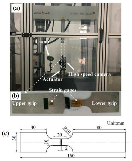
Figure 2.
Dynamic tensile testing setup of (a) Amsler HTM 5020 testing system, (b) Specimen attached with strain gages and (c) Specimen dimensions (unit: mm).
Samples were collected near the fracture along the tensile direction and polished using standard techniques, and then etched in a nital solution (4 vol %) followed by the tensile test. By using an optical microscope (OM, Olympus BM51, Olympus Corporation, Tokyo, Japan), the uniaxial tension samples were selected at different strain rates and subjected to microstructural analysis. In order to observe the tensile fracture morphology and the microstructure near tensile fracture sites, scanning electron microscope (SEM, Nova 400 Nano field-emission, FEI, Hillsboro, OR, USA) and transmission electron microscope (TEM, JEM-2100, JEOL, Tokyo, Japan) were used. The TEM images were conducted to determine the true plate-thicknesses t, by measuring the mean lineal intercept L = πt/2 in a direction normal to the platelength [10]. In order to analyze the carbon content in different microstructures, electron probe micro-analysis (EPMA, JXA-8530F, JEOL, Tokyo, Japan) was used. The acceleration voltage was found to be 15 kV, beam current was found to be 20 mA, and the scanning step was found to be 0.08 μm. The size of the map and spot scanning was 24 × 18 μm2 and 24 μm, respectively. A D/max-2500VL/PC X-ray diffractometer (XRD, Rigaku, Tokyo, Japan) with a Cu Kα radiation was used to determine the austenite (200)γ, (220)γ and (311)γ peaks and the martensite (200)α and (211)α peaks at room temperature [36]. A hardness indenter (Buehler Micromet 5101, Buehler, Lake Bluff, IL, USA) was used to perform Vickers hardness tests. The applied force was reported to be 1.0 kg (9.8 N). Twenty measurements were conducted on each sample, and the corresponding average values are reported in this work.
3. Results
3.1. Original Microstructures
Figure 3a,b show the morphology of the bainite, retained austenite, and martensite in B3 and Q&P specimens. They are constituted of two types of retained austenite, which are blocky and film-like retained austenite. The volume fraction and the size of the retained austenite are different in these two samples. In this study, the blocky retained austenite obtained in the Q&P samples was quite large as compared to that obtained in B3 samples. Figure 3c shows a high magnification of SEM microscopic image of B3 samples. Moreover, it shows that the one-step bainite (with a thickness of 100~300 nm), which is obtained in the first step of the isothermal process, is conventional bainite. The two-step bainite (with a thickness of 50~210 nm) and the three-step bainite (50~100 nm of thickness), which are obtained in the second and third steps of the isothermal process, are nanostructure bainite.
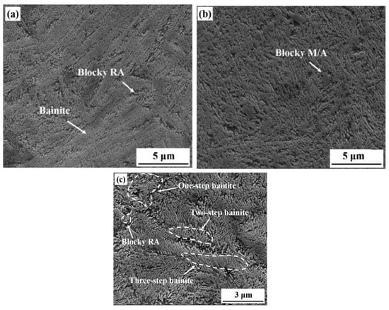
Figure 3.
Scanning electron microscope (SEM) micrographs for samples (a,c) three-step low temperature bainitic transformation (B3) and (b) quenching and tempering (Q&P).
Table 2 presents the measured average size of blocky martensite/austenite (M/A) and the thickness of film-like bainite and martensite, hardness and the volume fraction of retained austenite in each sample. For the B3 samples, the average size of blocky M/A and the thickness of bainite were found to be 500 ± 220 nm and 100 ± 50 nm, respectively. For the Q&P samples, the average size of blocky M/A and the thickness of martensite plates were found to be 2000 ± 450 nm and 500 ± 150 nm, respectively. It is obvious that the average microstructure size obtained in B3 samples was much thinner than that in Q&P samples. Although the total volume fraction of retained austenite was not much different, more blocky M/A was generated in the Q&P samples (an increase from 2.3% to 19.0%) as obtained by the quantitative measurements. It indicates that the B3 process promotes grain refinement. The hardness was considerably larger in the B3 samples than that of the Q&P samples due to the large amount of fine film-like bainite and retained austenite.
Table 2.
The measured average size of blocky martensite/austenite (M/A) and thickness of bainite and martensite, hardness and the volume fraction of retained austenite before and after dynamic tensile testing under the strain rate of 500 s−1 for different heat treatments.
Figure 4 shows the point scanning results of the carbon element with different heat-treated samples. The results are shown by the mean value of the measurement area of the beam spot with a diameter of 1 µm. It is evident that the carbon content in the film-like retained austenite is higher than that of the blocky retained austenite.
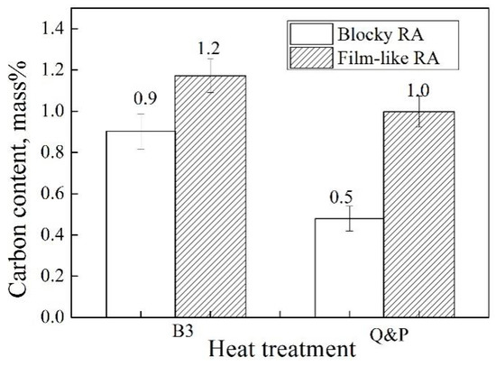
Figure 4.
Carbon content of retained austenite measured by spot scanning in different heat treated samples before dynamic tensile testing.
3.2. Dynamic and Quasistatic Tensile Behavior
The engineering stress-strain curves at quasistatic tension with a strain rate of 0.1 s−1 and at dynamic tension with strain rates of 50, 100, 200 and 500 s−1, respectively, as shown in Figure 5. The results indicate that the tensile strengths of both treatments are improved with an increase in the strain rate. It is also very interesting to note that there is a large gap between the strain rate of 100 s−1 and 200 s−1 for the B3 sample, whereas the large gap exists between the strain rate of 0.1 s−1 and 50 s−1 for the Q&P samples. The ultimate tensile strength (UTS), total elongation (EI), and the product of the tensile strength and the total elongation (UTS × EI) of the samples with varying strain rates are shown in Table 3. The product of tensile strength and elongation is a comprehensive property and is traditionally considered to represent the property of toughness [37]. This indicates that the B3 samples exhibit a better comprehensive property than the Q&P samples.
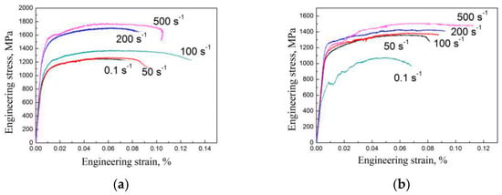
Figure 5.
Engineering stress-strain curves of the quasi-static and the dynamic tensile tests of (a) B3 and (b) Q&P treatment samples.
Table 3.
Dynamic tensile properties of samples with different heat treatments. Ultimate tensile strength (UTS), total elongation (EI), and the product of the tensile strength and the total elongation (UTS × EI).
With a high-speed tensile test at a strain rate of 500 s−1, the volume percentage of retained austenite for the samples of B3 and Q&P processes were 12.3% and 17.6%, respectively (Table 2). The volume fraction decreased by 48.1% for the B3 sample and by 21.4% for the Q&P sample as compared to the initial volume percentage of retained austenite before the tensile test. This result indicated that the martensitic transformation occurs in the B3 and Q&P steels with the decrease of retained austenite. Figure 6 show the bright field (BF) image, dark field (DF) image and the selected area electron diffraction (SAED) pattern of the specimens at a strain rate of 500 s−1 after the dynamic tensile test. After conducting the dynamic tensile test the martensite was identified according to SAED pattern in B3 and Q&P samples. The spots , and , correspond to martensite in Figure 6c,f, respectively. The existence of the retained austenite after the dynamic tensile test is also confirmed near the martensite by the TEM observation, as shown in Figure 6c,f. This finding verifies that the martensite is formed by the strain-induced transformation of the retained austenite during the deformation.
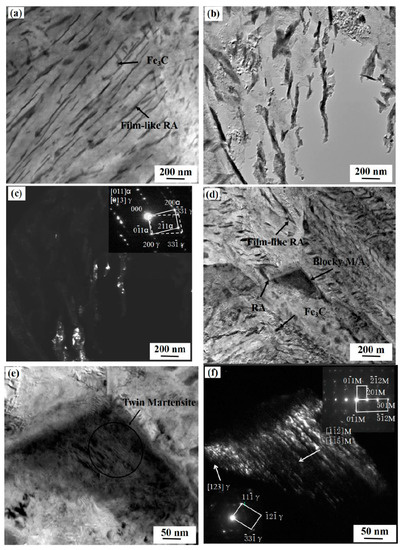
Figure 6.
The transmission electron microscope (TEM) micrographs of (a) morphology, (b) bright field (BF) image and (c) dark field (DF) image and inserted selected area electron diffraction (SAED) pattern of the retained austenite of the B3 specimen at a strain rate of 500 s−1 after the dynamic tensile test; (d) morphology, (e) BF image and (f) DF image and inserted SAED pattern of the retained austenite and the twin martensite of the Q&P specimen at a strain rate of 500 s−1 after the dynamic tensile test.
3.3. Dynamic Tensile Fracture Morphology
The typical SEM fracture morphologies of different heat-treated samples at a strain rate of 500 s−1 are shown in Figure 7. Under the high strain rate conditions, a large number of dimples with different sizes and tearing edges were observed in the B3 sample. This indicates that the material in these regions experienced considerable plastic deformation. More cleavage facets but fewer dimples were observed at Q&P sample at strain rates of 500 s−1. This indicates that the material experienced less plastic deformation. As analyzed above, it can be concluded that the B3 specimen exhibits better ductility.
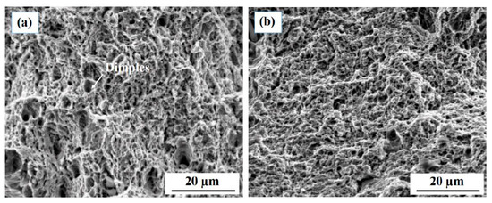
Figure 7.
Typical SEM fracture morphologies of samples (a) B3 and (b) Q&P tested at a strain rate of 500 s−1.
4. Discussion
4.1. Effect of the Carbon Content on the Stability of Retained Austenite
Studies have claimed that film-like austenite contains the higher carbon content than that in blocky austenite [23,24]. They proposed that the morphology change of the retained austenite would have to lead to the carbon redistribution. Consequently, it also caused a change in the chemical stability of the austenite. EPMA was carried out to follow carbon content changes accompanying the morphology change for B3 and Q&P processes. The subsequent measurement also revealed that the carbon content in the film-like austenite is higher than that in blocky austenite (Figure 4). Assuming that all alloying elements except carbon were homogeneously distributed during the slow cooling, isothermal process [21], it is possible to estimate Ms temperature for both high and low carbon austenite by the empirical equation [30]:
From Equation (1), the Ms temperatures for high carbon film-like and low carbon blocky austenite of B3 process are estimated as 39.8 °C and 149.8 °C, respectively. Similarly, they are 116.8 °C and 335.9 °C for Q&P process, respectively. It indicates that the high carbon film-like austenite should be much more stable than the low carbon blocky austenite during deformation. Therefore, the stability of retained austenite in the B3 samples was better as compared to the Q&P samples in this study.
4.2. Effect of the Stability of Retained Austenite on Dynamic Tensile Behavior
The strength of steel primarily depends on its hard phases, such as ferrite, bainite, and martensite, and the plasticity primarily depends on the retained austenite. Retained austenite can have a TRIP effect and increase the strength and plasticity of the steel during the tensile process [38]. The stability of retained austenite is affected by the amount, morphology, and carbon content of retained austenite, and it depends on the strength of the TRIP effect [11,12,13]. The dynamic tensile test of the steel is different from that of the static tensile test, which follows the strain rate hardening effect [39,40] and TRIP effect for retained austenite, and the adiabatic softening effect for martensite [31]. Film-like retained austenite between bainite or martensite laths/plates is helpful. Because the film-like retained austenite has appropriate stability and high dispersion within the bainite matrix and is very beneficial for a steady and gradual martensitic transformation. Hence it can retard the initiation of local strain concentrations and provide a continuous work-hardening effect [34]. However, the blocky retained austenite may play a major role for the initiation of voids and cracks, due to the low stability facilitating an abrupt transformation of retained austenite into martensite [34].
In the present work, the ultimate tensile strength and the total elongation of B3 samples are better as compared with the Q&P samples when the strain rate increases from 0.1 to 500 s−1, as shown in Table 3. The film-like retained austenite has a great effect during the deformation for B3 process. When it was crashed with high-speed strain rate, the film-like retained austenite showed a better TRIP effect and strain rate hardening effect compared to the blocky retained austenite. By comparing the engineering stress and strain curves in Figure 6, it is very interesting to note that the large gap occurred at quite different strain rates for the B3 and Q&P samples. As there is a big gap between the strain rate of 100 s−1 and 200 s−1 for the B3 sample; whereas the large gap exists between the strain rate of 0.1 s−1 and 50 s−1 for the Q&P samples. These results suggest that more unstable blocky retained austenite in the Q&P samples suddenly transformed into martensite under low strain rate, which causes the large gap between the low strain rates. However, for the B3 sample, stable film-like retained austenite showed a good TRIP effect under a higher strain rate. This finding provides an indirect evidence that the film-like retained austenite is more stable than the blocky one.
5. Conclusions
The effects of the carbon content in retained austenite on dynamic tensile properties in nanostructured bainitic steel were investigated. The same experimental tests were performed on those of steels with the same chemical compositions treated by the conventional quenching and partitioning process. The major findings and conclusions can be drawn as follows:
- (1)
- The high carbon film-like austenite was much more stable than the low carbon blocky austenite during deformation.
- (2)
- The nanostructured bainitic steels exhibited the more remarkable dynamic tensile properties due to the better TRIP effect and strain rate hardening effect exhibited by the high carbon film-like retained austenite.
- (3)
- The large gap in engineering stress and strain curves occurred at a higher strain rate (100–200 s−1) for the nanostructured bainitic steels because of the better stability of film-like austenite.
Author Contributions
W.Z. and L.Z. conceived and designed the experiments; C.Z. performed the experiments; W.Z. and L.Z. analyzed the data; K.W. and T.H. contributed reagents/materials/analysis tools; W.Z. wrote the paper.
Funding
This research was funded by [the National Natural Science Foundation of China] grant number [U1532268], [the Major Technology Innovation of Hubei Province] grant number [2016AAA022], [the Nature Science Foundation of Hubei Province] grant number [2016CFA004], the State Key Laboratory of Refractories and Metallurgy (Grant No. 2018QN01) and 111 Project.
Conflicts of Interest
The authors declare no conflict of interest.
References
- Takahashi, M.; Uenishi, A.; Yoshida, H.; Kuriyama, H. Advanced high strength steels for automobile body structures. Mater. Sci. Forum 2007, 539–543, 4386–4390. [Google Scholar] [CrossRef]
- Slycken, J.V.; Verleysen, P.; Degrieck, J.; Bouquerel, J.; Cooman, B.C.D. Crashworthiness characterization and modelling of high-strength steels for automotive applications. Proc. Inst. Mech. Eng. Part D 2006, 220, 391–400. [Google Scholar] [CrossRef]
- Tarigopula, V.; Langseth, M.; Hopperstad, O.S.; Clausen, A.H. Axial crushing of thin-walled high-strength steel sections. Int. J. Impact Eng. 2006, 32, 847–882. [Google Scholar] [CrossRef]
- Peixinho, N.; Jones, N.; Pinho, A. Experimental and numerical study in axial crushing of thin walled sections made of high-strength steels. J. Phys. IV 2003, 110, 717–722. [Google Scholar] [CrossRef]
- Huh, H.; Lim, J.H.; Song, J.H.; Lee, K.S.; Lee, Y.W.; Han, S.S. Crashworthiness Assessment of side impact of an auto-body with 60TRIP steel side members. Int. J. Automot. Technol. 2003, 4, 149–156. [Google Scholar]
- Bhadeshia, H.K.D.H. Nanostructured bainite. Proc. R. Soc. A 2010, 466, 3–18. [Google Scholar] [CrossRef]
- Garcia–Mateo, C.; Caballero, F.G. Ultra-high–strength bainitic steels. ISIJ Int. 2005, 45, 1736–1740. [Google Scholar] [CrossRef]
- Caballero, F.G.; Miller, M.K.; Babu, S.S.; Garcia–Mateo, C. Atomic scale observations of bainite transformation in a high carbon high silicon steel. Acta Mater. 2007, 55, 381–390. [Google Scholar] [CrossRef]
- Caballero, F.G.; Miller, M.K.; Garcia–Mateo, C. Carbon supersaturation of ferrite in a nanocrystalline bainitic steel. Acta Mater. 2010, 58, 2338–2343. [Google Scholar] [CrossRef]
- Garcia-Mateo, C.; Caballero, F.G.; Bhadeshia, H.K.D.H. Development of hard bainite. ISIJ Int. 2003, 43, 1238–1243. [Google Scholar] [CrossRef]
- Morales-Rivas, L.; González-Orive, A.; Garcia-Mateo, C.; Hernández-Creus, A.; Caballero, F.G.; Vázquez, L. Nanomechanical characterization of nanostructured bainitic steel: Peak Force Microscopy and Nanoindentation with AFM. Sci. Rep. 2015, 5, 17164. [Google Scholar] [CrossRef] [PubMed]
- Babu, S.S.; Rohrmann, J.; Misra, R.D.K. Microstructure evolution during tensile deformation of a nanostructured bainitic steel. Scr. Mater. 2013, 69, 777–780. [Google Scholar] [CrossRef]
- Diego-Calderón, I.D.; Santofmia, M.J.; Molina-Aldareguia, J.M.; Monclús, M.A.; Sabirov, I. Deformation behavior of a high strength multiphase steel at macro- and micro-scales. Mater. Sci. Eng. A 2014, 611, 201–211. [Google Scholar] [CrossRef]
- Jacques, P.J.; Furnémont, Q.; Lani, F.; Pardoen, T.; Delannay, F. Multiscale mechanics of TRIP-assisted multiphase steels: I. Characterization and mechanical testing. Acta Mater. 2007, 55, 3681–3693. [Google Scholar] [CrossRef]
- Seol, J.B.; Jung, J.E.; Jang, Y.W.; Park, C.G. Influence of carbon content on the microstructure, martensitic transformation and mechanical properties in austenite/ε-martensite dual-phase Fe–Mn–C steels. Acta Mater. 2013, 61, 558–578. [Google Scholar] [CrossRef]
- Zhang, K.; Zhang, M.; Guo, Z.; Chen, N.; Rong, Y. A new effect of retained austenite on ductility enhancement in high-strength quenching–partitioning–tempering martensitic steel. Mater. Sci. Eng. A 2011, 528, 8486–8491. [Google Scholar] [CrossRef]
- Cui, W.; Gintalas, M.; Rivera-Diaz-del-Castillo, P.E.J. Stability of retained austenite in martensitic high carbon steels. Part II: Mechanical stability. Mater. Sci. Eng. A 2018, 711, 696–703. [Google Scholar] [CrossRef]
- Muránsky, O.; Horňak, P.; Lukáš, P.; Zrník, J.; Šittner, P. Investigation of retained austenite stability in Mn–Si TRIP steel in tensile deformation condition. J. Achiev. Mater. Manuf. Eng. 2005, 14, 26–30. [Google Scholar]
- Tang, Z.Y.; Huang, J.N.; Ding, H.; Cai, Z.H.; Misra, R.D.K. Austenite stability and mechanical properties of a low-alloyed ECAPed TRIP-aided steel. Mater. Sci. Eng. A 2018, 724, 95–102. [Google Scholar] [CrossRef]
- Jimenez-Melero, E.; Dijk, N.H.V.; Zhao, L.; Sietsma, J.; Offerman, S.E.; Wright, J.P.; Zwaag, S.V.D. Characterization of individual retained austenite grains and their stability in low-alloyed TRIP steels. Acta Mater. 2007, 55, 6713–6723. [Google Scholar] [CrossRef]
- Xiong, X.C.; Chen, B.; Huang, M.X.; Wang, J.F.; Wang, L. The effect of morphology on the stability of retained austenite in a quenched and partitioned steel. Scr. Mater. 2013, 68, 321–324. [Google Scholar] [CrossRef]
- Timokhina, I.B.; Hodgson, P.D.; Pereloma, E.V. Effect of microstructure on the stability of retained austenite in transformation-induced-plasticity steels. Metall. Mater. Trans. A 2004, 35, 2331–2341. [Google Scholar] [CrossRef]
- Caballero, F.G.; Miller, M.K.; Clarke, A.J.; Garcia–Mateo, C. Examination of carbon partitioning into austenite during tempering of bainite. Scr. Mater. 2010, 63, 442–445. [Google Scholar] [CrossRef]
- Caballero, F.G.; Garcia-Mateo, C.; Santofimia, M.J.; Miller, M.K.; Andrés, C.G.D. New experimental evidence on the incomplete transformation phenomenon in steel. Acta Mater. 2009, 57, 8–17. [Google Scholar] [CrossRef]
- Jacques, P.J. Transformation-induced plasticity for high strength formable steels. Curr. Opin. Solid State Mater. Sci. 2004, 8, 259–265. [Google Scholar] [CrossRef]
- Bhadeshia, H.K.D.H. Driving force for martensitic transformation in steels. Met. Sci. 1981, 15, 175–177. [Google Scholar] [CrossRef]
- Bhadeshia, H.K.D.H. Steels for bearings. Prog. Mater. Sci. 2012, 57, 268–435. [Google Scholar] [CrossRef]
- Sherby, O.D.; Wadsworth, J.; Lesuer, D.R.; Syn, C.K. Revisiting the Structure of Martensite in Iron-Carbon Steels. Mater. Trans. 2008, 49, 2016–2027. [Google Scholar] [CrossRef]
- Ryu, J.H.; Kim, D.I.; Kim, H.S.; Bhadeshia, H.K.D.H.; Suh, D.W. Strain partitioning and mechanical stability of retained austenite. Scr. Mater. 2010, 63, 297–299. [Google Scholar] [CrossRef]
- Mahieu, J.; Maki, J.; Cooman, B.C.De.; Claessens, S. Phase transformation and mechanical properties of si-free CMnAl transformation-induced plasticity-aided steel. Metall. Mater. Trans. A 2002, 33, 2573–2580. [Google Scholar] [CrossRef]
- Hao, Q.G.; Qin, S.W.; Liu, Y.; Zuo, X.W.; Chen, N.L.; Huang, W.; Rong, Y.H. Effect of retained austenite on the dynamic tensile behavior of a novel quenching-partitioning-tempering martensitic steel. Mater. Sci. Eng. A 2016, 662, 16–25. [Google Scholar] [CrossRef]
- Grajcar, A.; Kuziak, R.; Zalecki, W. Third generation of AHSS with increased fraction of retained austenite for the automotive industry. Arch. Civ. Mech. Eng. 2012, 12, 334–341. [Google Scholar] [CrossRef]
- Hyoung, S.P.; Jong, C.H.; Nam, S.L.; Seol, J.B.; Chan, G.P. Nano-scale observation on the transformation behavior and mechanical stability of individual retained austenite in CMnSiAl TRIP steels. Mater. Sci. Eng. A 2015, 627, 262–269. [Google Scholar]
- Shen, Y.F.; Qiu, L.N.; Sun, X.; Zuo, L.; Liaw, P.K.; Raabe, D. Effects of retained austenite volume fraction, morphology, and carbon content on strength and ductility of nanostructured TRIP-assisted steels. Mater. Sci. Eng. A 2015, 636, 551–564. [Google Scholar] [CrossRef]
- International Organization for Standardization (ISO). Steels-Manual Point Counting Method for Statistically Estimating the Volume Fraction of a Constituent with a Point Grid; ISO 9042; ISO: Geneva, Switzerland, 1988. [Google Scholar]
- Cullity, B.D. Elements of X–ray Diffraction, 2nd ed.; Addison-Wesley Publishing Company Inc.: Boston, MA, USA, 1978; p. 432. [Google Scholar]
- Pereloma, E.V.; Timokhina, I.B.; Miller, M.K.; Hodgson, P.D. Three-dimensional atom probe analysis of solute distribution in thermomechanically processed TRIP steels. Acta Mater. 2007, 55, 2587–2598. [Google Scholar] [CrossRef]
- Tomota, Y.; Tokuda, H.; Adachi, Y.; Wakita, M.; Minakawa, N.; Moriai, A.; Morii, Y. Tensile behavior of TRIP-aided multi-phase steels studied by in situ neutron diffraction. Acta Mater. 2004, 52, 5737–5745. [Google Scholar] [CrossRef]
- Curtze, S.; Kuokkala, V.T.; Hokka, M.; Peura, P. Deformation behavior of TRIP and DP steels in tension at different temperatures over a wide range of strain rates. Mater. Sci. Eng. A 2009, 507, 124–131. [Google Scholar] [CrossRef]
- Oliver, S.; Jones, T.B.; Fourlaris, G. Dual phase versus TRIP strip steels: Microstructural changes as a consequence of quasi-static and dynamic tensile testing. Mater. Charact. 2007, 58, 390–400. [Google Scholar] [CrossRef]
© 2018 by the authors. Licensee MDPI, Basel, Switzerland. This article is an open access article distributed under the terms and conditions of the Creative Commons Attribution (CC BY) license (http://creativecommons.org/licenses/by/4.0/).