Abstract
Surface cracking seriously affects the quality of beam blanks in continuous casting. To study the mechanism of surface crack initiation and propagation under beam blank mesoscopic condition, this study established a polycrystalline model using MATLAB. Based on mesoscopic damage mechanics, a full implicit stress iterative algorithm was used to simulate the crack propagation and the stress and strain of pores and inclusions of the polycrystalline model using ABAQUS software. The results show that the stress at the crystal boundary is much higher than that in the crystal, cracks occur earlier in the former than in the latter, and cracks extend along the direction perpendicular to the force. When a polycrystalline model with pores is subjected to tensile stress, a stress concentration occurs when the end of the pores is perpendicular to the stress direction, and the propagation and aggregation direction of the pores is basically perpendicular to the direction of the tensile stress. When a polycrystalline model with impurities is subjected to force, the stress concentrates around the impurity but the strain here is minimal, which leads to the crack propagating along the impurity direction. This study can provide theoretical guidance for controlling the generation of macroscopic cracks in beam blanks.
1. Introduction
As the raw material of H-beam production, the beam blank has the advantages of fewer rolling passes, high production capacity, low maintenance cost, and high product quality [1,2]. However, because of the complexity of its section, there are often more quality problems than with other blank types [3], particularly surface cracks [4] as shown in Figure 1 and Figure 2 [5]. To meet the new requirements of a new era in terms of the quality of the beam blank and reduce the surface cracks of the billet, it is urgent to conduct in-depth theoretical research on the surface crack propagation mechanism of the billet at different scales, and thus to play a good guiding role in the production of the beam blanks.
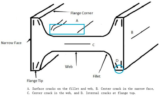
Figure 1.
Cross-section schematic of a beam blank [5].
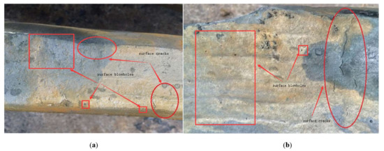
Figure 2.
Surface cracks and blowholes on (a) web and (b) fillet of actual beam blank [5].
At present, the research on cracks of beam blanks has mainly focused on optimizing the process parameters and improving the equipment structure [6,7,8,9,10]. Numerical simulation of crack initiation and propagation of beam blanks remains less studied and the study of the stress concentration effect on the grain interior and boundary is lacking; study of the effects of inclusions and pores on crack initiation and propagation under mesoscopic conditions does not exist. Lasko et al. simulated the crack generation and expansion process of Al2O3/6061 Al composites under different mechanical properties and damage parameters using ABAQUS [11]. Jiang et al. introduced the nodal enrichment functions in the extended finite element method and used the level set method to track the crack propagation path of the compact tension specimen [12]. Wang and Schwalbe studied the transition from intercrystalline to transcrystalline fatigue crack propagation under different ageing conditions of the alloy Cu-35%Ni-3.5%Cr [13]. Shen simulated the crack propagation of the slab under a mesoscopic condition [14]. Xue et al. used the Abaqus program and its user subroutine UVARM to simulate and analyze the single micro-crack mode in a microcosmic view field, and found that the crack propagation form is different with different presetting angles under different stress states; the higher the stress triaxiality value, the more easily the crack propagates, while the crack tends to close when the value is negative. The deformation energy ratio can precisely reflect the influence degree of stress states on crack propagation [15]. The aforementioned literature addresses crack initiation and propagation. Although some of these studies were completed under microscopic observation, the studies of the Q235B beam blank, particularly under the polycrystalline model, were nearly unable to study the effect of inclusions and pores on crack initiation and propagation. The polycrystalline model combined with metallographic experiments is closer to reality, and can do what other model simulations could not do prior. In this study, through the establishment of a polycrystalline model, the crack propagation process in the crystal of a beam blank is analyzed, and the stress and strain conditions with pores or inclusions are also analyzed, providing theoretical guidance for the generation of macroscopic cracks and process optimization.
2. Establishment of a Polycrystalline Model
The polycrystalline model in this study was mainly programmed using MATLAB software (USA). A Voronoi diagram was drawn using the program; its process is shown in Figure 3. The main principle of Voronoi diagram construction is to first randomly generate N points within a certain coordinate range, and then form a triangle with the three points closest to each other, which will generate an infinite number of triangles in the range of coordinates, forming a network. Finally, the midline of the three sides of each triangle in the triangle net is created, and these midlines are connected to form the final polycrystalline model. We termed this method the dual generation method. As can be seen from Figure 4, the polycrystalline model drawn using this method can not only show the irregularity in the size and distribution of grains, but also be consistent in terms of actual grain morphology [16]. Therefore, it is reasonable to draw a polycrystalline model using this method.
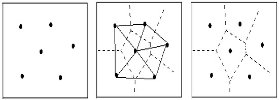
Figure 3.
Implementation process of the Voronoi diagram.
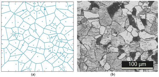
Figure 4.
Grain size diagram of (a) polycrystalline Voronoi diagram in MATLAB and (b) actual grain size of the beam blank.
The coordinates of each point obtained from MATLAB are written into the input file and imported into ABAQUS software (6.12 Abaqus, France) to obtain the polycrystalline model. The size of the model area was 0.1 mm × 0.1 mm, as shown in Figure 5; the related parameters of the Q235B materials in the simulation are shown in Table 1.
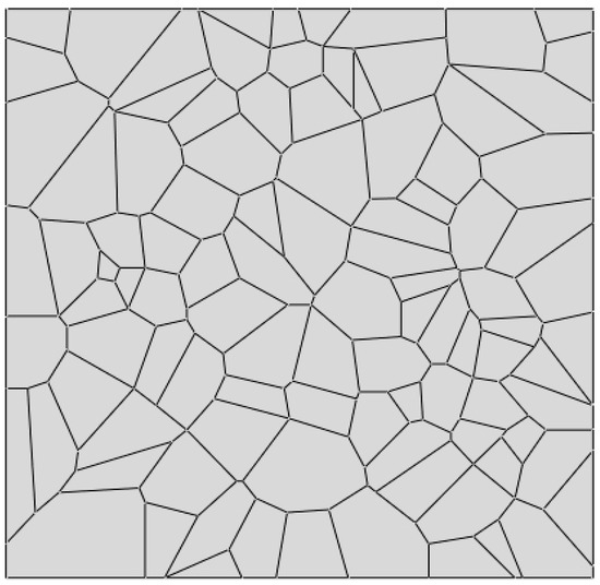
Figure 5.
Two-dimensional polycrystalline model in ABAQUS.

Table 1.
Main parameters used in the simulation.
2.1. Polycrystalline Model with Cracks
Four types of cracks of different angles and different positions were created on the polycrystalline model of the beam blank. The location of the crack was in the grain interior and the grain boundary; the angles between the crack and tensile stress were 15°, 45°, 75°, and 90°. Figure 6 shows the two typical positions of cracks and loading direction into a 45° angle.
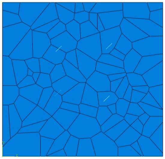
Figure 6.
Crack position distribution diagram of the crack with the tensile stress at an angle of 45°.
2.2. Polycrystalline Model with Pores
During the process of casting the beam blank, the generation of pores is mostly caused by improper protective casting, wet raw materials, poor baking in tundish, poor deoxidization of the liquid steel, and poor degassing in refining [17,18]. The existence of pores will have a great impact on the tensile properties of the materials; therefore, the simulation of the stress and strain of a polycrystalline model with pores is of special significance to prevent the generation of cracks.
Models with pores are mainly created in component modules. When creating the model, material properties such as the elastic modulus and Poisson ratio of the model are assigned to the attribute module, while those with holes are not assigned to properties. Based on the original polycrystalline model, a hole was obtained by cutting into the assembly module, and a model with pores was established to simulate the stress and strain. Figure 7 shows the pores distribution on the polycrystalline model components.
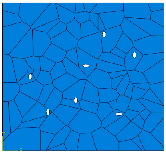
Figure 7.
The distribution of pores on the polycrystalline model components.
2.3. Polycrystalline Model with Inclusions
Inclusions in the billet are typically harder than the matrix, which may cause stress concentration around the impurities, leading to metal damage or fractures. Therefore, the study of a polycrystalline model with impurities has a great effect in reducing cracks in the beam blank.
Models with inclusions were also created in the component module. In the attribute module, the matrix was endowed with corresponding elasticity and plasticity. However, because of the high hardness of the inclusions, it was difficult to produce deformation; thus, only the elastic modulus is provided, which is 100 times the size of the matrix [16]. Based on the original polycrystalline model, inclusions were obtained using an incorporating method in the assembly module. Figure 8 shows the distribution of the inclusions on the polycrystalline model components.
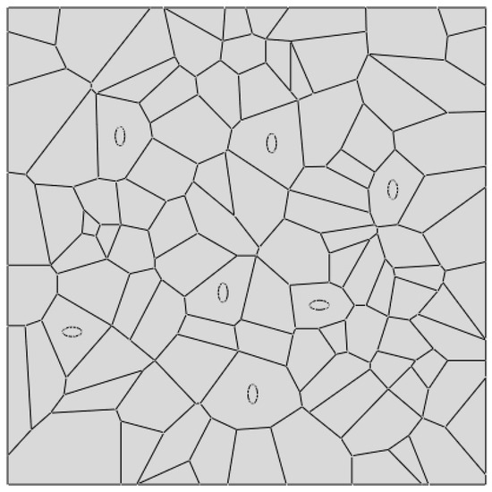
Figure 8.
Inclusions distribution on the polycrystalline model components.
2.4. Meshing and Initial Boundary Conditions
By referring to the relevant data, it was found that during the process of elastoplastic analysis, when the object of the study is an incompressible material, non-coordinated units and linear reduction integral units are mainly used. A linear reduction integral can make the calculation easier and save time. The element type selected using this calculation method in ABAQUS was CPS4R, that is, a four-node bilinear plane stress quadrilateral reduced integration element. The control property of the grid was quadrilateral. In this case, the total number of units in the model was 6562; the meshing of the polycrystalline model is shown in Figure 9.
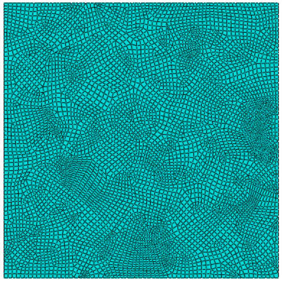
Figure 9.
Meshing of the polycrystalline model.
In this study, the boundary condition set in ABAQUS was to select the displacement/rotation angle, the freedom of the boundary UR3 in the X direction was set to 0, velocity loads were separately applied on both sides, and speed/acceleration was selected with a magnitude of 0.05 m/s and a velocity load in the Y direction of 0 [16]. The boundary conditions can better reflect the actual loading conditions. The specific load is shown in Figure 10.
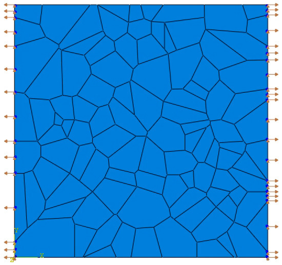
Figure 10.
Load distribution.
3. Analysis of Crack Initiation and Propagation in a Crystal
3.1. Stress and Strain Analysis of Defect-Free Crystals
As can be seen in Figure 11 and Figure 12, in the polycrystalline model without any defect, the stress and strain distribution at the boundary of the polycrystalline model is obviously different from that in the crystal, and the stress and strain at the boundary are obviously greater than those in the crystal. This is because of the interaction of external factors and the grain boundary. For example, under a high temperature condition, the grain boundary will undergo a structural change, which will weaken the grain boundary. Another reason is that the properties of the grain boundary and crystal matrix are quite different. As the tensile stress gradually increases, stress corrosion will first occur at the grain boundary, making the grain boundary more prone to fracturing.
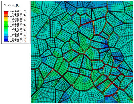
Figure 11.
Stress distribution in the polycrystalline model without defects.
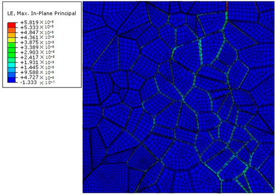
Figure 12.
Strain diagram of the polycrystalline model without defects.
3.2. Analysis of a Polycrystalline Model with Multiple Cracks
Cracks are created at two typical positions with four angles, different from the tensile stress. The two typical positions are the crystal interior and boundary, respectively, at four angles between the crack and tensile stress, namely, 15°, 45°, 75°, and 90°. Figure 13, Figure 14, Figure 15 and Figure 16 show the crack propagation in the two typical positions at different angles from the load direction.
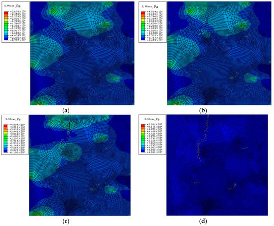
Figure 13.
The (a) first stage, (b) second stage, (c) third stage, and (d) fourth stage of crack propagation with a load direction of 15°.
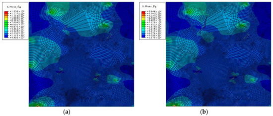
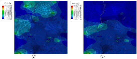
Figure 14.
The (a) first stage, (b) second stage, (c) third stage, and (d) fourth stage of crack propagation with a load direction of 45°.
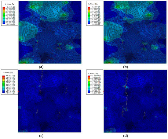
Figure 15.
The (a) first stage, (b) second stage, (c) third stage, and (d) fourth stage of crack propagation with a load direction of 75°.
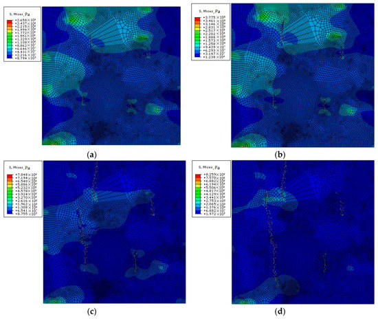
Figure 16.
The (a) first stage, (b) second stage, (c) third stage, and (d) fourth stage of crack propagation with a load direction of 90°.
According to the aforementioned Figure 13, Figure 14, Figure 15 and Figure 16, crack propagation occurs at the crystal boundary prior to that in the crystal, which is a result of crystal interaction that makes the stress at the crystal boundary more concentrated than that in the crystal. Thus, crack propagation is accelerated. Through the analysis of crack propagation under the aforementioned conditions, the following can be found:
- The direction of the crack propagation is basically along with the direction perpendicular to the tensile stress, and the amount of crack propagation along this direction is also the greatest, consistent with the study of Yang et al. [19], Wang and Schwalbe [13].
- The amount of crack propagation at the grain boundary is higher than that in the crystal.
- The angle and tensile stress of the crack are unrelated to the direction of crack propagation, and their influence on crack propagation is mainly reflected in the time and sequence of the crack propagation and the final crack propagation displacement.
3.3. Analysis of a Polycrystalline Model of Different Porosities
Damage to metallic materials when they contain pores can be approximately divided into three processes: first, nucleation occurs around the grain boundary or the second phase particle, then the holes begin to grow, and finally they connect together to form cracks. Therefore, it is of great significance to study the stress and strain process of a polycrystalline model with holes to show the mechanism of crack formation.
Figure 17 shows the stress distribution of the polycrystalline model with different porosities, from which certain regularity can be found in pores. In the direction perpendicular to tensile stress, the maximum stress can be observed at the end of pores; while in the same direction of the force, the minimum stress and strain can be calculated around other pores with insignificant deformation. It indicates that when the polycrystalline model deforms, stress concentration at the end of the pores is mostly perpendicular to the direction of tensile stress.
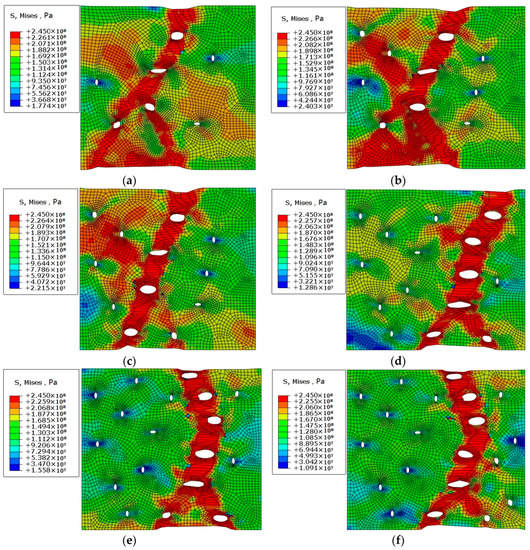
Figure 17.
Stress distribution diagram of a polycrystalline model with different porosity of (a) 0.40%, (b) 0.60%, (c) 0.75%, (d) 0.90%, (e) 1.10%, and (f) 1.30%.
Figure 18 shows the strain results of polycrystalline models when the porosity is 0.4% and 1.3%, respectively. It can be found from the variation diagram of strain that the plastic strain is more concentrated around the pores than the matrix, and the polycrystalline model with a porosity of 1.3% is significantly larger than the polycrystalline model with a porosity of 0.4%, which indicates that the effects of different porosity on metal damage are different. At the same time, under different porosity, the pores begin to propagate and aggregate in the direction perpendicular to the tensile stress. The main reason for this phenomenon is that in the direction perpendicular to the tensile stress, the stress concentration occurs at the end of the pores, which resulting in larger equivalent plastic strain around the pores, and the localization of the strain results in continuous aggregation and propagation of the pores, so the crack always starts from this direction.
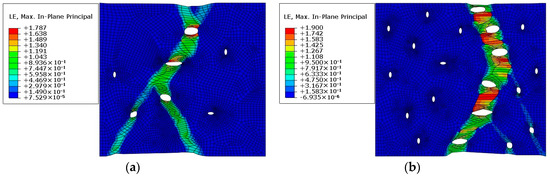
Figure 18.
Tensile strain diagram with porosity of (a) 0.4% and (b) 1.3%.
3.4. Analysis of Polycrystal Model with Different Proportion Inclusions
The size and number of inclusions in steel is not only an important condition to evaluate steel quality, but also one of the main factors causing defects, and is the unavoidable existence in steel materials. Because the properties of the inclusions are different from the properties of the steel matrix materials, it has a great influence on the deformation and fracture process of the steel materials. In this paper, the stress and strain behavior of polycrystalline model with different percentage of inclusions is simulated to analyze its effect on material failure.
On the polycrystalline model parts, different proportion areas are divided as inclusions, and then inclusions material properties are given in the property module. Because it is a hard phase relative to the matrix of the polycrystalline model, only elastic properties are assigned to it. In this method, models with 0.44%, 0.57%, 0.70%, and 0.82% percentage of impurities were created respectively, and the same boundary conditions were set for simulation. Figure 18 shows the stress distribution in matrix with inclusions. As can be seen from the figure, the stress mainly concentrates at the inclusions, and the stress at the inclusions is much larger than that at the matrix. The reason for this phenomenon is that the elasticity and plasticity differences between impurities and the matrix are relatively large in the polycrystalline model. When the polycrystalline model is under stress, impurities can hardly meet the deformation requirements when the matrix deforms. Therefore, the impurities cannot deform simultaneously with the matrix, as a result, the stress accumulates in and around impurities, making the stress distribution at the impurities more obvious. Combined with Figure 17 and Figure 19, it can be seen that the influence of pores on the crack is greater than that of inclusions.
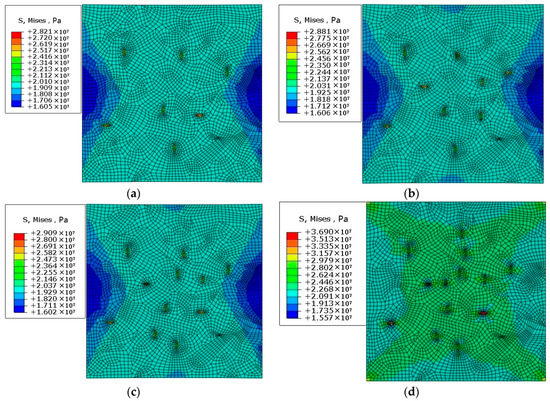
Figure 19.
Stress distribution diagram of a polycrystalline model with different impurity percentages of (a) 0.44%, (b) 0.57%, (c) 0.70%, and (d) 0.82%.
As can be seen from the strain of a polycrystalline model of different impurity percentages in Figure 20, the deformation of the matrix of the polycrystalline model is much different from that of the impurities; the deformation of the impurities is much less than that of the matrix. This is because of the large differences in the elasticity and plasticity of the impurities and polycrystalline matrix. After the loading is applied, the impurity cannot deform because of its properties; thus the stress concentration will occur around the impurity and the stress value will be increasingly greater, resulting in the separation of the impurity and the matrix, and thus a hole. Therefore, when a metal material is subjected to a large external force, the crack will often expand along the direction of the impurities, resulting in the material damage and fracture.
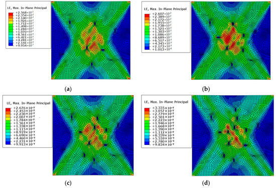
Figure 20.
Strain distribution diagram of a polycrystalline model with different impurity percentages of (a) 0.44%, (b) 0.57%, (c) 0.70%, and (d) 0.82%.
4. Conclusions
In this study, a polycrystalline model of a beam blank was established using MATLAB. Based on mesoscopic damage mechanics, the full implicit stress iterative algorithm was used to simulate the crack propagation of the polycrystalline model using ABAQUS software, as well as a stress and strain simulation of a polycrystalline model with pores and impurities. The conclusions are as follows:
- The stress at the crystal boundary is much greater than that in the crystal after loading on the defect-free polycrystalline model.
- Crack propagation occurs at the crystal boundary prior to that in the crystal, and the propagation of the former is greater than that of the latter.
- The direction of crack propagation is basically along the direction perpendicular to the tensile stress, and the amount of crack propagation along this direction is also the greatest.
- When a polycrystalline model with pores is subjected to tensile stress, stress concentration occurs at the position where the end of pores is perpendicular to the stress direction, and the propagation and aggregation direction of the pores are basically perpendicular to the direction of the tensile stress. When the pores ends are parallel to the stress direction, the stress values at these locations are relatively small.
- When a polycrystalline model with impurities is subjected to a force, a large stress concentration will occur at the impurities, while the strain generated by the impurities is the smallest. This often causes the crack to propagate along the direction of the impurities, thus causing damage to and fracturing of the material.
- Both inclusions and pores affect crack initiation and propagation. Through mesoscopic simulation, it was found that the influence of pores on cracks is greater than that of inclusions.
- The simulation of mesoscopic crack initiation and propagation of a beam blank can provide theoretical guidance for the generation of macrocracks and process optimization.
Author Contributions
W.C. and L.Z. conceived and designed the experiments and research ideas; G.Y., G.G., and B.H. performed the experiments, the simulations, the early stage of the investigation, and the data collection; W.C. and G.Y. analyzed the data and graphics; W.C. and L.Z. supervised the whole work; G.Y. wrote and revised the paper.
Funding
This research was funded by the National Natural Science Foundation of China (51574103 and 51574106).
Acknowledgments
The authors would like to thank the technical support of Hebei Engineering Research Center of High Quality Steel Continuous Casting.
Conflicts of Interest
The authors declare no conflict of interest.
References
- Xu, M.G.; Zhu, M.Y. Transport Phenomena in a Beam-Blank Continuous Casting Mold and a New Design of Submerged Entry Nozzle. ISIJ Int. 2015, 55, 791–798. [Google Scholar] [CrossRef]
- Xu, H.L.; Wen, G.H.; Sun, W.; Wang, K.Z.; Yan, B. Analysis of thermal behavior for beam blank continuous casting mold. J. Iron Steel Res. Int. 2010, 17, 17–22. [Google Scholar] [CrossRef]
- Lee, J.E.; Yeo, T.J.; Kyu Hwan, O.H.; Yoon, J.K.; Yoon, U.S. Prediction of cracks in continuously cast steel beam blank through fully coupled analysis of fluid flow, heat transfer, and deformation behavior of a solidifying shell. Metall. Mater. Trans. A 2000, 31, 225–237. [Google Scholar] [CrossRef]
- Xu, H.L. Simulation and Optimization of Cooling Process for Continuous Casting Beam Blank. Ph.D. Thesis, Chongqing University, Chongqing, China, 2010. [Google Scholar]
- Yang, G.Y.; Zhu, L.G.; Chen, W.; Yu, X.W.; He, B.M. Initiation of Surface Cracks on Beam Blank in the Mold during Continuous Casting. Metals 2018, 8, 712. [Google Scholar] [CrossRef]
- Lv, M.; Lu, B.; Wang, X.X.; Shan, Z.G.; Zhang, Q.; Chen, Y.S. Research and control on web plate crack of the large type beam blank. Iron Steel 2010, 45, 99–102. [Google Scholar] [CrossRef]
- Wu, J.; Xu, W.; Yang, Y.D. Technics study of reduing longitudinal surface crack of beam blank. Iron Steel 2009, 45, 95–97. [Google Scholar] [CrossRef]
- Xu, H.L.; Wen, G.H.; Sun, W.; Wang, K.Z.; Yan, B.; Luo, W. Thermal behaviour of moulds with different water channels and their influence on quality in continuous casting of beam blanks. Ironmak. Steelmak. 2013, 37, 380–386. [Google Scholar] [CrossRef]
- Du, Y.P.; Yang, J.W.; Shi, R.; Cui, X.C. Effect of submerged entry nozzle (sen) parameters and shape on 3-d fluid flow in mould for beam blank continuous casting. Acta Metall. Sin. 2004, 17, 705–712. [Google Scholar]
- De Santis, M.; Cristallini, A.; Rinaldi, M.; Sgrò, A. Modelling-based innovative feeding strategy for beam blanks mould casting aimed at as-cast surface quality improvement. ISIJ Int. 2014, 54, 496–503. [Google Scholar] [CrossRef]
- Lasko, G.; Weber, U.; Schmauder, S. Finite Element Simulations of Crack Propagation in Al2O3/6061 Al Composites. Acta Metall. Sin. 2014, 27, 853–861. [Google Scholar] [CrossRef]
- Jiang, Z.W.; Wan, S.; Cheng, C. Analysis of the Crack Propagation Based on Extended Finite Method. Appl. Mech. Mater. 2013, 275–277, 169–173. [Google Scholar] [CrossRef]
- Wang, G.X.; Schwalbe, K.H. A study of the transition from intercrystalline to transcrystalline fatigue crack propagation in different ageing conditions of the alloy Cu-35%Ni-3.5%Cr. Int. J. Fatigue 1993, 15, 3–8. [Google Scholar] [CrossRef]
- Shen, J.L. Study on Simulation of Surface Cracks Growth for Continuous Casting Q235 Slab. Mater’s Thesis, Chongqing University, Chongqing, China, 2013. [Google Scholar]
- Xue, F.M.; Li, F.G.; Li, J.; He, M.; Yuan, Z.W.; Wang, R.T. Numerical modeling crack propagation of sheet metal forming based on stress state parameters using xfem method. Comput. Mater. Sci. 2013, 69, 311–326. [Google Scholar] [CrossRef]
- Wang, F.G. Crack Initiatiation and Propagation of Duplex Stainless Steel Finite Element Simulation. Master’s Thesis, Xi’an Technological University, Xi’an, China, 2014. [Google Scholar]
- Chen, L.Y.; Zhu, Y.C. Cause for bubbles occurring in top CC slab & countermeasures. Contin. Cast. 1999, 2, 19–20. [Google Scholar] [CrossRef]
- Geng, M.S.; Wang, X.H.; Zhang, J.M.; Wang, W.J.; Liu., Z.M. Study of Surface Blow Hole Defects of Continuous Casting Slab. Iron Steel 2010, 45, 45–50. [Google Scholar] [CrossRef]
- Yang, G.Y.; Zhu, L.G.; Chen, W.; Yu, X.W.; Guo, G.X. Propagation of Surface Cracks on Beam Blank in the Mould during Continuous Casting. Ironmak. Steelmak. 2018. [Google Scholar] [CrossRef]
© 2018 by the authors. Licensee MDPI, Basel, Switzerland. This article is an open access article distributed under the terms and conditions of the Creative Commons Attribution (CC BY) license (http://creativecommons.org/licenses/by/4.0/).