Abstract
With readily available and ever-increasing computational resources, the modelling of continuous casting processes—mainly for steel, but also for copper and aluminium alloys—has predominantly focused on large-scale numerical simulation. Whilst there is certainly a need for this type of modelling, this paper highlights an alternative approach more grounded in applied mathematics, which lies between overly simplified analytical models and multi-dimensional simulations. In this approach, the governing equations are nondimensionalized and systematically simplified to obtain a formulation which is numerically much cheaper to compute, yet does not sacrifice any of the physics that was present in the original problem; in addition, the results should agree also quantitatively with those of the original model. This approach is well-suited to the modelling of continuous casting processes, which often involve the interaction of complex multiphysics. Recent examples involving mould taper, oscillation-mark formation, solidification shrinkage-induced macrosegregation and electromagnetic stirring are considered, as are the possibilities for the modelling of exudation, columnar-to-equiaxed transition, V-segregation, centreline porosity and mechanical soft reduction.
1. Introduction
Continuous casting is a process whereby molten metal is solidified into semi-finished billets, blooms, slabs or strips for subsequent rolling in finishing mills; it is the most frequently used process to cast not only steel, but also aluminum and copper alloys, with the main configurations being as shown in Figure 1. Although originally a process that was developed on an industrial scale in the early decades of the 20th century for the casting of non-ferrous alloys, its use has been widespread also for steel since the 1950s. Compared to casting in moulds, continuous casting is more economical, as it consumes less energy and produces less scrap. Furthermore, the properties of the products can be easily modified by changing the casting parameters. As all operations can be automated and controlled, continuous casting offers numerous possibilities to adapt production flexibly and rapidly to changing market requirements and to combine it with digitization technologies. Nevertheless, new challenges continuously arise, as ways are sought to minimize casting defects and to cast new alloys.
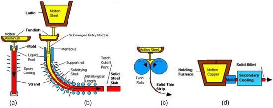
Figure 1.
Continuous casting: (a) vertical; (b) curved; (c) strip; and (d) horizontal. Reproduced with permission from Brian G. Thomas, 2018 [1].
An important aspect in meeting these challenges is the use of modelling and simulation, as reviewed recently for the case of steel in [2]. With readily available and ever-increasing computational resources, the majority of modelling and simulation activity for continuous casting processes focuses on large-scale numerical simulation. Whilst there is certainly a need for this type of modelling, the focus in this paper is on an alternative approach more grounded in applied mathematics, asymptotic methods in particular, which lies between overly simplified analytical models and multi-dimensional simulations. In this approach, the governing equations are nondimensionalized and systematically simplified to obtain a formulation which is numerically much cheaper to compute, yet does not sacrifice any of the physics that was present in the original problem; in addition, the results should agree also quantitatively with those of the original model. This approach is well-suited to the modelling of continuous casting processes, which often involve the interaction of complex multiphysics.
There are several motivations for this hybrid asymptotic/numerical approach. The first is that it has been applied successfully in other areas of science and technology, as witnessed by the growth of an activity known as practical asymptotics [3,4,5,6,7,8]; note, however, that this is not identical to the model order-reduction approach [9], which is also prevalent in industrial mathematics. The second is the Moore’s law effect in modelling [10]: namely, that, although computational power doubles every 18 months, it will still be many years before all the length scales in a casting process will be numerically resolved [11]. Moreover, although the use of asymptotic methods for the modelling of continuous casting is not unknown, it remains somewhat limited to fluid flow and heat transfer aspects [12,13,14,15,16,17,18,19,20]. Thus, the goal here is to review recent activity in this area, based primarily on the activities of the author and co-workers [21,22,23,24,25,26,27,28,29,30,31,32,33].
The layout of the paper is as follows. Section 2 focuses on models for the determination of metallurgical length. Section 3 is on the role of the air gap and implementation of mould taper. Section 4 focuses on oscillation-mark formation in the continuous casting of steel, whereas Section 5 is on solidification shrinkage-induced macrosegregation. Section 6 is on electromagnetic stirring, with conclusions being drawn in Section 7. Finally, Appendix A shows in more detail how the practical asymptotics approach is applied to one of the sub-problems considered in the paper.
2. Metallurgical Length
2.1. Pure Metals or Eutectic Alloys
To be able to correctly dimension a continuous casting process, it is of primary importance to have an estimate of where complete solidification will occur. This requires a model that takes into account fluid flow, heat transfer and phase change; a generalized two-dimensional (2D) schematic for this is shown in Figure 2. The inlet drawn here does not correctly reflect the situation in all continuous casting processes. For example, for the continuous casting of steel blooms or billets, a submerged entry nozzle is used, whereas, for the strip casting of copper and its alloys, multiple jets are located above the molten metal surface. For the latter, a 2D model was considered in [34,35] which employed the k- model to describe the turbulent flow of molten metal; in addition, experimental measurements were carried out to obtain data necessary for modelling the heat transfer between the solidified copper shell and the surrounding cooling mould. The resulting equations were solved using the commercial software CFX [36]. In much later work [21], the original model equations were reconsidered in the light of a much simpler model which simply took account of the streaming of the melt at the casting speed, through asymptotic reduction, the original 2D time-independent model becomes effectively a 1D time-dependent, model, with the usual understanding that the coordinate in the casting direction corresponds to the product of and time, if the casting geometry is slender. Moreover, since the original model was for an almost pure copper melt, the simpler model was formulated in terms of a sharp interface between liquid and solid phases [21]; this approach would also be suitable for eutectic alloys.
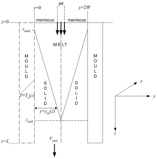
Figure 2.
Schematic of a vertical continuous casting process.
Figure 3 shows a comparison of the key results from [21,34,35]. Thus, although significantly more computational effort was required in generating the results in [34,35], there is scant difference between them. Whilst this may be due to the limited effects of turbulence lower down in the caster, it is notable that all quantities agree well even near the top, where the effects of turbulence should still be quite strong.
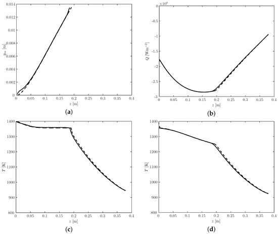
Figure 3.
Comparison of: (a) the location of the solidification front, ; (b) the heat flux, Q, at the outer edge of the copper strip; (c) the temperature at the centreline (); and (d) the temperature at the outer edge of the copper strip. In all cases, the solid line is for the full model, and the dashed line is for the reduced model; z denotes the distance along the casting direction from the meniscus. Reproduced from [21], with copyright permission from Elsevier, 2017.
2.2. Alloys
In general of course, the alloys that are cast have a substantial solidification interval, leading to the formation of a mushy zone between the melt and the solid, in which both coexist; thus, the situation is now more akin to Figure 4 than Figure 2. Typically, the numerical solution of the governing equations is handled by introducing an auxiliary variable, commonly the local liquid fraction, and using an enthalpy formulation on a fixed grid [37,38,39,40,41]. This generally functions well enough if a basic description of fluid flow and heat transfer is required—all the more so if the solidification interval of the alloy is large. However, it is often required to determine quantities that affect the quality of the final solidified alloy, such as the degree of macrosegregation of an alloy’s solute elements, the ratio of equiaxed-to-columnar crystals or the thermomechanical stress; all of these are associated with processes in the mush. Thus, to compute all of these quantities accurately in the region where they really matter, it would be convenient to be able to resolve the locations of the solid-mush and mush-liquid interfaces explicitly.
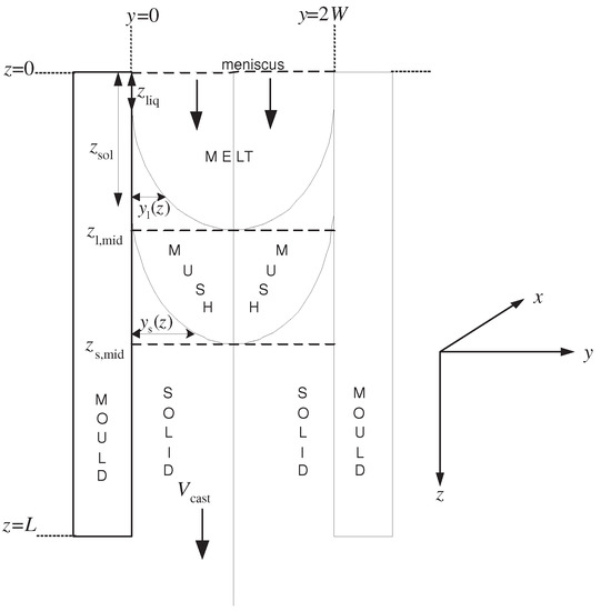
Figure 4.
2D schematic of the vertical continuous casting of an alloy.
The methodology to address this situation for the case of continuous casting processes was developed in [22]. This was done by applying a boundary immobilization method for the solidus and liquidus isotherms, transforming from () to () variables, as shown in Figure 5, with given by
where and denote the locations of the liquidus and solidus isotherms, respectively. A benchmark problem was solved using three different formulations:
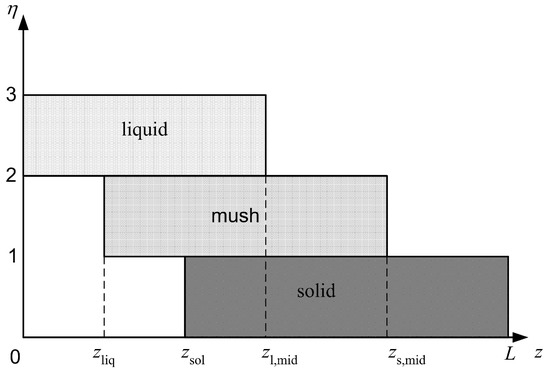
Figure 5.
Computational domain in () variables.
- (A)
- an enthalpy-like formulation just mentioned using the full 2D time-independent equations;
- (B)
- an enthalpy-like formulation using a reduction of the full 2D time-independent equations to a 1D transient-like formulation of the type used in [21];
- (C)
- the proposed new formulation, which is also 1D transient-like but resolves the locations of the solidus and liquidus isotherms explicitly.
The key results are summarized in Figure 6. Figure 6a–f shows, respectively, the location of the liquidus isotherm (), the location of the solidus isotherm (), the mould wall temperature, the heat flux at the mould wall, the centreline temperature and the temperature gradient in the casting direction at the centreline, and indicates that the novel formulation gives results that agree very well with those of the more conventional formulations and . In future, it is therefore hoped to extend this formulation for modelling the multiphysical phenomena that are present in the mushy zone, as mentioned above.
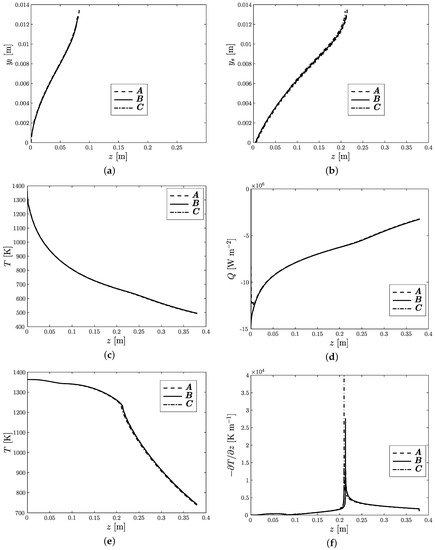
Figure 6.
(a) The location of the liquidus isotherm, ; (b) the location of the solidus isotherm, ; (c) mould wall temperature; (d) mould wall heat flux, Q; (e) centreline temperature; and (f) at the centreline. All quantities are given as functions of z. Reproduced from [22], with copyright permission from Elsevier, 2017.
3. Air Gap and Mould Taper
In the models presented thus far, heat transfer between the solidified shell and the mould wall is characterized by an experimentally measured heat transfer coefficient and the surface of the mould wall is assumed to be parallel to the casting direction. In practice, however, it is thought that an air gap forms between the mould wall and the solidified shell when the latter, in going from a plastic to elastic state, is strong enough to withstand the metallostatic pressure of the adjacent molten metal, thereby receding from the mould as a result of contraction; a contributing factor is also thought to be the expansion of the mould itself. Air-gap formation prohibits effective heat transfer between the mould and shell, leading to longer solidification lengths and requiring supplementary process design considerations, such as mould tapering. Consequently, the actual situation is more similar to that shown in Figure 7, which shows the idea for the case of the casting of pure metal or eutectic alloy. Now, in addition to determining the location of the solid/melt interface, it is also necessary to determine the location where the air gap begins to form, denoted by as well as the width of the air gap as a function of given in the figure as
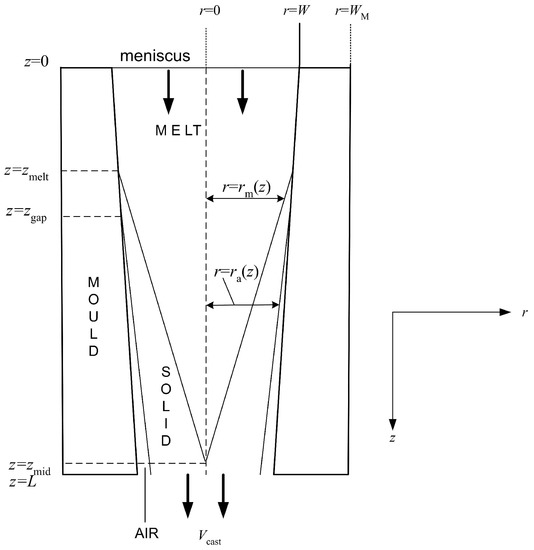
Figure 7.
A 2D schematic of the continuous casting process with tapered mould walls and superheat.
Early analytical models made preliminary headway on the air gap problem [42,43,44,45]. Later papers have been solely numerical studies [46,47,48,49,50,51,52]. In the latter, the common approach is to employ multidimensional finite element models to describe the coupled thermomechanical interaction that occurs between the solidified shell and the mould wall. However, in contrast to all of these, in [24,25,26,27], the fact that the air gap is slender was used, together with the generalized plane strain approximation, to derive an asymptotic model for the aforementioned interaction in the case of an untapered mould; in particular, closed-form expressions can be found for the stress and strain components. Ultimately, the only numerical burden is the computation of a moving boundary problem for the temperature, although with back-coupling to the structure mechanical problem via the boundary conditions; the case of a tapered mould fits easily into this framework, since the taper is always small enough to be amenable to asymptotic methods: for example, in the case of steel casters, the taper is usually of the order of 2%/m [47].
In [28,29], the interplay of melt superheat and mould taper was considered for an axisymmetric continuous casting geometry, although we just focus on the effect of mould taper itself for one particular value of superheat here. Figure 8a shows the different taper profiles considered; here, M is a dimensionless parameter related to the actual mould taper, in per cent/m, by
where
where is the thermal expansion coefficient of the metal and is an appropriate temperature scale for the problem (see [28,29] for exact details). Figure 8b–d shows, respectively, how the position of the solid/air interface (), the position of the solid/air interface () and the width of the air gap, : vary with z for different values of M. Lastly, Figure 9 gives an idealized result: the minimum taper necessary to avoid any air gap at all, with Figure 8b also showing the profile for denoted there by that this would correspond to. However, in Figure 9, a taper profile that is much more extreme than those currently in use would be required.
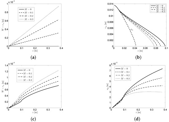
Figure 8.
Dependence on M of: (a) the taper profile, , relative to W; (b) the position of the solid/air interface, ; (c) the position of the solid/air interface, ; and (d) the width of the air gap, .
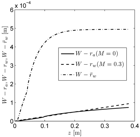
Figure 9.
Comparison of the size of the air gap for the untapered system (solid line) with the linear taper (dotted line), and the ideal taper required to completely eliminate the air gap (dashed line).
Finally, we note that, although the results in Figure 8 and Figure 9 are for a somewhat fictitious situation, work is nevertheless underway to extend the results to the more realistic case of the continuous casting of round steel billets; a good source for validating the approach will be the experimental and theoretical results in [47]. A further future extension would then be for mould taper for blooms, billets and slabs, in which the generalized plane strain approximation can also be used, as well as the fact that the air gap is slender and the taper is small enough for asymptotic methods to be applicable.
4. Oscillation-Mark Formation
Although the continuous casting configurations shown in Figure 2, Figure 4 and Figure 7 indicate a mould that is stationary, in reality, it is made to oscillate in the casting direction; this is particularly so for the continuous casting of steel. Moreover, a mould powder, often termed flux, is introduced over the steel melt; the powder becomes molten and the flows between the steel and the oscillating mould, with the resulting configuration being as in Figure 10, which depicts the initial stages of solidification in continuous casting. In this way, solidified steel is prevented from contacting the mould directly and resolidified flux is shaken from the surface of the mould. However, as is well-known and hinted at in Figure 10, a detrimental effect of this construct is the formation of depressions on the surface of the solidified steel, commonly referred to as oscillation marks; an experimental example is shown in Figure 11. Moreover, although the mould oscillation is normally periodic in time, this does not in general mean that the marks which form are identical and periodically spaced. For example, Figure 12 shows the spacing between thirteen marks, also termed as the pitch, taken from a continuously cast steel sample, from which it is clear that, more often than not, the pitch obtained was close to the average value. This may in itself not be noteworthy, other than that this average value is also close to the theoretical value, as we show below. Further samples of experimental oscillation-mark data, arguably the largest ever collected from a single continuous casting process, can be found in [53,54].
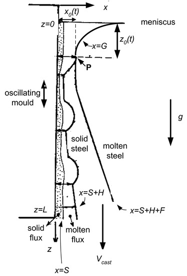
Figure 10.
A sketch showing how an oscillation mark forms.
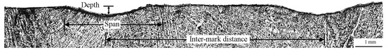
Figure 11.
Two adjacent oscillation marks and typically observed microstructure underneath them.
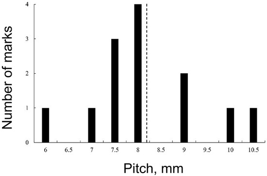
Figure 12.
Experimental results showing the number of marks associated with a given pitch, taken from [30]. The vertical dashed line shows the average value.
Oscillation marks have been subject of modelling in the continuous casting literature since the early 1980s [55], with the most recent review being given in [56]. At the centre of this modelling is the need to relate it to the early experimental work of Tomono [57], which classified oscillation marks as being either of overflow-type, in which case the solidified shell is strong enough to avoid deformation, causing the steel meniscus to overflow the solid tip, or fold-type, in which case the solid shell is too thin to prevent its tip from bending back under the rim pressure. Recent attempts at modelling this problem have tended towards the use of computational fluid dynamics [56,58,59,60,61], although results which give either fold or overflow marks remain elusive, as is a criterion, in terms of process parameters, for when one or the other should occur.
In this context, Vynnycky et al. [30] recently revisited an earlier model for oscillation-mark formation by Hill et al. [18], with a view to providing a detailed and systematic asymptotic analysis; the model used lubrication theory coupled to heat conduction in the solid flux, molten flux and solid steel regions, and was able to predict the oscillation-mark shape. This resulted in a model involving fifteen dimensionless parameters which was able to give good agreement with the experimental oscillation-mark profiles shown in Figure 11; the comparison is shown in Figure 13. Note that the pitch in this figure is given by where f is the mould oscillation frequency, and that this is close to the dashed line in Figure 11 for the values ms and s used in [30,53]. Furthermore, the profiles and the character of the model, which neglects the presence of the meniscus completely, indicated that the marks were of fold-type.
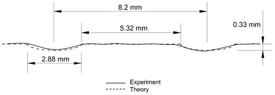
Figure 13.
Comparison of the theoretically calculated oscillation mark profiles and those measured experimentally by Saleem [53].
In further work [32], an attempt was made to extend the model to include the effect of the meniscus, thereby allowing the possibility of model parameters to drive whether the model predicts fold-type or overflow-type marks. For this purpose, a novel “ moving-point” formulation was derived, which unlike the volume-of-fluid (VOF) formulation adopted in [56,58,59,60,61], attempts to track explicitly the location of the point at which solidification first begins. This approach suggests that if solidification has not occurred within a capillary length from the top of the meniscus, then the meniscus profile predicted by Bikerman [62], and which emerges naturally in the asymptotic analysis in [32], will collapse, leading to overflow; however, further work is required to extend the isothermal model derived in [32] to determine where the temperature first becomes low enough for the steel to start to solidify.
5. Macrosegregation
Macrosegregation is the term used to denote to variations in composition that occur in alloy castings or ingots and range in scale from several millimetres to even metres; it is a central problem, since it strongly influences the further workability of the cast products and their mechanical properties. As was already well-established as early as the 1960s [63,64], it arises as a consequence of the nature of the solidification process for alloys, which involves the formation of a mushy network of solid dendrites through which there is the slow flow of interdendritic melt, and the transport of alloying elements. In particular, as solidification occurs, if the solute—for example, Cu in an Al-4.5 wt% Cu alloy [65] or Sn in a Cu-8 wt% Sn alloy [66]—is more soluble in the liquid phase than it is in the solid phase, then it is rejected into the melt, resulting in a non-uniform distribution of solute in the final solidified casting.
Over the years, there has developed a substantial body of modelling work on macrosegregation in one-dimensional transient solidification [67,68,69,70,71,72], some of which is of relevance to steady-state continuous or direct chill casting processes. In higher dimensions, computational fluid dynamics (CFD) is often used, although, as indicated in [73], numerical dispersion and diffusion are present in the simulated macrosegregation profiles reported in the literature, hindering the interpretation of CFD results. In particular, it has been found that unstructured computational meshes can eliminate the numerical dispersion that is present when structured meshes are used; however, undesirable numerical diffusion is introduced instead. On the other hand, refining a structured mesh alleviates problems with numerical oscillations, but instead results in a dramatic increase in computation time [74]. More details on recent efforts to come to grips with these difficulties can be found in [73,75,76,77,78,79].
One particular cause of macrosegregation in continuous casting is due to solidification shrinkage, which tends to dominate that due to natural convection induced by thermal and solutal gradients. The modelling of this phenomenon is particularly amenable to asymptotic methods since the macrosegregation is driven by a dimensionless parameter, that is often no greater than around 0.1; here, and are the solid and liquid densities, respectively. Consequently, the resulting non-uniform solute profile can be obtained as the second term in a regular perturbation series in As a result, and as shown in [23], there is therefore no need to resort to CFD to compute the Darcy-damped Navier–Stokes equations for modelling the melt and the mushy zone. Although the analysis is algebraically somewhat lengthy, the computational load is not; moreover, because of the hybrid analytical-numerical method used, there is no possibility for any numerical diffusion or dispersion. The situation considered in [23] is similar to that in Figure 4, although with no superheat, so that there is only a mushy zone and a fully solidified region. Moreover, the lever rule is assumed for microsegregation at the microscale, and it is demonstrated analytically that the leading-order solute at the macroscale is also given by the lever rule.
The results of the approach were compared with those obtained in [80] using CFD for the continuous casting of an Al-4.5 wt% Cu alloy, and are shown in Figure 14. Several features are noteworthy in this figure. First, we see so-called inverse segregation at : this is the well-established phenomenon wherein the solute concentration is higher at the outer surface of the casting than it is elsewhere [65,74,81]. Moreover, near we would expect to see negative segregation, i.e., the concentration would be less than the initial composition. Note that two curves have been included from [80]: one using the linearized phase diagram for the Al-Cu system, and one using the non-linearized phase diagram. As can be seen, the agreement with the results of the asymptotic model is very reasonable for m, although rather less so thereafter. This could be due to a variety of factors:
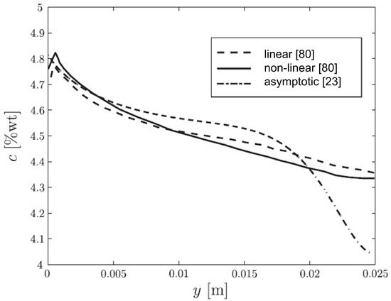
Figure 14.
Comparison of the macrosegregation profiles obtained in [80], using the linearized and non-linearized phase diagrams for the Al-Cu system, and using the asymptotic model in [23].
- the fact that the model in [23] does not include superheat, whereas the model in [80] had a superheat of 27 K;
- in [80], numerical issues associated with the use of CFD, of the type mentioned earlier; and
- the fact that the geometry in question, which has an aspect ratio of six, is not slender enough for the asymptotic approach to be valid.
It is clear that the method based on the asymptotic approach is far from complete, with the most urgent extensions being the inclusion of superheat and the possibility to assume Scheil equation- or back diffusion-based microsegregation at the microscale.
6. Electromagnetic Stirring
Electromagnetic stirring (EMS) has been used in the continuous casting of steel [82] since the 1970s as a way to control solidification structures. Since roughly the same time, mathematical modelling has been used to elucidate the actual role of EMS in affecting the motion of the steel melt; most noteworthy is a sequence of papers by Schwerdtfeger and co-workers [83,84,85,86,87,88] which explore, both experimentally and theoretically, the effect of stirring in the round-billet, rectangular-bloom and slab geometries that are characteristic for the continuous casting of steel. In particular, the models considered consist of the turbulent Navier–Stokes equations for the velocity field of the molten metal and Maxwell’s equations for the induced magnetic flux density. In principle, there is two-way coupling between the models, since the alternating magnetic field gives rise to a Lorentz force which drives the velocity field, which can in turn affect the magnetic field. Typically, the magnetic Reynolds number is rather low, and rarely greater than unity, meaning that the velocity-free Maxwell’s equations can be solved; the output is then used to constitute the Lorentz force which drives the velocity field. Moreover, the frequency of the magnetic field is typically great enough to allow the use of the time average of the Lorentz force as input to the Navier–Stokes equations.
In calculating the induced magnetic field, an assumption is necessary as regards the applied oscillating field surrounding the domain of interest, typically the steel strand. In the models mentioned above [83,84,85,86,87,88], the assumption comes in the form of a boundary condition for the normal component of the magnetic flux density at the surface of the strand. However, revisiting the problem for the continuous casting of round billets [83,88], the configuration for which is shown in Figure 15a, Vynnycky [31] showed that prescribing the normal component of the magnetic flux density at the surface of the strand leads to a non-unique solution for the components of the magnetic flux density, and hence for the components of the time-averaged Lorentz force. On the other hand, it was found that prescribing the tangential component of the magnetic flux density would lead to a unique solution. Moreover, for the circular configuration, it was found that it was possible to choose the tangential component so that the original expressions for the components of the time-averaged Lorentz force, first given in [83,88], would be recovered. In addition, although the analysis was carried out for when the magnetic Reynolds number is small enough that there is only one-way coupling between the fluid flow to the magnetic field, the result concerning non-uniqueness would hold even when there is genuine two-way coupling.

Figure 15.
(a) Schematic of an arrangement of an inductor around a circular steel strand for inducing rotating fields; and (b) schematic of circular solid, mush and melt regions in the cross-section of the strand.
At present, work is under way to re-evaluate the corresponding situation for rectangular strands [84], which is algebraically more complex. Nevertheless, a resolution of the issue is timely, since the expressions derived in [83,88] for the components of the time-averaged Lorentz force have been cited and used on numerous occasions since, even up to the present day [89,90,91,92,93,94]. Moreover, the results are even more significant in the case of modulated EMS [95,96,97], where magnetic fields of different frequencies are applied and it is the intention that the resulting Lorentz force should have a constant time-averaged and a time-varying component; in this case, posing the correct boundary conditions for the magnetic field is vital for obtaining meaningful results from modelling.
A further activity concerns obtaining a better idea of how the solid and mushy zones that form during continuous casting, giving the situation shown in Figure 15b, affect the ability of the applied magnetic field to stir the remaining melt [33]. Some preliminary results are given in Figure 16 for the case of round billets. For these results, the model parameters from [83,88] have been used. The axisymmetric Navier–Stokes equations have been solved, although a Darcy-like damping term has been included so as to take into account the effect of the mushy zone. In Figure 16a, the outer radius of the mushy zone, has been taken to be 60% of the radius of the mould; note that this value of corresponds to the value used for the radius of the melt in [88]. Figure 16a compares solutions for the azimuthal velocity, for three different values of the inner radius of the mushy zone, — 0, —with the solution when the Darcy term is neglected completely, so that there is no mush. Here, the curve for the no-mush case corresponds to that computed in [88]. It turns out that the profile given here has a maximum value that is around six times lower than that in [88], which was around 1.5 m s, as well as having its maximum displaced further away from ; it is not surprising that there is a difference, since the turbulence model used, which adopts the Prandtl mixing length hypothesis [98], was one of simplest possible, whereas a more sophisticated two-equation k-W model was used in [88]. Nevertheless, even the value obtained here is not unreasonable in the context of electromagnetically-stirred melts. As regards the other curves in this plot, it is clear that the presence of the mushy layer reduces significantly: for example, for , corresponding to mush occupying the entire region from to , the maximum value of is around 0.02 m s. For Figure 16b, here, the profile for the no-mush curve resembles much more closely that computed in [88], with even the maximum value for comparing favourably. There is also a proportionately greater drop in when going from the no-mush case to when .
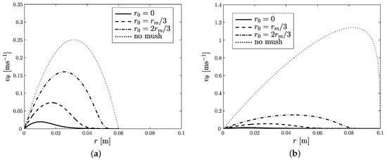
Figure 16.
Azimuthal velocity, , vs. radial distance, r, for and no mush, with: (a) m; and (b) m.
The model in [33] can be extended in a number of ways. First, although the casting velocity was not included in this analysis, it can be incorporated without affecting the analysis. After that, it would be of interest to include an equation for the conservation of heat, so that the temperature and hence the liquid fraction are computed as part of the model, rather than the liquid fraction simply being prescribed, as was the case in [33]. A nondimensional analysis would make it clear whether the effect of the magnetic field affects the heat transfer in the problem, through either Joule heating or convection. Once these models are in place, it should be possible to assess the role of stirring in macrosegregation and crystal structure formation: with respect to white-band formation in the case of the former [87,99,100], and columnar-to-equiaxed crystal transition in the case of the latter. A parallel line of activity would be to adapt these ideas to linear travelling magnetic fields for rectangular slabs, billets and blooms.
7. Conclusions
This paper has reviewed recent efforts in employing applied mathematical techniques, predominantly analysis and asymptotic methods, for the modelling of continuous casting processes. The focus has been on using these techniques in order not only to infer the qualitative behaviour of models, but also with a view to obtaining reduced-model formulations that require considerably less computational time than the original models, whilst still retaining their salient physical features. The work presented was divided into five topics: metallurgical length; air-gap formation and mould taper; oscillation-mark formation; macrosegregation; and electromagnetic stirring. Whilst work on all of these is still ongoing, a certain degree of validation has already been achieved:
- For the determination of metallurgical length, the proposed approach already yielded good agreement with a more computationally intensive approach using CFD and turbulence modelling [21], for the case of a pure metal, and with a more conventional enthalpy-formulation approach for alloys [22].
- For solidification shrinkage-induced macrosegregation in a binary alloy, reasonably good quantitative agreement was achieved for the cross-sectional macrosegregation profile, and even better agreement is to expected when the model has been developed to include superheat [23].
- For oscillation-mark formation, very good agreement was obtained with experimental results for fold-type marks [30].
For air-gap formation and mould taper, validation will soon be attempted against the results of Kelly et al. [47] for the continuous casting of round billets. For electromagnetic stirring, validation will be possible against the original experimental results of Dubke et al. [84], although this work is perhaps more embryonic, in view of an anomaly in the modelling of EMS in continuous casting that was recently found in [31].
In addition to the possible extensions of the work already carried out in each of these topics, which are detailed towards the end of Section 2, Section 3, Section 4, Section 5 and Section 6, these topics also form the starting points of investigations into a variety of as yet under-researched areas in continuous casting. Amongst these are the following:
Exudation For the case of alloys that have a long solidification interval—for example, alloys of copper or aluminium [41,66,70,101,102]—interdendritic melt seeps out through the air gap that forms between the solidifying shell and the chilled mould surface; this is known as exudation. Mathematically, this means that the region at in Figure 4 is effectively an outlet for the interdendritic melt. The situation is an example of macrosegregation that requires the methods developed in Section 2 and Section 5.
Columnar-equiaxed transition In the continuous casting of steel, it is well-established that the solidified structure consists of equiaxed crystals in the centre of the casting, surrounded by a columnar crystals, and that EMS is often to used to increase the extent of the equiaxed zone, by means, it is believed, of dendrite fragmentation. However, models which can predict the columnar-to-equiaxed transition (CET) and how it can be affected by EMS are non-existent, although there is some work on CET using the cellular automaton method [103,104,105].
V-segregation V-segregation is the name given to the eponymously-shaped channels that are formed in the centre of the equiaxed zone of continuously cast steel slabs, blooms and billets, in which the macrosegregation level of interstitial elements such as carbon and sulphur, and of substitutional elements such as molybdenum and chromium, can be quite extensive. Even today, the mechanism behind the development of V-shaped segregate channels or lines is still not well understood [106]. The appearance of the V-segregates differs between different cast sizes, width of the equiaxed zone and casting speed. V-segregates can be found in low alloyed steels, as well as in stainless and high-alloyed steels.
Centreline porosity Continuously cast products develop centreline porosity along the strand direction, as a result of an extended mushy zone in the centre of the solidifying material. The length of the mushy zone depends mainly on solidification mode, degree of solidification shrinkage, extent of the equiaxed zone, cross section dimensions and casting speed. In particular, the centre pore develops due to a lack of feeding to compensate for the solidification shrinkage. When the pressure in the centre decreases below the equilibrium pressure for gas phase, porosity will develop, with the pore growing along the centre line. Although internal porosity is well-studied for ingot and component casting [107,108,109], this is far from the case for continuous casting [110].
Mechanical soft reduction A method used to counteract V-segregations, centreline porosity and centreline segregation is mechanical soft reduction [111,112,113], whereby the cast steel cross section is reduced by pinch rollers to compensate for the downward liquid flow in the mushy zone due to solidification shrinkage.
Lastly, we point out the relevance of the above to the thermo-fluid dynamics topics that are relevant to as-cast quality, particularly in the continuous casting of steel. Although such topics are numerous, the work on oscillation-mark formation begins to address surface quality; moreover, it provides a relatively cheap computational framework for considering the formation and propagation of surface cracks, as are known to occur, for example, in peritectic steels [114]. Furthermore, although the work on macrosegregation considered only solidification shrinkage, it already contains the full array of momentum, heat and solute conservation equations that would be required to model macrosegregation due to other causes: for example, thermosolutal convection [115], or electromagnetic stirring, which is known to produce so-called white bands in the casting of steel [87,99,100,116,117], but which has never been properly modelled. Moreover, the work on solidification shrinkage-induced macrosegregation may help to inform on centreline porosity. Although the analysis in [23] did not dwell on the second term in the regular perturbation series for pressure, this quantity becomes negative and unbounded as full solidification is reached at the centreline, if the lever rule is used to describe segregation at the microscale; this would indicate that the pressure as a whole tends to zero, meaning the appearance of a pore. In addition, it is apparent that the pressure does not behave in this way for other microsegregation rules. It would be impossible to deduce this qualitative behaviour from numerical simulations alone, which further highlights the benefit of thinking asymptotically.
Funding
The author would like to thank FAPESP (Fundação de Amparo a Pesquisa do Estado de São Paulo) for the award of a visiting researcher grant [Grant Number 2018/07643-8].
Conflicts of Interest
The author declares no conflict of interest.
Appendix A. Notes on Practical Asymptotics
As indicated in Section 1, this article has been underpinned by the use of practical asymptotics; however, there has not been space to show details of how it works, and this issue is now addressed here.
To begin with, one would need to demonstrate the following four steps in action in the topics considered in Section 2, Section 3, Section 4, Section 5 and Section 6:
- (a)
- Nondimensionalization of the original governing equations;
- (b)
- Analysis of the nondimensionalized governing equations, and identification of the key dimensionless parameters and asymptotic reduction;
- (c)
- Evidence that the computation of the reduced model is cheaper than the computation of the original model would have been (if the reduced model does not have an analytical solution); and
- (d)
- Evidence of agreement between the results of the original model and the asymptotically reduced model.
Moreover, point (c) presupposes that one has indeed solved the problem in both the computationally intensive way and the cheap way; however, in practice, the visibility of “computational cheapness” comes from the observation that it ought to be cheaper to compute the numerical solutions for:
- Fewer partial differential equations (PDEs) rather than more;
- One-dimensional models rather than two-dimensional models, and two-dimensional models rather than three-dimensional models;
- Ordinary differential equations (ODEs) rather than PDEs; and
- Problems having fewer model parameters rather than more, with regard to the need for parameter studies to obtain a complete understanding of model behaviour.
Even so, there are examples in other areas of science and technology where a given problem has been solved both ways and the computational cost, in terms of CPU (central processing unit) time and RAM (random access memory), has been compared [118,119,120,121,122,123], although this was not done for the problems considered here.
In this context, we return to the problem of determining the metallurgical length in Section 2.1:
- The original model was two-dimensional steady-state, consisted of six PDEs and contained 32 model parameters [34,35].
- After nondimensionalization and asymptotic reduction, the model was one-dimensional and transient-like, consisted of two PDEs (or effectively different representations of the same PDE) and contained six model parameters [21].
- A direct comparison of CPU time and RAM was not carried out, but we note that one computation in [35] required 30 h of CPU time on a Cray J932 Supercomputer—with current computational architectures, this would no doubt take much less, but still would not be as short as the few seconds required for the formulation in [21].
- The agreement between the model results was very good, as shown in Figure 3.
Thus, this example demonstrates quite concretely how the asymptotic approach has been successfully applied.
References
- Return to Introduction to Continuous Casting. Available online: http://ccc.illinois.edu/introduction/overview.html#fig1 (accessed on 6 November 2018).
- Thomas, B.G. Review on modeling and simulation of continuous casting. Steel Res. Int. 2018, 89, 1700312. [Google Scholar] [CrossRef]
- Kuiken, H.K. Practical Asymptotics; Kluwer Academic Publishers: Dordrecht, The Netherlands, 2001. [Google Scholar]
- Holmes, M.H.; King, J.R. Practical Asymptotics II. J. Eng. Math. 2003, 45, 155–404. [Google Scholar] [CrossRef]
- Witelski, T.P.; Rienstra, S.W. Introduction to Practical Asymptotics III. J. Eng. Math. 2005, 53, 199. [Google Scholar] [CrossRef]
- McCue, S.W. Preface to the fourth special issue on practical asymptotics. J. Eng. Math. 2009, 63, 153–154. [Google Scholar] [CrossRef]
- Korobkin, A. Preface to the fifth special issue on practical asymptotics. J. Eng. Math. 2011, 69, 111–112. [Google Scholar] [CrossRef]
- Smith, W.R. Preface to the sixth special issue on “Practical Asymptotics”. J. Eng. Math. 2017, 102, 1–2. [Google Scholar] [CrossRef]
- Schilders, W.H.A.; van der Vorst, H.A.; Rommes, J. (Eds.) Model Order Reduction: Theory, Research Aspects and Applications, 1st ed.; Mathematics in Industry 13; Springer: Berlin/Heidelberg, Germany, 2008. [Google Scholar]
- Voller, V.R.; Porte-Agel, F. Moore’s law and numerical modeling. J. Comput. Phys. 2002, 179, 698–703. [Google Scholar] [CrossRef]
- Pickering, E.J.; Chesman, C.; Al-Bermani, S.; Holland, M.; Davies, P.; Talamantes-Silva, J. A comprehensive case study of macrosegregation in a steel ingot. Metall. Mater. Trans. B 2015, 46, 1860–1874. [Google Scholar] [CrossRef]
- DiLellio, J.A.; Young, G.W. An asymptotic model of the mold region in a continuous steel caster. Metall. Mater. Trans. B 1995, 26B, 1225–1241. [Google Scholar] [CrossRef]
- Smelser, R.E.; Johnson, R.E. An asymptotic model of slab casting. Int. J. Mech. Sci. 1995, 37, 793–814. [Google Scholar] [CrossRef]
- Johnson, R.E.; Cherukuri, H.P. Vertical continuous casting of bars. Proc. R. Soc. A 1999, 455, 227–244. [Google Scholar] [CrossRef]
- Cherukuri, H.P.; Johnson, R.E. Modelling vertical continuous casting with temperature-dependent material properties. Int. J. Mech. Sci. 2001, 43, 1243–1257. [Google Scholar] [CrossRef]
- Bland, D.R. Flux and the continuous casting of steel. IMA J. Appl. Maths 1984, 32, 89–112. [Google Scholar] [CrossRef]
- Hill, J.M.; Wu, Y.H. On a nonlinear Stefan problem in the continuous casting of steel. Acta Mech. 1994, 107, 183–198. [Google Scholar] [CrossRef]
- Hill, J.M.; Wu, Y.H.; Wiwatanapataphee, B. Analysis of flux flow and the formation of oscillation marks in the continuous caster. J. Eng. Math. 1999, 36, 311–326. [Google Scholar] [CrossRef]
- King, J.R.; Lacey, A.A.; Please, C.P.; Wilmott, P.; Zoryk, A. The formation of oscillation marks on continuously cast steel. Math. Eng. Ind. 1993, 4, 91–106. [Google Scholar]
- Howison, S.D. Practical Applied Mathematics: Modelling, Analysis, Approximation; Cambridge University Press: Cambridge, UK, 2005. [Google Scholar]
- Mitchell, S.L.; Vynnycky, M. Verified reduction of a model for a continuous casting process. Appl. Math. Mod. 2017, 48, 476–490. [Google Scholar] [CrossRef]
- Vynnycky, M.; Saleem, S. On the explicit resolution of the mushy zone in the modelling of the continuous casting of alloys. Appl. Math. Mod. 2017, 50, 544–568. [Google Scholar] [CrossRef]
- Vynnycky, M.; Saleem, S.; Fredriksson, H. An asymptotic approach to solidification shrinkage-induced macrosegregation in the continuous casting of binary alloys. Appl. Math. Mod. 2018, 54, 605–626. [Google Scholar] [CrossRef]
- Vynnycky, M. An asymptotic model for the formation and evolution of air gaps in vertical continuous casting. Proc. R. Soc. A 2009, 465, 1617–1644. [Google Scholar] [CrossRef]
- Vynnycky, M. Air gaps in vertical continuous casting in round moulds. J. Eng. Math. 2010, 68, 129–152. [Google Scholar] [CrossRef]
- Vynnycky, M. On the role of radiative heat transfer in air gaps in vertical continuous casting. Appl. Math. Mod. 2013, 37, 2178–2188. [Google Scholar] [CrossRef]
- Vynnycky, M. On the onset of air-gap formation in vertical continuous casting with superheat. Int. J. Mech. Sci. 2013, 73, 69–76. [Google Scholar] [CrossRef]
- Florio, B.J.; Vynnycky, M.; Mitchell, S.L.; O’Brien, S.B.G. Mould-taper asymptotics and air gap formation in continuous casting. Appl. Math. Comput. 2015, 268, 1122–1139. [Google Scholar] [CrossRef]
- Florio, B.J.; Vynnycky, M.; Mitchell, S.L.; O’Brien, S.B.G. On the interactive effects of mould taper and superheat on air gaps in continuous casting. Acta Mech. 2017, 228, 233–254. [Google Scholar] [CrossRef]
- Vynnycky, M.; Saleem, S.; Devine, K.M.; Florio, B.J.; Mitchell, S.L.; O’Brien, S.B.G. On the formation of fold-type oscillation marks in the continuous casting of steel. R. Soc. Open Sci. 2017, 4, 176002. [Google Scholar] [CrossRef] [PubMed]
- Vynnycky, M. On an anomaly in the modeling of electromagnetic stirring in continuous casting. Metall. Mater. Trans. B 2018, 49B, 399–410. [Google Scholar] [CrossRef]
- Vynnycky, M.; Zambrano, M. Towards a “moving-point” formulation for the modelling of oscillation-mark formation in the continuous casting of steel. Appl. Math. Mod. 2018, 63, 243–265. [Google Scholar] [CrossRef]
- Vynnycky, M. Porous-media braking of electromagnetic stirring in the continuous casting of steel. In Proceedings of the 24th ABCM International Congress of Mechanical Engineering, Curitiba, Brazil, 3–8 December 2017. [Google Scholar]
- Mahmoudi, J.; Vynnycky, M.; Fredriksson, H. Modelling of fluid flow, heat transfer and solidification in the strip casting of a copper base alloy: (III). Solidification—A theoretical study. Scand. J. Metall. 2001, 30, 136–145. [Google Scholar] [CrossRef]
- Mahmoudi, J.; Vynnycky, M.; Sivesson, P.; Fredriksson, H. An experimental and numerical study on the modelling of fluid flow, heat transfer and solidification in a copper continuous strip casting process. Mater. Trans. 2003, 44, 1741–1751. [Google Scholar] [CrossRef]
- AEA Technology. CFX 4.2 Flow Solver User Guide; AEA Technology: Harwell, UK, 1995. [Google Scholar]
- Swaminathan, C.R.; Voller, V.R. A general enthalpy method for modeling solidification processes. Met. Trans. B 1992, 23B, 651–664. [Google Scholar] [CrossRef]
- Voller, V.R.; Peng, S. An enthalpy formulation based on an arbitrarily deforming mesh for solution of the Stefan problem. Comput. Mech. 1994, 14, 492–502. [Google Scholar] [CrossRef]
- Aboutalebi, M.R.; Hasan, M.; Guthrie, R.I.L. Numerical study of coupled turbulent flow and solidification for steel slab casters. Numer. Heat Transf. 1995, 28, 279–297. [Google Scholar] [CrossRef]
- Aboutalebi, M.R.; Hasan, M.; Guthrie, R.I.L. Coupled turbulent flow, heat and solute transport in continuous casting processes. Metall. Mater. Trans. B 1995, 26, 731–744. [Google Scholar] [CrossRef]
- Thevik, H.J.; Mo, A.; Rusten, T. A mathematical model for surface segregation in aluminum direct chill casting. Metall. Mater. Trans. B 1999, 39, 135–142. [Google Scholar] [CrossRef]
- Savage, J. A theory of heat transfer and air gap formation in continuous casting molds. J. Iron Steel Inst. 1962, 198, 41–47. [Google Scholar]
- Richmond, O.; Tien, R.H. Theory of thermal stresses and air-gap formation during the early stages of solidification in a rectangular mold. J. Mech. Phys. Solids 1971, 19, 273–284. [Google Scholar] [CrossRef]
- Kristiansson, J.O. Thermal stresses in the early stage of the solidification of steel. J. Therm. Stresses 1982, 5, 315–330. [Google Scholar] [CrossRef]
- Tien, R.H.; Richmond, O. Theory of maximum tensile stresses in the solidifying shell of a constrained regular casting. J. Appl. Mech. 1982, 49, 481–486. [Google Scholar] [CrossRef]
- Kim, K.Y. Analysis of gap formation at mold-shell interface during solidification of aluminium alloy plate. ISIJ Int. 2003, 43, 647–652. [Google Scholar] [CrossRef]
- Kelly, J.E.; Michalek, K.P.; O’Connor, T.G.; Thomas, B.G.; Dantzig, J.A. Initial development of thermal and stress fields in continuously cast steel billets. Metall. Mater. Trans. A 1988, 19A, 2589–2602. [Google Scholar] [CrossRef]
- Grill, A.; Sorimachi, K.; Brimacombe, J.K. Heat flow, gap formation and break-outs in the continuous casting of steel slabs. Metall. Mater. Trans. B 1976, 7B, 177–189. [Google Scholar] [CrossRef]
- Bellet, M.; Decultieux, F.; Menai, M.; Bay, F.; Levaillant, C.; Chenot, J.L.; Schmidt, P.; Svensson, I.L. Thermomechanics of the cooling stage in casting processes: Three-dimensional finite element analysis and experimental validation. Metall. Mater. Trans. B 1996, 27, 81–99. [Google Scholar] [CrossRef]
- Huespe, A.E.; Cardona, A.; Fachinotti, V. Thermomechanical model of a continuous casting process. Comput. Methods Appl. Mech. Eng. 2000, 182, 439–455. [Google Scholar] [CrossRef]
- Li, C.; Thomas, B.G. Thermomechanical finite-element model of shell behavior in continuous casting of steel. Metall. Mater. Trans. B 2004, 35B, 1151–1172. [Google Scholar] [CrossRef]
- Sun, D.; Annapragada, S.R.; Garimella, S.V.; Singh, S.K. Analysis of gap formation in the casting of energetic materials. Numer. Heat Transf. 2007, 51, 415–444. [Google Scholar] [CrossRef]
- Saleem, S. On the Surface Quality of Continuously Cast Steels and Phosphor Bronzes. Ph.D. Thesis, KTH Royal Institute of Technology, Stockholm, Sweden, 2016. [Google Scholar]
- Saleem, S.; Vynnycky, M.; Fredriksson, H. A study of the oscillation marks’ characteristics of continuously cast Incoloy alloy 825 blooms. Metall. Mater. Trans. A 2016, 47, 4068–4079. [Google Scholar] [CrossRef]
- Takeuchi, E.; Brimacombe, J.K. The formation of oscillation marks in the continuous casting of steel slabs. Metall. Mater. Trans. B 1984, 15, 493–509. [Google Scholar] [CrossRef]
- Jonayat, A.S.M.; Thomas, B.G. Transient thermo-fluid model of meniscus behavior and slag consumption in steel continuous casting. Metall. Mater. Trans. A 2014, 45, 1842–1864. [Google Scholar] [CrossRef]
- Tomono, H. Elements of Oscillation Mark Formation and Their Effect on Transverse Fine Cracks in Continuous Casting of Steel. Ph.D. Thesis, École Polytechnique Fédérale de Lausanne, Lausanne, Switzerland, 1979. [Google Scholar]
- Ramirez-Lopez, P.E.; Lee, P.D.; Mills, K.C. Explicit modelling of slag infiltration and shell formation during mould oscillation in continuous casting. ISIJ Int. 2010, 50, 425–434. [Google Scholar] [CrossRef]
- Ramirez-Lopez, P.E.; Lee, P.D.; Mills, K.C.; Santillana, B. A new approach for modelling slag infiltration and solidification in a continuous casting mould. ISIJ Int. 2010, 50, 1797–1804. [Google Scholar] [CrossRef]
- Lee, P.D.; Ramirez-Lopez, P.E.; Mills, K.C.; Santillana, B. Review: The “butterfly effect” in continuous casting. Ironmak. Steelmak. 2012, 39, 244–253. [Google Scholar] [CrossRef]
- Ramirez-Lopez, P.E.; Mills, K.C.; Lee, P.D.; Santillana, B. A unified mechanism for the formation of oscillation marks. Metall. Mater. Trans. B 2012, 43B, 109–122. [Google Scholar] [CrossRef]
- Bikerman, J.J. Physical Surfaces; Academic Press: New York, NY, USA, 1970. [Google Scholar]
- Flemings, M.C.; Nereo, G.E. Macrosegregation. I. AIME Met. Soc. Trans. 1967, 239, 1449–1461. [Google Scholar]
- Flemings, M.C.; Mehrabian, R.; Nereo, G.E. Macrosegregation. PT. 2. AIME Met. Soc. Trans. 1968, 242, 41–49. [Google Scholar]
- Reddy, A.V.; Beckermann, C. Modeling of macrosegregation due to thermosolutal convection and contraction-driven flow in direct chill continuous casting of an Al-Cu round ingot. Metall. Mater. Trans. B 1997, 28, 479–489. [Google Scholar] [CrossRef]
- Saleem, S.; Vynnycky, M.; Fredriksson, H. Formation of the tin rich layer and inverse segregation in phosphor bronzes during continuous casting. In Proceedings of the Minerals, Metals and Materials Society (TMS) 2015: 144th Annual Meeting and Exhibition, Orlando, FL, USA, 15–19 March 2015; pp. 15–22. [Google Scholar]
- Diao, Q.Z.; Tsai, H.L. Modelling of solute redistribution in the mushy zone during solidification of aluminium-copper alloys. Metall. Trans. 1993, 24A, 963–973. [Google Scholar] [CrossRef]
- Chen, J.H.; Tsai, H.L. Inverse segregation for a unidirectional solidification of aluminium-copper alloys. Int. J. Heat Mass Transf. 1993, 36, 3069–3075. [Google Scholar] [CrossRef]
- Diao, Q.Z.; Tsai, H.L. The formation of negative- and positive-segregated bands during solidification of aluminum-copper alloys. Int. J. Heat Mass Transf. 1993, 36, 4299–4305. [Google Scholar] [CrossRef]
- Mo, A. Mathematical modelling of surface segregation in aluminum DC casting caused by exudation. Int. J. Heat Mass Transf. 1993, 36, 4335–4340. [Google Scholar] [CrossRef]
- Voller, V.R.; Sundarraj, S. A model of inverse segregation: The role of microporosity. Int. J. Heat Mass Transf. 1995, 38, 1009–1018. [Google Scholar] [CrossRef]
- Minakawa, S.; Samarasekera, I.V.; Weinberg, F. Inverse segregation. Metall. Trans. 1985, 16, 595–604. [Google Scholar] [CrossRef]
- Du, Q.; Eskin, D.G.; Katgerman, L. Numerical issues in modelling macrosegregation during DC casting of a multi-component aluminium alloy. Int. J. Numer. Methods Heat Fluid Flow 2009, 19, 917–930. [Google Scholar] [CrossRef]
- Jalanti, T.; Swierkosz, M.; Gremaud, M.; Rappaz, M. Modelling of macrosegregation in continuous casting of aluminium. In Continuous Casting; Ehrke, K., Schneider, W., Eds.; WILEY-VCH Verlag GmbH: Weinheim, Germany, 2006; pp. 191–198. [Google Scholar]
- Založnik, M.; Xin, S.; Šarler, B. Verification of a numerical model of macrosegregation in direct chill casting. Int. J. Numer. Methods Heat Fluid Flow 2008, 18, 308–324. [Google Scholar] [CrossRef]
- Venneker, B.C.H.; Katgerman, L. Modelling issues in macrosegregation predictions in direct chill castings. J. Light Met. 2002, 2, 149–159. [Google Scholar] [CrossRef]
- Eskin, D.G.; Zuidema, J.; Savran, V.I.; Katgerman, L. Structure formation and macrosegregation under different process conditions during DC casting. Mater. Sci. Eng. A 2004, 384, 232–244. [Google Scholar] [CrossRef]
- Eskin, D.G.; Du, Q.; Katgerman, L. Relationship between shrinkage-induced macrosegregation and the sump profile upon direct-chill casting. Scr. Mater. 2006, 55, 715–718. [Google Scholar] [CrossRef]
- Du, Q.; Eskin, D.G.; Katgerman, L. Modeling macrosegregation during direct-chill casting of multicomponent aluminum alloys. Metall. Mater. Trans. A 2007, 38A, 180–189. [Google Scholar] [CrossRef]
- Jalanti, T. Etude et Modélisation de la Macroségrégation dans la Coulée Semi-Continue des Alliages d’Aluminium. Ph.D. Thesis, École Polytechnique Fédérale de Lausanne, Lausanne, Switzerland, 2000. [Google Scholar]
- Fredriksson, H.; Åkerlind, U. Materials Processing during Casting; Wiley: Chichester, UK, 2006. [Google Scholar]
- Tzavaras, A.A.; Brody, H.D. Electromagnetic stirring and continuous-casting—Achievements, problems, and goals. J. Met. 1984, 36, 31–37. [Google Scholar] [CrossRef]
- Spitzer, K.H.; Dubke, M.; Schwerdtfeger, K. Rotational electromagnetic stirring in continuous-casting of round strands. Metall. Mater. Trans. B 1986, 17, 119–131. [Google Scholar] [CrossRef]
- Dubke, M.; Tacke, K.H.; Spitzer, K.H.; Schwerdtfeger, K. Flow fields in electromagnetic stirring of rectangular strands with linear inductors: Part I. Theory and experiments with cold models. Metall. Mater. Trans. B 1988, 19B, 581–593. [Google Scholar] [CrossRef]
- Dubke, M.; Tacke, K.H.; Spitzer, K.H.; Schwerdtfeger, K. Flow fields in electromagnetic stirring of rectangular strands with linear inductors: Part II. Computation of flow fields in billets, blooms, and slabs of steel. Metall. Mater. Trans. B 1988, 19, 595–602. [Google Scholar] [CrossRef]
- Dubke, M.; Spitzer, K.H.; Schwerdtfeger, K. Spatial-distribution of magnetic-field of linear inductors used for electromagnetic stirring in continuous-casting of steel. Ironmak. Steelmak. 1991, 18, 347–353. [Google Scholar]
- Tacke, K.H.; Grill, A.; Miyazawa, K.; Schwerdtfeger, K. Macrosegregation in strand cast steel—Computation of concentration profiles with a diffusion-model. Arch. Eisenhüttenw. 1981, 52, 15–20. [Google Scholar] [CrossRef]
- Tacke, K.H.; Schwerdtfeger, K. Stirring velocities in continuously cast round billets as induced with rotating electromagnetic-fields. Stahl und Eisen 1979, 99, 7–12. [Google Scholar]
- Zhang, C.; Shatrov, V.; Priede, J.; Eckert, S.; Gerbeth, G. Intermittent behavior caused by surface oxidation in a liquid metal flow driven by a rotating magnetic field. Metall. Mater. Trans. B 2011, 42, 1188–1200. [Google Scholar] [CrossRef]
- Liu, H.; Xu, M.; Qiu, S.; Zhang, H. Numerical simulation of fluid flow in a round bloom mold with in-mold rotary electromagnetic stirring. Metall. Mater. Trans. B 2012, 43, 1657–1675. [Google Scholar] [CrossRef]
- Yang, J.; Xie, Z.; Ning, J.; Liu, W.; Ji, Z. A framework for soft sensing of liquid pool length of continuous casting round blooms. Metall. Mater. Trans. B 2014, 45, 1545–1556. [Google Scholar] [CrossRef]
- Poole, G.M.; Heyen, M.; Nastac, L.; El-Kaddah, N. Numerical modeling of macrosegregation in binary alloys solidifying in the presence of electromagnetic stirring. Metall. Mater. Trans. B 2014, 45, 1834–1841. [Google Scholar] [CrossRef]
- Ren, B.Z.; Chen, D.F.; Wang, H.D.; Long, M.J.; Han, Z.W. Numerical simulation of fluid flow and solidification in bloom continuous casting mould with electromagnetic stirring. Ironmak. Steelmak. 2015, 42, 401–408. [Google Scholar] [CrossRef]
- Fang, Q.; Ni, H.; Zhang, H.; Wang, B.; Lv, Z. The effects of a submerged entry nozzle on flow and initial solidification in a continuous casting bloom mold with electromagnetic stirring. Metals 2017, 7, 146. [Google Scholar] [CrossRef]
- Wang, X.; Fautrelle, Y.; Etay, J.; Moreau, R. A periodically reversed flow driven by a modulated traveling magnetic field: Part I. Experiments with GaInSn. Metall. Mater. Trans. B 2009, 40, 82–90. [Google Scholar] [CrossRef]
- Eckert, S.; Nikrityuk, P.A.; Raebiger, D.; Eckert, K.; Gerbeth, G. Efficient melt stirring using pulse sequences of a rotating magnetic field: Part I. Flow field in a liquid metal column. Metall. Mater. Trans. B 2007, 38, 977–988. [Google Scholar] [CrossRef]
- Beitelman, L.S.; Curran, C.P.; Lavers, J.D.; Tallback, G. Modulated Electromagnetic Stirring of Metals at Advanced Stage of Solidification. EP Patent EP080783247, 22 August 2011. [Google Scholar]
- Versteeg, H.; Malalasekera, W. An Introduction to Computational Fluid Dynamics: The Finite Volume Method, 2nd ed.; Pearson: Harlow, UK, 2007. [Google Scholar]
- Bridge, M.R.; Rogers, G.D. Structural effects and band segregate formation during the electromagnetic stirring of strand-cast steel. Met. Trans. B 1984, 15, 581–589. [Google Scholar] [CrossRef]
- Kor, G.J.W. Influence of circumferential electromagnetic stirring on macrosegregation in steel. Ironmak. Steelmak. 1982, 9, 244–251. [Google Scholar]
- M’Hamdi, M.; Håkonsen, A. Experimental and numerical study of surface macrosegregation in DC casting of aluminium sheet ingots. In Modeling of Casting, Welding and Advanced Solidification Processes-X, Proceedings of the 10th International Conference on Modeling of Casting, Welding and Advanced Solidification Processes, Destin, FL, USA, 25–30 May 2003; Stefanescu, D.M., Warren, J.A., Jolly, M.R., Krane, M.J.M., Eds.; Minerals, Metals & Materials Soc.: Warrendale, PA, USA, 2003; pp. 505–512. [Google Scholar]
- Haug, E.; Mo, A.; Thevik, H.J. Macrosegregation near a cast surface caused by exudation and solidification shrinkage. Int. J. Heat Mass Transf. 1995, 38, 1553–1563. [Google Scholar] [CrossRef]
- Luo, Y.Z.; Zhang, J.M.; Wei, X.D.; Xiao, C.; Hu, Z.F.; Yuan, Y.Y.; Chen, S.D. Numerical simulation of solidification structure of high carbon SWRH77B billet based on the CAFE method. Ironmak. Steelmak. 2012, 39, 26–30. [Google Scholar] [CrossRef]
- Luo, S.; Zhu, M.; Louhenkilpi, S. Numerical simulation of solidification structure of high carbon steel in continuous casting using cellular automaton method. ISIJ Int. 2012, 52, 823–830. [Google Scholar] [CrossRef]
- Wang, W.; Ji, C.; Luo, S.; Zhu, M. Modeling of dendritic evolution of continuously cast steel billet with cellular automaton. Metall. Mater. Trans. B 2018, 49, 200–212. [Google Scholar] [CrossRef]
- Guan, R.; Ji, C.; Zhu, M.; Deng, S. Numerical simulation of V-shaped segregation in continuous casting blooms based on a microsegregation model. Metall. Mater. Trans. B 2018, 49, 2571–2583. [Google Scholar] [CrossRef]
- Lee, P.; Chirazi, A.; See, D. Modeling microporosity in aluminum-silicon alloys: A review. J. Light Met. 2001, 1, 15–30. [Google Scholar] [CrossRef]
- Dantzig, J.A.; Rappaz, M. Solidification; EPFL Press: Lausanne, Switzerland, 2009. [Google Scholar]
- Stefanescu, D.M. Computer simulation of shrinkage related defects in metal castings—A review. Int. J. Cast Met. Res. 2005, 18, 129–143. [Google Scholar] [CrossRef]
- Du, P. Numerical Modeling of Porosity and Macrosegregation in Continuous Casting of Steel. Ph.D. Thesis, University of Iowa, Iowa City, IA, USA, 2013. [Google Scholar]
- Rogberg, B.; Ek, L. Influence of soft reduction on the fluid flow, porosity and center segregation in CC high carbon- and stainless steel blooms. ISIJ Int. 2018, 58, 478–487. [Google Scholar] [CrossRef]
- Domitner, J.; Wu, M.; Kharicha, A.; Ludwig, A.; Kaufmann, B.; Reiter, J.; Schaden, T. Modeling the effects of strand surface bulging and mechanical softreduction on the macrosegregation formation in steel continuous casting. Metall. Mater. Trans. A 2014, 45, 1415–1434. [Google Scholar] [CrossRef]
- Mayer, F.; Wu, M.; Ludwig, A. On the formation of centreline segregation in continuous slab casting of steel due to bulging and/or feeding. Steel Res. Int. 2010, 81, 660–667. [Google Scholar] [CrossRef]
- Saleem, S.; Vynnycky, M.; Fredriksson, H. The influence of peritectic reaction/transformation on crack susceptibility in the continuous casting of steels. Metall. Mater. Trans. B 2017, 48, 1625–1635. [Google Scholar] [CrossRef]
- Sun, H.; Zhang, J. Study on the macrosegregation behavior for the bloom continuous casting: Model development and validation. Metall. Mater. Trans. B 2014, 45B, 1133–1149. [Google Scholar] [CrossRef]
- Hurtuk, D.J.; Tzavaras, A.A. Some effects of electromagnetically induced fluid-flow on macrosegregation in continuously cast steel. Metall. Trans. B Proc. Met. 1977, 8, 243–251. [Google Scholar] [CrossRef]
- Sasaki, K.; Sugitani, Y.; Kobayashi, S.; Ishimura, S. The effect of fluid flow on the formation of the negative segregation zone in steel ingots. Tetsu Hagane 1979, 65, 60–69. [Google Scholar] [CrossRef]
- Vynnycky, M.; Shugai, G.; Yakubenko, P.; Mellgren, N. Asymptotic reduction for numerical modeling of polymer electrolyte fuel cells. SIAM J. Appl. Math. 2009, 70, 455–487. [Google Scholar] [CrossRef]
- Ly, H.; Birgersson, E.; Vynnycky, M.; Sasmito, A.P. Validated reduction and accelerated numerical computation of a model for the proton exchange membrane fuel cell. J. Electrochem. Soc. 2009, 156, B1156–B1168. [Google Scholar] [CrossRef]
- Ly, H.; Birgersson, E.; Vynnycky, M. Asymptotically reduced model for a proton exchange membrane fuel cell stack: Automated model generation and verification. J. Electrochem. Soc. 2010, 157, B982–B992. [Google Scholar] [CrossRef]
- Ly, H.; Birgersson, E.; Vynnycky, M. Computationally efficient multi-phase models for a proton exchange membrane fuel cell: Asymptotic reduction and thermal decoupling. Int. J. Hydrog. Energy 2011, 36, 14573–14589. [Google Scholar] [CrossRef]
- Vynnycky, M.; Sharma, A.K.; Birgersson, E. A finite-element method for the weakly compressible parabolized steady 3D Navier-Stokes equations in a channel with a permeable wall. Comput. Fluids 2013, 81, 152–161. [Google Scholar] [CrossRef]
- Sharma, A.K.; Birgersson, E.; Vynnycky, M. Towards computationally-efficient modeling of transport phenomena in three-dimensional monolithic channels. Appl. Math. Comput. 2015, 254, 392–407. [Google Scholar] [CrossRef]
© 2018 by the author. Licensee MDPI, Basel, Switzerland. This article is an open access article distributed under the terms and conditions of the Creative Commons Attribution (CC BY) license (http://creativecommons.org/licenses/by/4.0/).