Article

Numerical Simulation of Electromagnetic Field in Round Bloom Continuous Casting with Final Electromagnetic Stirring

1
School of Metallurgical and Materials Engineering, Chongqing University of Science & Technology, Chongqing 401331, China
2
College of Materials Science and Engineering, Chongqing University, Chongqing 400044, China
3
Department of Continuous Casting, CISDI Engineering Co. Ltd., Chongqing 400013, China
*
Authors to whom correspondence should be addressed.
Metals 2018, 8(11), 903; https://doi.org/10.3390/met8110903
Submission received: 25 September 2018 / Revised: 1 November 2018 / Accepted: 1 November 2018 / Published: 5 November 2018
(This article belongs to the Special Issue Continuous Casting)

Abstract

:
A 3D mathematical model was developed to simulate the electromagnetic field in Φ600 mm round bloom continuous casting with final electromagnetic stirring (F-EMS), and the model was verified using measured data for the magnetic flux density in the stirrer centre. The distribution of electromagnetic force and the influence of current intensity and frequency were investigated. The results show that the Joule heat generated by F-EMS is very small and its influence on secondary cooling heat transfer in the stirring zone can be ignored. With an increase in current frequency, the electromagnetic force density at R/2 and R/3 of the Φ600 mm round bloom first increases and then decreases, reaching a maximum at 10 Hz.

1. Introduction

Continuous casting is a process generally used in steel production to make the molten steel solidified into a semi-finished billet, bloom, or slab for subsequent rolling in the finishing mills. Electromagnetic stirring (EMS) technology is widely used in the continuous casting production of steel. This technology utilises electromagnetic induction to provide a non-contact electromagnetic force to enhance the molten steel flow, heat transfer, and mass transfer and to promote columnar to equiaxed transition, thereby rectifying internal defects such as central segregation and shrinkage cavities [1]. According to different installation positions, three types of EMS exist in continuous casting steel. One is situated at the caster mould, referred to as mould electromagnetic stirring (M-EMS); another is situated along the strand in the secondary cooling zone, called a strand electromagnetic stirring (S-EMS); the last one is situated near the solidification end of the strand, known as final electromagnetic stirring (F-EMS) [2]. M-EMS is used in almost all billet/bloom casters. However, for high-carbon steel or large-section strands, the use of M-EMS cannot completely improve the internal quality of the strand, and F-EMS is generally required [3], which can more effectively improve the central porosity and V-shaped segregation of the strand [4,5]. Therefore, detailed analysis of the electromagnetic field, fluid flow, and solidification behaviour of the strand is very important for evaluating the impact of F-EMS on various metallurgical operations in the continuous casting process, and the electromagnetic field is the primary problem.
In 1986, Spitzer et al. deduced the analytical formula for the 2D electromagnetic force in an infinitely long stirring system [6]. Recently, Vynnycky [7] derived another form of analytical solution for the same issue with Ref. [6] when the tangential magnetic flux density was employed as the boundary condition. Trindade et al. [8], Yu et al. [9], and Liu et al. [10] studied the electromagnetic field of M-EMS, highlighting the obvious shielding effect of mould copper on the electromagnetic field, while that of F-EMS is different. Jiang et al. [11] and Sun et al. [3] focused mainly on fluid flow, solidification, and mass transfer of the continuous casting strand with F-EMS and rarely discussed the electromagnetic field. Therefore, this study aims to investigate the electromagnetic field in Φ600 mm round bloom continuous casting with F-EMS by numerical simulation, as well as examining the distribution features of the electromagnetic force and the influence of current intensity and frequency.

2. Mathematical Model

The continuous caster studied in this paper is produced by a domestic steel mill (Sunan Heavy Industry, Suzhou, China). Figure 1 is a structural diagram of the continuously cast round bloom with F-EMS. The origin of the coordinate is at the centre of the stirrer. The round bloom has a diameter of 600 mm and the stirrer core has a height of 300 mm.

2.1. Basic Assumption

The fluid flow in a continuous casting round bloom with F-EMS can be described by Maxwell’s equations and the Navier–Stokes equations, which are coupled by the electromagnetic force density and the flow velocity of the molten steel. In view of the complexity of the F-EMS process, several assumptions must be made in order to simplify the calculations.
  • In the F-EMS process, the magnetic Reynolds number (about 0.1) is far less than the shielding parameter (about 10) [10,12] and the angular frequency of the current intensity is much larger than the angular velocity of the molten steel; thus, the influence of the molten steel flow on the electromagnetic field is negligible [13]. Therefore, this problem can be decomposed into an electromagnetic problem and a fluid flow problem to be solved separately. In the present paper, only the electromagnetic field was calculated without regard to the flow field and solidification.
  • Since the current frequency of F-EMS is generally in the range of 4 Hz to 10 Hz, which belongs to the magnetic quasi-static field, the displacement current is ignored [8].
  • Both the outer shell and the cooling water jacket of the stirrer are approximated as an air zone for the benefit of the calculations.
  • The curve of the strand is negligible.

2.2. Control Equations

At low current frequencies, the time-varying electromagnetic field is assumed to be a magnetic quasi-static field, and Maxwell’s equations can be simplified as follows [8]:
· B = 0
× B = μ r μ 0 J
× E = B t
J = σ E
where B is the magnetic flux density, J is the induced current density in the strand, μ0 is the vacuum permeability, μr is the relative permeability, E is the electric field intensity, σ is the electrical conductivity, and t is the time.
The electromagnetic force density at each element is calculated by harmonic analysis using Equation (5) [8]:
F time = J × B
The expression for the Joule heat power density generated by the induced current is calculated from Equation (6) [14]:
P time = | J | 2 / σ
The time in Equations (5) and (6) refers to the real and imaginary parts of the variable at 0° and 90°, respectively.
Since F-EMS uses a sinusoidal current to generate a harmonic electromagnetic field, the magnetic flux density, electromagnetic force density and Joule heat power density change with time. However, at low current frequencies, both the shielding parameter and the interaction parameter are small, and it is feasible to use the time-averaged electromagnetic force density and Joule heat power density [15]. Hence, the time-averaged values of the two variables are calculated from Equations (7) and (8) in the post-processing to investigate the distribution characteristics [8]:
F em = ( F 0 + F 90 ) / 2
P ave = ( P 0 + P 90 ) / 2
Because the time-averaged value of the magnetic flux density is 0, the time-averaged value of its modulus is transiently calculated by using Equation (9):
B mag = f t 0 t 0 + 1 / f | B | d t
where f is the current frequency.

2.3. Boundary Conditions

An air cylinder with a radius of 0.9 m and a height of 2.2 m was established around the whole stirring system to calculate the electromagnetic field. The tangential magnetic condition (∂Φ/∂n) = 0 was applied at the outer surface of the air cylinder, where Φ is the reduced scalar potential and n is the normal unit vector to the surface [8,10]. The three-phase coil excitation was applied with source current intensity (I) and frequency.

2.4. Physical Properties

Before the Φ600 mm round bloom is completely solidified, its temperature is above 1173 K [16], which is greater than the Curie point of the steel (about 1023 K) [17]. Therefore, the strand is a paramagnetic material. In the calculation, it is considered that both the strand and the iron core of the stirrer are isotropic materials and that their relative permeability is constant. The relevant physical properties are as follows: the vacuum permeability is 1.257 × 10⁻⁶ H·m−1, the relative permeability of the strand and air is 1.0, the relative permeability of the iron core is 1000, and the electrical conductivity of the strand is 7.14 × 10⁵ S·m−1.

2.5. Solution

When calculating the electromagnetic field, the length of the strand is 1.8 m. ANSYS Emag software (ANSYS 14.0, ANSYS Inc., Canonsburg, PA, USA) was used to solve Maxwell’s equations by the finite element method (FEM). We employed three different meshes to verify the independence of the grid, which included 220,000, 270,000, and 350,000 elements, respectively. The comparison between simulation results and experimental data indicated that the errors of the three meshes are 7.2%, 4.6%, and 4.0%, respectively. Hence, a mesh of 270,000 elements was selected to obtain the mesh-independent results. The distribution of the electromagnetic field in the strand was obtained and the time-averaged electromagnetic force density was extracted. Except for the transient analysis of Bmag, other variables were calculated using harmonic analysis.

3. Results and Discussion

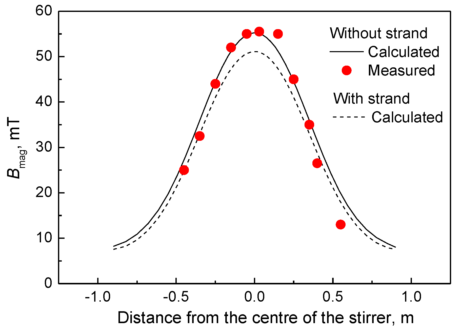
In order to validate the mathematical model of the electromagnetic field, the magnetic flux density in the stirrer was measured along the axial direction without the strand and compared with the numerical simulation results, as shown in Figure 2. The measurement of the magnetic flux density was carried out in a Φ600 mm round bloom continuous caster at a domestic steel mill by using a portable Gauss meter (Bell, FW5180). The calculated values agree well with the measured data, which supports the correctness of the mathematical model and the solution method for the electromagnetic field. Figure 2 also demonstrates that the magnetic flux density in the stirrer with the strand is significantly lower than that without the strand, and the maximum value decreases from 55.4 mT calculated without the strand to 51.1 mT with the strand. This is mainly due to the ‘skin effect’: the strand can shield the electromagnetic field, resulting in a decrease in magnetic flux density.
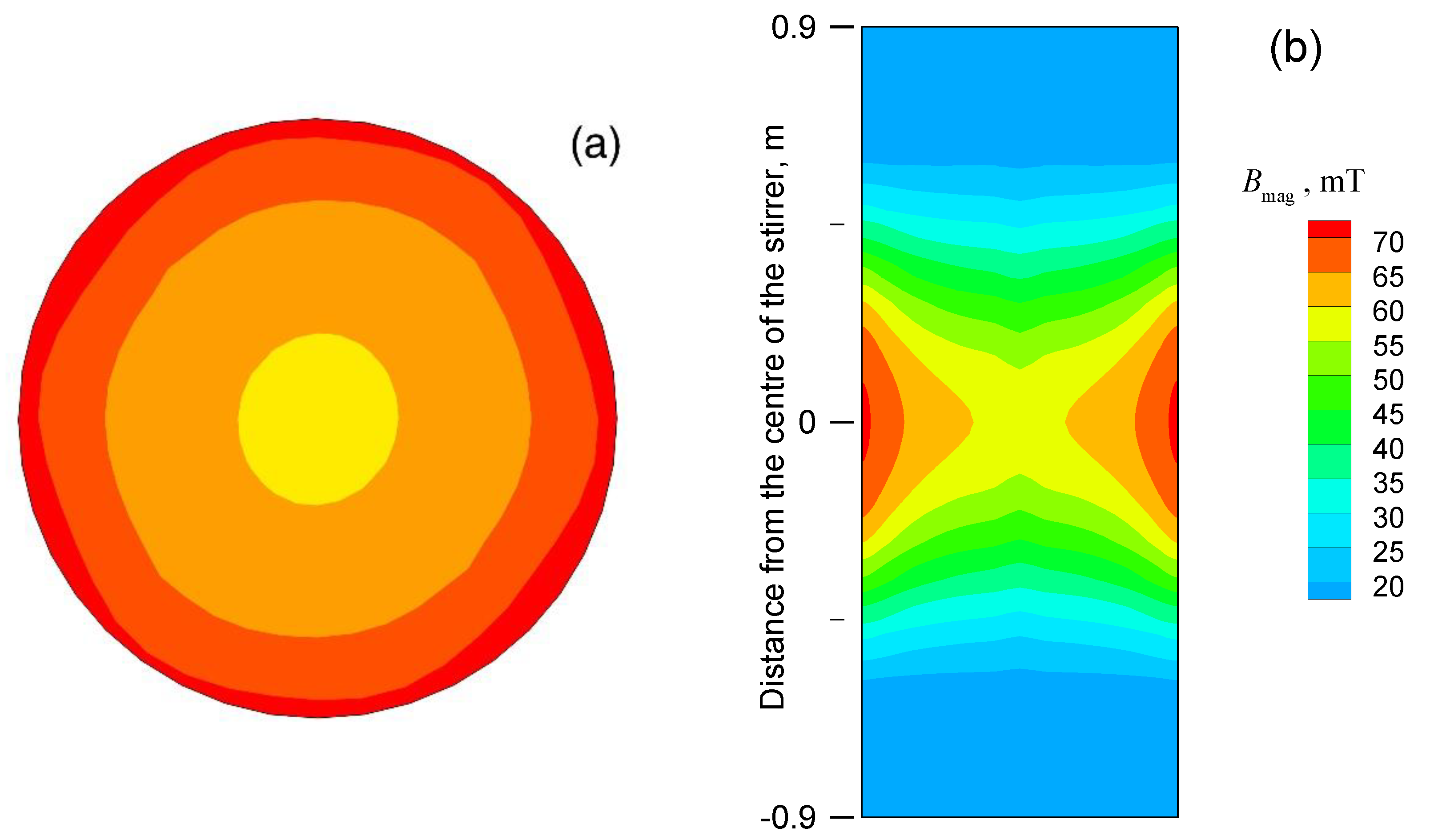
Figure 3 shows the distribution of the magnetic flux density in both the cross-section and the longitudinal section of the Φ600 mm round bloom at 400 A and 4 Hz. The magnetic flux density in the cross-section is roughly circularly symmetrical, and it is greatest at the edge and gradually attenuates towards the centre, as shown in Figure 3a. In the longitudinal section, the maximum value of the magnetic flux density appears in the middle of the stirrer and gradually weakens towards both ends, as shown in Figure 3b.
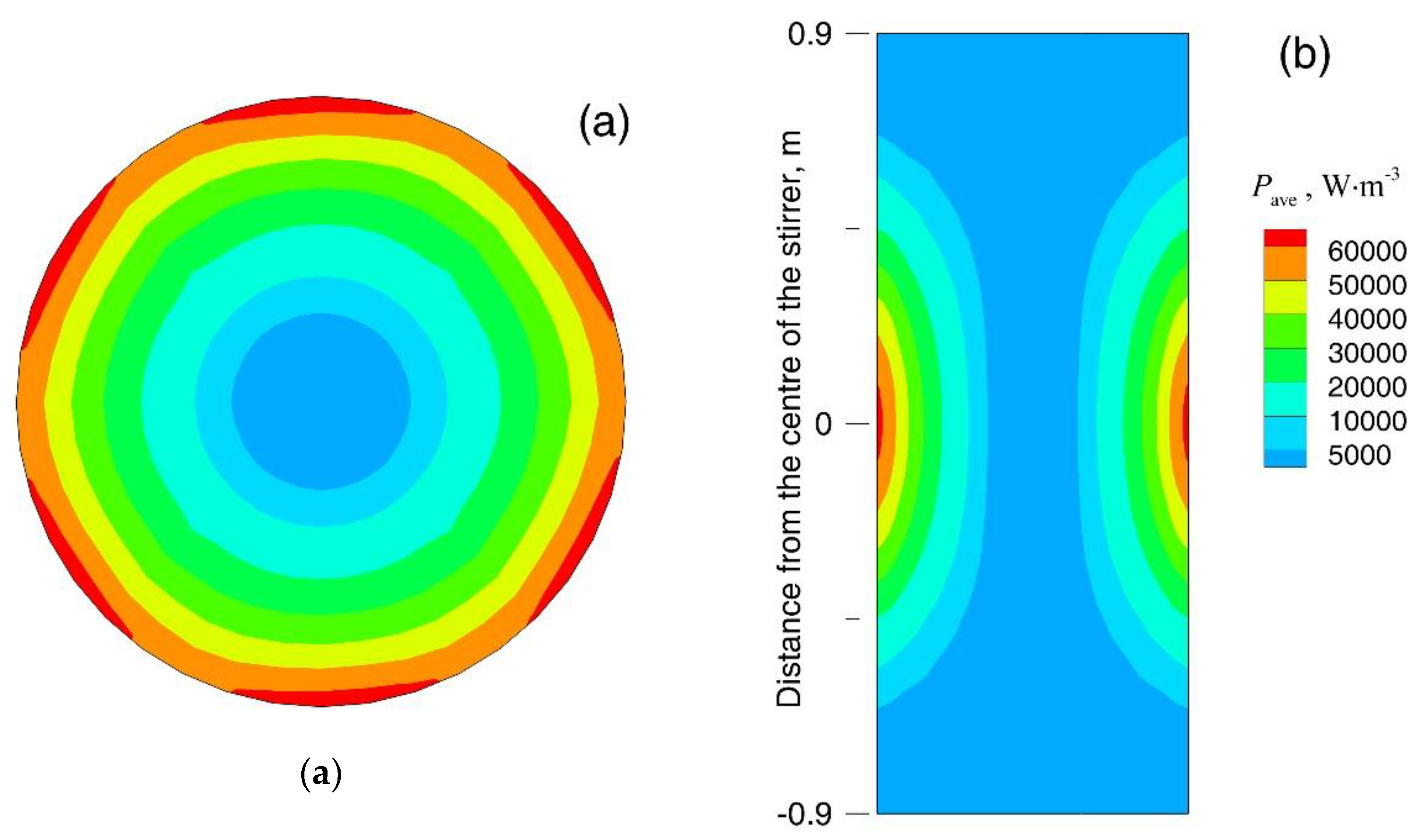
Figure 4 displays the distribution of the time-averaged Joule heat power density in both the cross-section and the longitudinal section of the Φ600 mm round bloom at 400 A and 4 Hz. The characteristic of the Joule heat power density distribution is very similar to that of the magnetic flux density. It can also be seen from Figure 4a that the distribution of Joule heat power density has a hexagonal symmetry at the edge of the strand. This is because the iron core of the stirrer has six protruding tooth parts (see Figure 1), and the Joule heat power density at the edge of the strand near to them is large. Through the integral calculation, it is found that the Joule heat generated by F-EMS in the strand is 5.3 kW, and the quantity of the secondary cooling heat transfer (P) in this region is about 201 kW, which can be approximately calculated using Equation (10) [18]. Therefore, the Joule heat is small and negligible compared with the secondary cooling heat transfer in the stirring zone.
P = ε δ ( T S 4 T 0 4 ) C H / 1000
where ε is the emissivity of the steel (0.85 in the present study), δ is the Stefan–Boltzmann constant (5.67 × 10⁻⁸ W∙m−2∙K−4), Ts is the surface temperature of the round bloom (about 1223 K), T0 is the environmental temperature (about 373 K), C is the circumference of the round bloom, and H is the height of the stirring zone, which is 1 m.
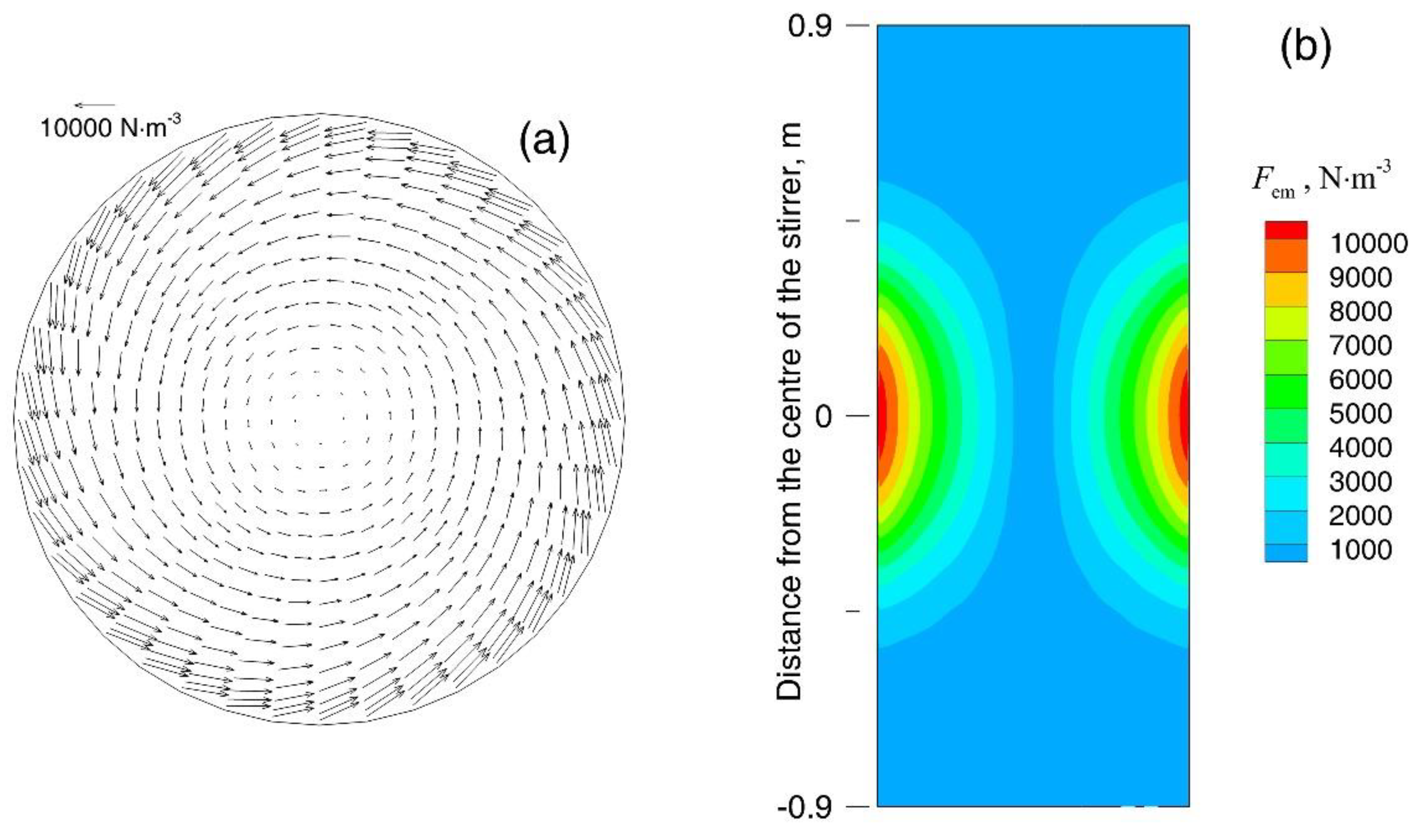
Figure 5a demonstrates the vector distribution of the time-averaged electromagnetic force density in the cross-section of the Φ600 mm round bloom. The electromagnetic force density is generally distributed circumferentially, thereby causing the rotation of the molten steel. It is greatest at the edge and decreases significantly towards the centre. Figure 5b shows the contour plot of the electromagnetic force density in the longitudinal section, which has a distribution similar to the magnetic flux density as well.
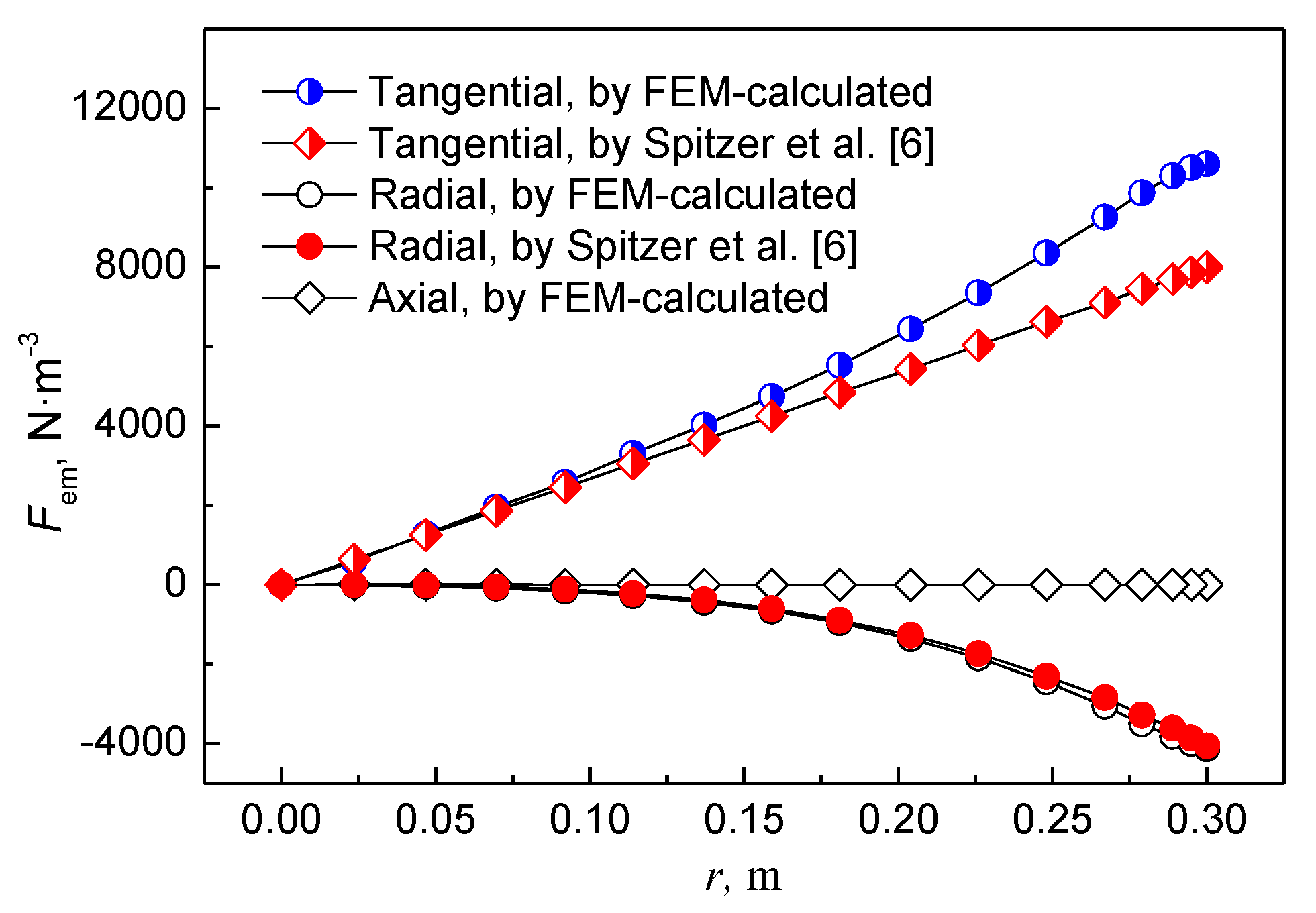
Figure 6 compares the electromagnetic force density calculated by FEM with that obtained from the analytical formula of the infinite-length stirring system deduced by Spitzer et al. [6]. Among the three components of the electromagnetic force density, the tangential electromagnetic force density is the largest, which is also the driving force of molten steel rotation. The tangential electromagnetic force density calculated by FEM is greater than that calculated by the analytical formula, especially at the edge of the strand. However, in the effective area of F-EMS on the strand (r < R/2), the difference between the two results is not large. In addition, the difference between the radial electromagnetic force densities calculated by FEM and by the analytical formula is also not large. Finally, the axial electromagnetic force density calculated by FEM is close to zero and negligible. In short, since the electromagnetic force generated by F-EMS usually acts in a region smaller than R/2 in a round bloom, it can be approximately calculated by the above analytical formula for the Φ600 mm round bloom.
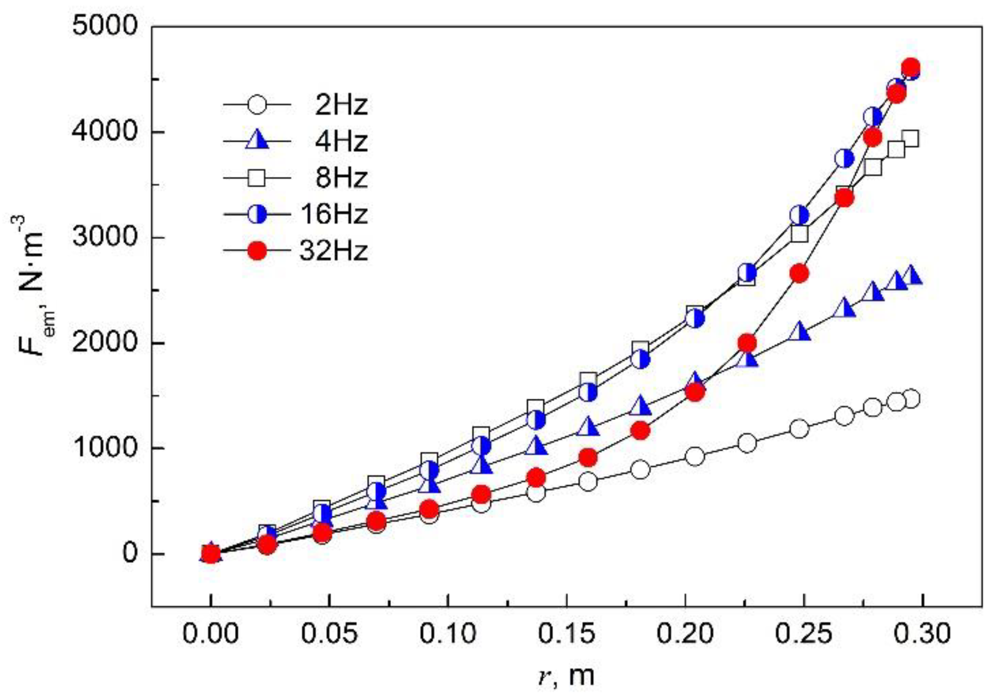
Figure 7 illustrates the variation in the electromagnetic force density in the radial direction at different current frequencies. It can be observed that when the frequency is small, the electromagnetic force density has an approximately linear relationship with the radius, which is consistent with the analytical formula [6]. However, when the frequency is greater than 8 Hz, the electromagnetic force density is no longer linear with the radius due to the ‘skin effect’.
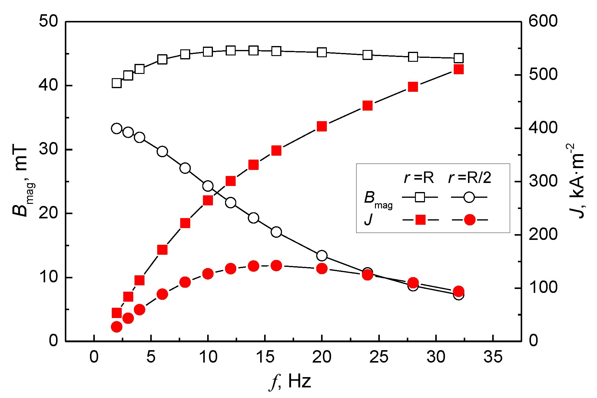
Figure 8 shows the effect of the current frequency on the magnetic flux density and induced current density. It is found that different variations appear at different positions of the Φ600 mm round bloom. At the edge of the strand (r = R), the frequency has little effect on the magnetic flux density, while the induced current density increases significantly with increasing frequency. At r = R/2 of the strand, an increase in frequency leads to a decrease in magnetic flux density, and the induced current density first increases and then decreases, and the maximum value appears at 14 Hz. Since the electromagnetic force density is the cross-product of the magnetic flux density and the induced current density, it can be inferred from Figure 8 that there is a peak in the electromagnetic force density as a function of the current frequency.
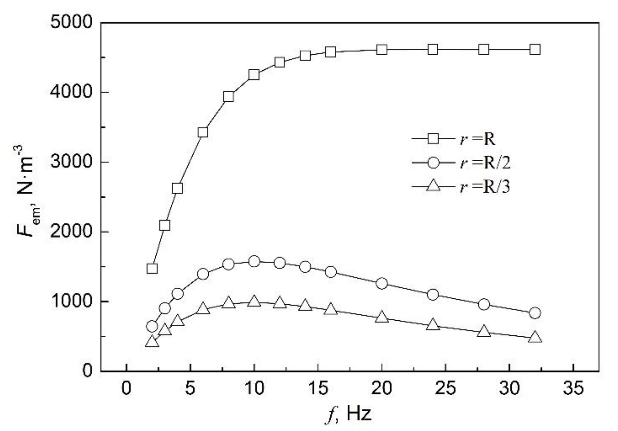
Figure 9 reveals the relationship between the electromagnetic force density and the current frequency at different radii of the Φ600 mm round bloom. At the same current intensity, the electromagnetic force density at the edge of the strand (r = R) gradually increases with increasing frequency and remains basically constant until the frequency is greater than 16 Hz. However, the electromagnetic force density at r = R/2 and R/3 of the strand reaches a maximum at a frequency of 10 Hz and then gradually decreases. Since the radius of the melt core is generally less than R/2 at the position where the strand is installed with F-EMS, the F-EMS of the Φ600 mm round bloom has the highest stirring efficiency at a frequency of 10 Hz.
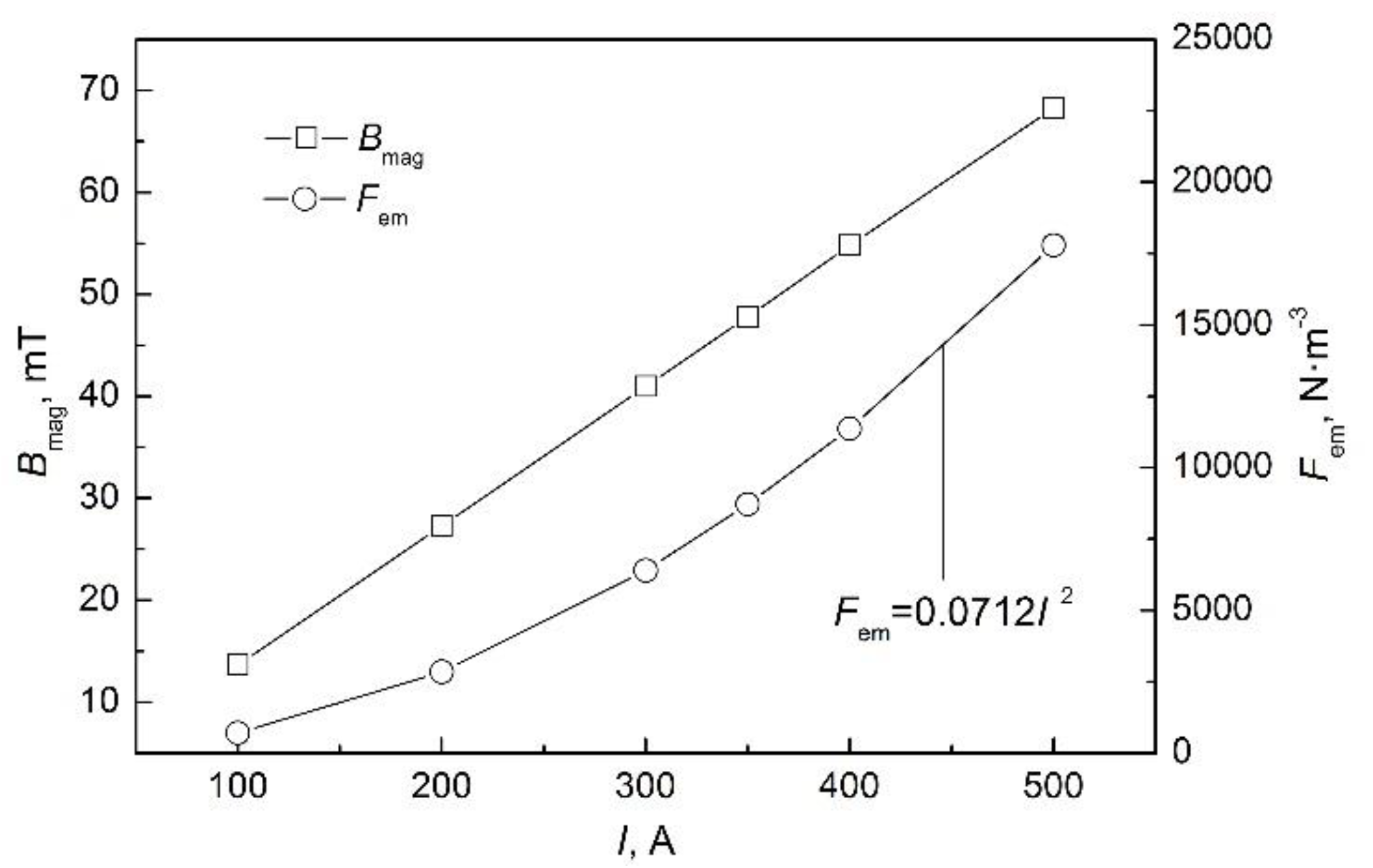
Figure 10 shows the effect of current intensity on the magnetic flux density and the electromagnetic force density. The former increases linearly with an increase in current intensity, while the latter has a quadratic relationship with the current intensity, which is consistent with the analytical formula deduced by Spitzer et al. [6].

4. Conclusions

The three-dimensional electromagnetic field in a continuous casting round bloom with F-EMS was studied numerically, and the influence of current intensity and frequency on the electromagnetic field was discussed. The following conclusions were obtained:
  • The Joule heat generated by F-EMS in a continuous casting strand is very small, and its influence on the secondary cooling heat transfer in the stirring zone can be ignored.
  • Since the electromagnetic force generated by F-EMS usually provides stirring action in a region less than R/2 of a round bloom, it is feasible to calculate it approximately using the analytical formula for the infinite-length stirring system.
  • With increase in current frequency, the electromagnetic force density at R/2 and R/3 of the strand first increases and then decreases, and it reaches a maximum at 10 Hz. The results of the calculations show that the optimal current frequency of F-EMS is 10 Hz in continuous casting of a Φ600 mm round bloom.
  • The magnetic flux density increases linearly with current intensity, while the electromagnetic force density has a quadratic relationship with current intensity.

Author Contributions

B.R., W.X., and Z.H. validated the model. B.R. performed the calculation. B.R., D.C., and H.W. analyzed and discussed the data. B.R. wrote the paper. D.C. and H.W. reviewed and edited the paper. B.R., W.X., and H.W. acquired the funding.

Funding

This research was funded by the National Natural Science Foundation of China, grant number 51674057; the Chongqing Research Program of Basic Research and Frontier Technology, grant numbers cstc2016jcyjA0142 and cstc2017jcyjAX0236; the Scientific and Technological Research Program of Chongqing Municipal Education Commission, grant numbers KJ1601326 and KJ1713343; and the Research Foundation of Chongqing University of Science & Technology, grant number CK2016B19.

Conflicts of Interest

The authors declare no conflict of interest.

References

  1. Barna, M.; Javurek, M.; Reiter, J.; Watzinger, J.; Kaufmann, B.; Kirschen, M. Continuous casting of round bloom strands with mould-electromagnetic stirring numerical simulations with a full coupling method. World Iron Steel 2012, 12, 29–33. [Google Scholar]
  2. Hanley, P.J.; Kollberg, S.G. Electromagnetic methods for continuous casting. In The Making, Shaping and Treating of Steel, 11th ed.; Cramb, A.W., Ed.; Association for Iron & Steel Technology: Pittsburgh, PA, USA, 2003; pp. 287–297. ISBN 978-0-930767-04-4. [Google Scholar]
  3. Sun, H.; Li, L.; Cheng, X.; Qiu, W.; Liu, Z.; Zeng, L. Reduction in macrosegregation on 380 mm× 490 mm bloom caster equipped combination M+F-EMS by optimising casting speed. Ironmak. Steelmak. 2015, 42, 439–449. [Google Scholar] [CrossRef]
  4. Mizukami, H.; Komatsu, M.; Kitagawa, T.; Kawakami, K. Effect of electromagnetic stirring at the final stage of solidification of continuously cast strand. Tetsu-to-Hagane 1984, 70, 194–200. [Google Scholar] [CrossRef]
  5. Xiao, C.; Zhang, J.; Luo, Y.; Wei, X.; Wu, L.; Wang, S. Control of macrosegregation behavior by applying final electromagnetic stirring for continuously cast high carbon steel billet. J. Iron Steel Res. Int. 2013, 20, 13–20. [Google Scholar] [CrossRef]
  6. Spitzer, K.H.; Dubke, M.; Schwerdtfeger, K. Rotational electromagnetic stirring in continuous casting of round strands. Metall. Trans. B 1986, 17, 119–131. [Google Scholar] [CrossRef]
  7. Vynnycky, M. On an anomaly in the modeling of electromagnetic stirring in continuous casting. Metall. Mater. Trans. B 2018, 49, 399–410. [Google Scholar] [CrossRef]
  8. Trindade, L.B.; Vilela, A.C.F.; Filho, Á.F.F.; Vilhena, M.T.M.B.; Soares, R.B. Numerical model of electromagnetic stirring for continuous casting billets. IEEE Trans. Magn. 2002, 38, 3658–3660. [Google Scholar] [CrossRef]
  9. Yu, H.Q.; Zhu, M.Y. Influence of electromagnetic stirring on transport phenomena in round billet continuous casting mould and macrostructure of high carbon steel billet. Ironmak. Steelmak. 2012, 39, 574–584. [Google Scholar] [CrossRef]
  10. Liu, H.; Xu, M.; Qiu, S.; Zhang, H. Numerical simulation of fluid flow in a round bloom mold with in-mold rotary electromagnetic stirring. Metall. Mater. Trans. B 2012, 43, 1657–1675. [Google Scholar] [CrossRef]
  11. Jiang, D.; Zhu, M. Center segregation with final electromagnetic stirring in billet continuous casting process. Metall. Mater. Trans. B 2017, 48, 444–455. [Google Scholar] [CrossRef]
  12. Marioni, L. Computational Modelling and Electromagnetic-CFD Coupling Incasting Processes; PSL Research University: Paris, France, 17 November 2017. [Google Scholar]
  13. Davidson, P.A.; Hunt, J.C.R. Swirling recirculating flow in a liquid-metal column generated by a rotating magnetic field. J. Fluid Mech. 1987, 185, 67–106. [Google Scholar] [CrossRef]
  14. Ren, B.Z.; Chen, D.F.; Wang, H.D.; Long, M.J.; Han, Z.W. Numerical simulation of fluid flow and solidification in bloom continuous casting mould with electromagnetic stirring. Ironmak. Steelmak. 2015, 42, 401–408. [Google Scholar] [CrossRef]
  15. Barna, M.; Javurek, M.; Reiter, J.; Lechner, M. Numerical simulations of mould electromagnetic stirring for round bloom strands. Berg Huettenmaenn. Monatsh. 2009, 154, 518–522. [Google Scholar] [CrossRef]
  16. Mao, B.; Ren, B.; Han, Z.; Cao, J.; Feng, K. Numerical simulation for heat transfer during solidification of round bloom continuous casting. Ind. Heat. 2012, 41, 50–53. [Google Scholar] [CrossRef]
  17. Guo, G.; Ma, H.; Zhang, J.; Huang, L. The relationship of thermophysical properties to microstructure of high-carbon steel. Phys. Test. Chem. Anal. 2006, 42, 167–170. [Google Scholar]
  18. Long, M.; Dong, Z.; Sheng, J.; Chen, D.; Chen, C. Universal secondary cooling structure for round blooms continuous casting of steels in various diameters. Steel Res. Int. 2015, 86, 154–162. [Google Scholar] [CrossRef]
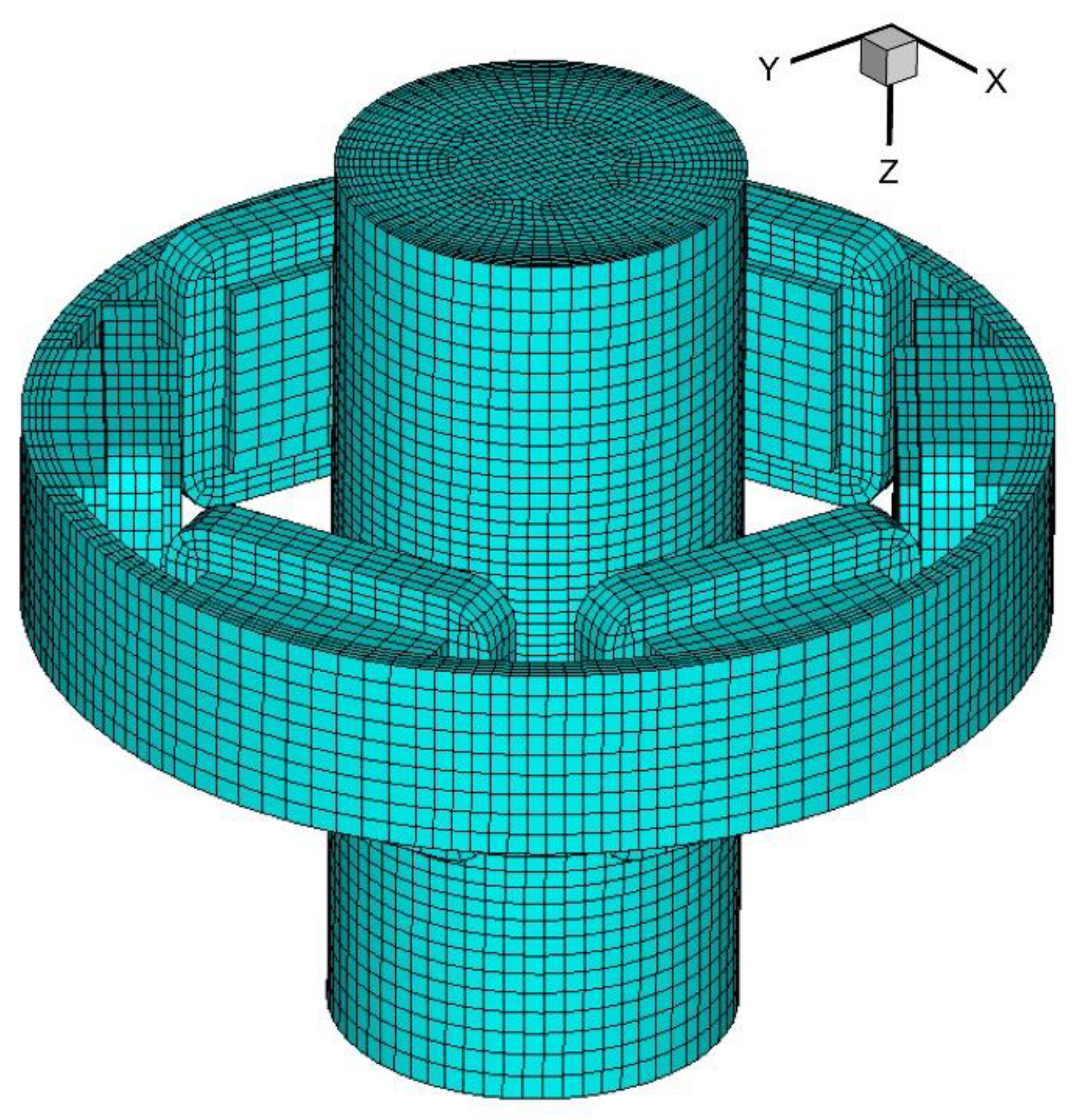
Figure 1. Schematic illustration of final electromagnetic stirring (F-EMS) for round bloom continuous casting. The air cylinder is not shown.
Metals 08 00903 g001
Figure 2. Profile of the magnetic flux density along the axial direction for I = 350 A and f = 4 Hz.
Metals 08 00903 g002
Figure 3. Contour plot of the magnetic flux density in the (a) cross-section and (b) longitudinal section for I = 400 A and f = 4 Hz.
Metals 08 00903 g003
Figure 4. Contour plot of the time-averaged Joule heat power density in the (a) cross-section and (b) longitudinal section for I = 400 A and f = 4 Hz.
Metals 08 00903 g004
Figure 5. Distribution of the time-averaged electromagnetic force density in the (a) cross-section and (b) longitudinal section for I = 400 A and f = 4 Hz.
Metals 08 00903 g005
Figure 6. Comparison of FEM-calculated electromagnetic force density with that of the analytical solution by Spitzer et al. [6] in the middle plane of the stirrer for I = 400 A and f = 4 Hz.
Metals 08 00903 g006
Figure 7. Electromagnetic force density profile as a function of radial distance at the middle plane of the stirrer for various current frequencies and I = 200 A.
Metals 08 00903 g007
Figure 8. Effect of current frequency on the magnetic flux density and the induced current density at the middle plane of the stirrer for I = 200 A.
Metals 08 00903 g008
Figure 9. Effect of current frequency on the electromagnetic force density at different radii for I = 200 A.
Metals 08 00903 g009
Figure 10. Effect of current intensity on the magnetic flux density and the electromagnetic force density at the middle plane of the stirrer for f = 4 Hz.
Metals 08 00903 g010