Article

Iron Metallurgy via Concentrated Solar Energy

by
Daniel Fernández-González
1,*,
Janusz Prazuch
2,
Íñigo Ruiz-Bustinza
3,
Carmen González-Gasca
4,
Juan Piñuela-Noval
1 and
Luis Felipe Verdeja González
1
1
Departamento de Ciencia de los Materiales e Ingeniería Metalúrgica, Escuela de Ingeniería de Minas, Energía y Materiales, Universidad de Oviedo, 33004 Oviedo, Asturias, Spain
2
Department of Physical Chemistry and Modelling, Faculty of Materials Science and Ceramics, AGH University of Science and Technology, 30-059 Krakow, Poland
3
Departamento de Ingeniería Geológica y Minera, Escuela Técnica Superior de Ingenieros de Minas y Energía, Universidad Politécnica de Madrid, 28003 Madrid, Spain
4
Escuela de Doctorado e Investigación, Universidad Europea de Madrid, 28670 Villaviciosa de Odón, Madrid, Spain
*
Author to whom correspondence should be addressed.
Metals 2018, 8(11), 873; https://doi.org/10.3390/met8110873
Submission received: 5 September 2018 / Revised: 20 October 2018 / Accepted: 23 October 2018 / Published: 25 October 2018

Abstract

:
Environmental protection is deeply rooted in current societies. In this context, searching for new environmentally friendly energy sources is one of the objectives of industrial policies in general, and of the metallurgical industries in particular. One of these energy sources is solar energy, which offers a great potential in high temperature applications, such as those required in metallurgy processes, when properly concentrated. In this paper, we propose the utilization of concentrated solar energy in ironmaking. We have studied the utilization of concentrated solar thermal in the agglomeration of iron ore mixtures and in the obtaining of iron via reduction with carbon (and coke breeze). The results from the experiments show the typical phases of the iron ore sinters and the presence of iron through smelting reduction.

1. Introduction

Iron (steel) is one of the most important metallic and nonmetallic materials. Statistics indicate that more than 1600 Mt of crude steel were produced in 2016 (Steel Statistical Yearbook 2017) [1]. Oxygen blow converter technology (via blast furnace, BF) accounted for 72% of steel production in 2013 [2], followed by electric furnace technology (27.5% [2]) and open-hearth furnace technology (0.5% [2]). New alternative processes are gaining more interest, especially those based on the (DRI) direct reduction of iron ores (agglomerated) in the presence of a reducing gas or gasified carbon, but these technologies are still not important in production [2]. Among these alternative processes, the Midrex (developed in 1950 by the Midland Ross Corporation (Cleveland, OH, USA), which was bought in 1984 by Kobe Steel (Kobe, Japan)) is the most important when it comes to production (47.14 Mt in 2016 according to Midrex Stats).
Concentrated solar energy offers a great potential in high temperature applications [3]. These applications include [3]: Materials processing (welding and cladding, surface treatments, coatings and surface hardening, and powder metallurgy), synthesis and treatment of nonmetallic materials (ceramics, fullerenes, carbon nanotubes, calcium aluminate cements [4], and production of lime), and metallurgical processes (production of silicon and aluminum, ZnO/Zn couple as chemical combustible). Concentrated solar thermal has still not been widely applied in iron- and steelmaking. Ruiz-Bustinza et al. studied the treatment of mill scale (which is produced in quantities of approximately 5 kg of mill scale per ton of steel) in a fluidized bed furnace heated with concentrated solar energy, and they obtained Fe3O4 free of contaminants, to be used in the production of high-quality steel or as feedstock for aluminothermic welding of railway rails [5]. Other research was performed to study the effect of concentrated solar energy in iron oxides. In this way, Sibieude et al. studied the decomposition of magnetite at temperatures above the melting point of this phase in the presence of air and argon atmospheres [6]. Steinfeld and Fletcher [7] studied the reduction of iron oxide (III) with graphite as a reducing reagent in a solar furnace at high temperatures (1300–2390 K), with Fe yields of 78%. Steinfeld et al. explored the coproduction of iron and synthesis gas by reduction of magnetite with CH4 [8]. Mochón et al. studied the carbothermal reduction of iron oxide (III) and manganese oxide (IV) [9].
The iron and steelmaking industry is one of the biggest emitters of CO2. Between 4% and 7% of anthropogenic CO2 comes from this industry in the EU27 [10]. In the case of world emissions, the iron and steelmaking industry accounted for an estimated of 4.1% of total CO2 emissions, and about 3.2% of all GHGs (Greenhouse Gases) in 2000 [11]. Individualizing the emissions to the processes of ironmaking, 19.6% of the CO2 emissions come from the sintering machine and 62% from the blast furnace, according to Ariyama and Sato [12]. In the case of the blast furnace, the consumption of coke has been reduced from 800 kg/t Hot Metal in the 1960s to 470 kg/t HM in the 2010s (although consumptions were reduced to 396 kg/t HM under specific conditions in Japan [13]). The roles of coke in the blast furnace are three [14]: Physical/mechanical—the coke must resist the burden at high temperature under a reducing environment (apart from having a suitable porosity for the circulation of the gases); chemical—the coke reacts with CO2 to produce CO, which reduces the burden, according to the Boudouard mechanism; and thermal—the heat produced by coke combustion must be enough to favor the reactions and keep in molten state the metal and the slag in the lower part of the furnace. In the case of the electric arc furnace (EAF) route, electric power is used as a heat source (310–640 kWh/t steel [15]), while coke is mainly used as a reductant. In the sintering process, coke is mixed with the material to be sintered and provides heat when combusting. The emissions of carbon dioxide in these processes are: BF-BOF (Blast Furnace-Basic Oxygen Furnace) based steel production reported in the range 1630–1960 kg/t steel [15], 200 kg/t sinter [16], and 560–1450 kg/t steel for the raw steel production in EAF [15]. In all these processes, coke used to reduce the burden cannot be eliminated and CO2 emissions in this way cannot be avoided. However, the coke or the electricity used to produce heat could be replaced with concentrated solar energy and, in this way, lead to reducing carbon dioxide emissions.
In this paper, we will study two alternative processes to conventional sintering in the Dwight-Lloyd machine, and the production of iron in the BF and in the EAF. Thus, the objectives are: agglomerating mixtures of iron ore, such as those used in the sintering process; synthesizing iron through reduction of iron oxide (III) in the presence of carbon; and smelting reduction of iron ore sinter with coke breeze, using concentrated solar energy in the three processes. This way, carbon dioxide emissions could be reduced in ironmaking by replacing the heat generated by the carbon with solar energy.

2. Solar Agglomeration of Iron Ore

The agglomeration of iron ore using concentrated solar energy is the first process proposed in this paper. The objective is to agglomerate an iron ore mixture like that treated in the sintering machine. The sintering process is defined as a thermal agglomeration process (1300–1400 °C [17], but it does not involve the complete melting of the charge) that is applied to a mixture of iron ore fines, recycled products, slag-forming elements, and coke, with the purpose of obtaining a product with suitable composition, quality, and granulometry to be loaded into the blast furnace [2,18,19,20,21,22]. The iron ore sintering process was deeply reviewed by the authors of [2,18,19,20,21,22], so if further information about the sintering process is required, we suggest reading their work.
In conventional iron ore sintering, mixtures of mineral fines, return fines, fluxes, and recycled products are treated in the presence of coke dust. A burner initializes the mixture and the heating progresses from the upper to the lower sections, due to the downdraught suction of the gases. The process is performed in a continuous manner with a moving grate (Dwight-Lloyd system) and, thus, the flame front progresses as an inclined line that has one of the borders at the end of the strand and the other in the initializing system. This way, gases pass through the charge, and the process progresses. Sinter strands usually comprise two layers, the lower of coarse granulometry (10–20 mm) (layer of 30–60 mm) and then the upper of fine material (0–8 mm), to make a bed height of 500–600 mm that is sintered in approximately 25 min [23]. In addition, the fine material is granulated before being disposed in the sinter grate. In this way, a permeable structure (with interlinked porosity) is developed, and the gases can circulate through the charge.
In our proposal for the agglomeration process, we operated in a stationary state. Mixtures to be agglomerated were loaded into a crucible and subjected to the heating system (concentrated solar energy). There was no downdraught suction, and thus gases did not circulate through the load. This question limited the depth of the treated material. Hot gases in the industrial process, including CO2, circulate through the load, and they preheat the load, initialize the combustion of the coke in lower layers, partially reduce the iron ore, and favor other reactions of dehydration, calcination, and reduction.

2.1. Materials and Methods

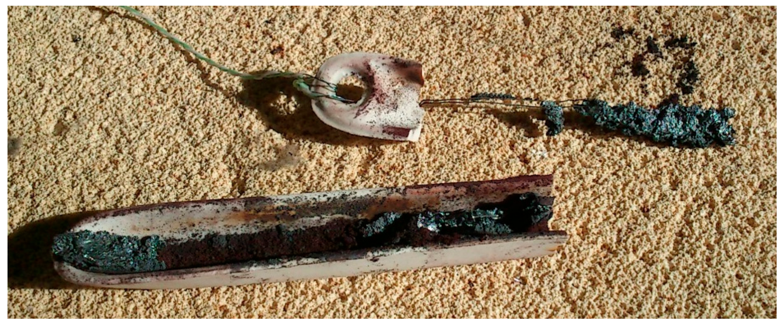
Experiments were performed in a 1.5 kW vertical axis solar furnace located in Odeillo (France) and belonging to the Centre National de la Recherche Scientifique (PROMES-CNRS). This solar furnace has a heliostat that tracks sunlight and directs it towards a parabolic concentrator of 2.0 m in diameter (Figure 1). The parabolic concentrator makes radiation converge in a focal point of 15 mm in diameter. The maximum concentration that can be reached is 15,000 times the incident radiation. Mixtures were loaded in tabular alumina crucibles (55 mm height, 30 mm upper diameter, 25 mm lower diameter, and 3 mm in thickness) that were located below the focal point (see Figure 2a). The duration of the experiments varied between 12 and 20 min, depending on the sample. The sample was held below the focal point throughout the experiment. Tests were performed under air atmosphere. However, a glass hood connected to a pump was used to catch gases and particles released during the experiments, which otherwise could become adhered to the parabolic concentrator (Figure 2b). The same mixtures were used in the five experiments, with the purpose of reproducibility. Mixtures were prepared with sinter mixture (sinter feed Voestalpine, see Table 1, d50 < 2 mm) and 2 mass % of coke breeze (see Table 2, d50 < 1 mm). They were manually mixed and homogenized, and then mixtures were charged into the crucible. The Voestalpine sinter feed, the same as the coke breeze, is that used in the industrial iron ore sintering process in the Dwight-Lloyd machine (but we only used the fine granulometric fraction). However, the sinter mixture was not granulated in our experiments, as fluid-dynamics (solid-gas interaction) did not require it.
A thermocouple was located outside and at half height of the crucible (Figure 2a,b). This thermocouple was used to control the progress of the process. This way, it is assumed that the reaction has reached the height of the thermocouple when the temperature remains stable at this point. In that moment, the sample is removed from the focal point and is air-cooled. Incident solar radiation values were similar in all experiments except for the sample Sint1 (see Table 3). In the case of Sint1, the experiment was stopped because of the unsuitable weather conditions, and later it was restarted when weather conditions were adequate.
The power applied to the sample was controlled by means of the shutter opening (0, closed; 100, totally opened), the power being progressively applied. The objective of this progressive heating was to avoid violent reactions, and thus, reduce the losses of material due to projections. In addition, the solar beam could be located exactly in the center of the free surface of the charge, and thus, lead to minimizing the charge/crucible interactions.

2.2. Results and Discussion

A total of five mixtures were agglomerated using concentrated solar energy. Experimental conditions are collected in Table 3 and Table 4.
Mass losses are related with the volatile phases and some reaction products. They can be summarized in water (both of moisture and crystallization (chemically bonded)), part of the phosphorus and sulfur, part of the alkalis, and mainly carbon (available both in the coke and the sinter) as oxide. Dehydration, calcination, and reduction reactions also produce mass losses. Finally, projections of material due to the violent reactions during the treatment, as well as fine particles carried with the hot gases, are unavoidable. Table 3 shows the mass losses produced in each experiment (>20%).
A piece of approximately 20 mm in diameter and 12–15 mm in height was removed from the crucible. The rest of the material available in the crucible was only heated, but not enough to react or to be agglomerated. Samples for X-ray diffraction analyses were taken from these pieces (pieces of the same zone were used in SEM-EDX (Scanning Electron Microscopy with Energy Dispersive X-ray Spectroscopy) observations (Faculty of Materials Science and Ceramics, AGH University, Krakow, Poland)). They were crushed and milled, and the powders were used for X-ray diffraction analyses. X-ray diffraction measurements of powdered samples were conducted with Empyrean PANalytical diffractometer (Faculty of Materials Science and Ceramics, AGH University, Krakow, Poland) using Kα1 and Kα1 radiation from Cu anode. All measurements were performed with a Bragg-Brentano setup at room temperature, with 0.006° step size at 5–90° 2θ scanning range and 145 s of measurement time for each step. Data analysis and the peak profile fitting procedure were carried out using XPowder12 Ver. 01.02 (Database PDF2 (70 to 0.94), Escuela de Ingeniería de Minas, Energía y Materiales, Universidad de Oviedo, Oviedo, Asturias, Spain). The X-ray diffraction patterns are displayed in Figure 3, Figure 4, Figure 5, Figure 6 and Figure 7.
From the X-ray diffraction analyses, we can see that iron oxides (FeO and Fe3O4) are the most representative phases, as expected. Silicoferrites of calcium (but also aluminates and ferrites) are also available in the samples. A quantitative analysis of the crystalline phases was performed using the software XPowder12 Ver. 01.02. The results are shown in Table 5.
The power was applied progressively to minimize the projections and to achieve a progressive heating of the mixture to be sintered. In this way, the typical sequence of the sintering industrial process reactions could be verified [19]: cold and wet zone (<100 °C, which in our case would be significantly short, seconds), drying zone (100–500 °C, which in our case would correspond to low power values, vaporization of moisture, and dehydration reactions, seconds), reaction zone (maximum temperatures, >1400 °C, reactions involved in the formation of part of the phases detected during the X-ray diffraction analyses), and cooling zone (after the removal of the solar beam, recrystallization reactions). However, and as mentioned, our process of solar agglomeration of iron ore mixtures had no downdraught suction and this presented an impediment to the hot gases passing through the load to satisfy the abovementioned reactions in all the material loaded in the crucible. Another problem that should be considered is that the size of the particles to be agglomerated in our experiments is <2 mm. The industrial sintering process uses particles of different sizes to form channels for the circulation of the gases. In fact, the circulation of the gases in the sintering process is a well-studied parameter [19], and different models of sinter bed structure have been studied (MEBIOS, RF-MEBIOS, etc.) [24,25]. These channels create a ventilation route for the gases in the sintering process, but also a suitable structure of pores for the subsequent load as burden in the blast furnace. One of the advantages of the industrial sintering process is partial melting, which allows the development of the typical sinter phases and defines the adequate structure of voids and pores for the subsequent load in the blast furnace. Unfortunately, during our experiments of iron ore agglomeration, downdraught suction was not used, but also partial melting was not achieved. The sample was completely melted in the surface in contact with the solar beam and in a depth of 12–15 mm. The presence of liquid (due to the complete melting of part of the material) filled the empty spaces, destroyed the interlinked porosity, and created a crust of material in the surface in contact with the power source. The lack of voids, pores, and interlinked porosity, together with the lack of downdraught suction of the gases, impeded the progress of the process until reaching the bottom of the crucible. Under these conditions, the agglomerated material only reached around 12–15 mm in depth and, below this crust, the material remained unreacted at the end of the process. The lack of porosity (and particularly interlinked porosity), together with the lack of circulation of gases/air through the load, impeded the oxidation of the wüstite formed during the process, and this explains the large amount of wüstite in the final product.
Concentrated solar energy is a powerful energy source. A better control of the power would be necessary to achieve the partial melting of the charge and not the full melting. Moreover, to approach the industrial sintering practice, we should also use the downdraught system to allow the circulation of the gases through the load. Obviously, lower values of power should be used to impede the full melting of the load. In addition, coke should be eliminated from the mixtures to be sintered if we really want to reduce CO2 emissions, as otherwise the paper of the solar energy would be limited to only initializing the mixture and the reductions in the emissions would be small. In this way, solar energy should be the source of heat for the agglomeration and not only the initializing system.
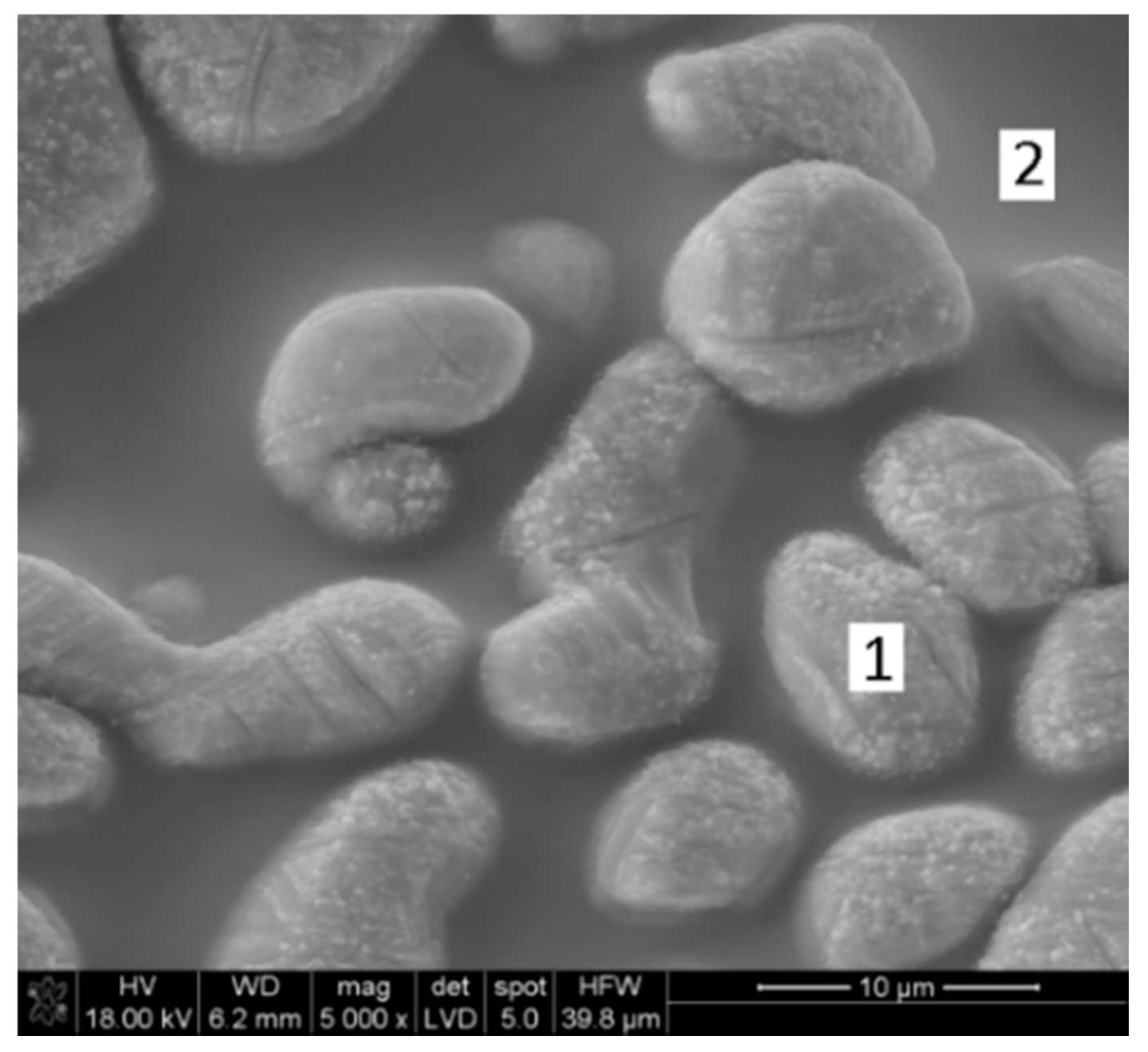
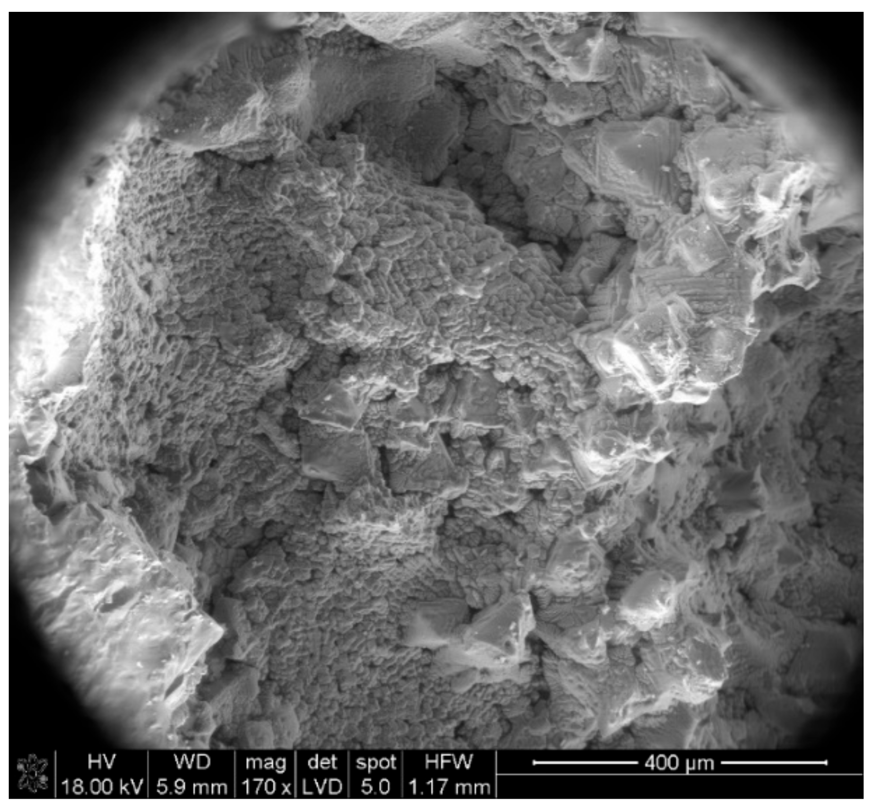
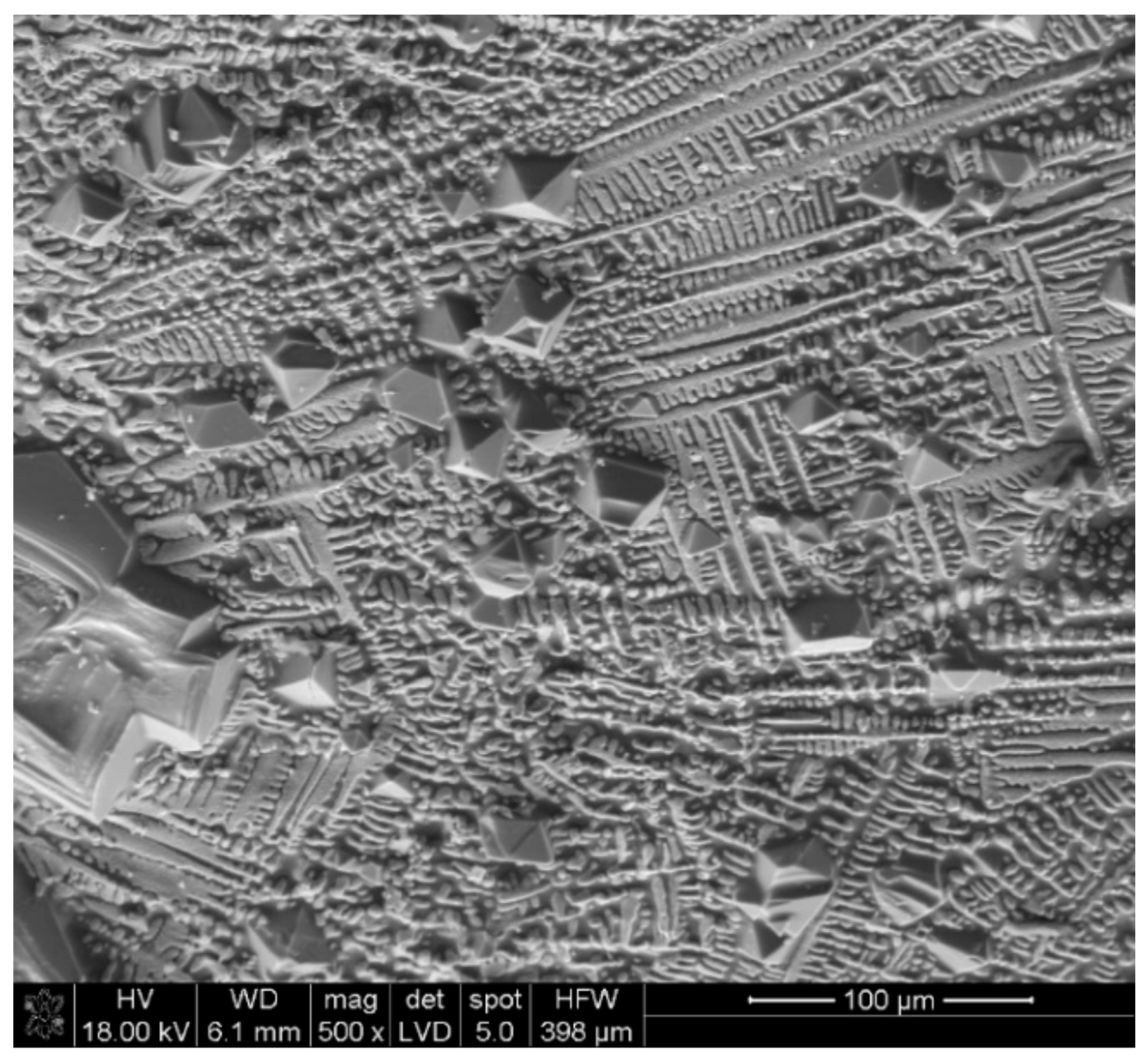
Samples were also observed with the electronic microscope, with the possibility of performing point analysis. Figure 8 shows a representative image of the solar sintered samples, where point 1 (disperse constituent) corresponds to the iron rich phase (Table 6), while point 2 (matrix constituent) belongs to the silicoferrites of calcium and aluminum (Table 6). In Figure 9, it is possible to see, at lower magnification, the structure shown in Figure 8. Figure 9 shows that the process develops in a larger extent and not only locally.
The iron rich phases are the wüstite and the magnetite (Fe3O4). There is no hematite in the final product. Hematite is a typical phase in the iron ore sinter, main constituent together with the SFCA (Silicoferrites of Calcium and Aluminum). Hematite usually appears in the sinter as primary (from the original sinter) and secondary (from crystallization of a molten phase: Oxidation of magnetite or direct crystallization). The quantity of primary hematite is reduced with the increase of the temperature, while, on the contrary, the presence of secondary hematite is increased—the same as the presence of magnetite. As previously mentioned, the volume of material agglomerated involves approximately the diameter of the crucible and a depth of approximately 12–15 mm. The porosity of this agglomerated material is small, and the interlinked porosity is almost nonexistent. The lack of both downdraught suction and interlinked porosity impedes the circulation of gases/air through the load, and apart from making it impossible to treat all the material available in the crucible, impedes the reoxidation of the iron oxides. This way, the sample mainly comprises wüstite instead of iron oxide (III) and magnetite, as in the typical iron ore sinters obtained in the industrial process [19,20]. Changing the structure of the sample (for example, large particles as core with fines) or changing the heating time could have a positive effect on the results.
Other important phases in the final product are the calcium ferrites. A single composition for ferrites cannot be stablished due to the partial replacement of Ca2+ by Mg2+, Fe2+ by Mn2+, Fe3+ by Al3+ and Si3+, etc. Consequently, we can give the name of calcium ferrites (silicoferrites of calcium and aluminum can be included in this group) several chemical compounds that are formed by crystallization of the liquid phase, although the mechanism is not well understood [26]. The base-acid reactions are a possible explanation for the formation of these compounds, because wüstite is more basic than the oxides of calcium, aluminum, and silicon [27].
The utilization of concentrated solar energy in the agglomeration of iron ore mixture was studied in this section. The reduction in the carbon dioxide emissions in the sintering process can be achieved through two routes: Replacing the initializing system and/or reducing/eliminating the coke mixed with the iron ore to be agglomerated. Replacing the initializing system could reduce the emissions, but the effect on the environment would be almost insignificant. Reducing/eliminating the coke mixed with the iron ore is the option that could reduce carbon dioxide emissions more in the sintering process. In this way, solar energy should replace the heat provided by the combustion of the coke. This requires a suitable control of the heat supplied by the concentrated solar energy beam. The reason is that the temperature reached in all points of the mixture to be sintered should be the same, to obtain a homogeneous sinter. If the temperature was high enough in the upper layer (as in our experiments), the upper layer would melt, the liquid would fill empty spaces, the interlinked porosity would be destroyed, and the process would be blocked. Moreover, a nonporous material cannot be used in the blast furnace, as the process in that furnace is also based on the circulation of gases. It seems very difficult that a punctual heat source could ensure a homogeneous distribution of the heat in the charge. This question limits the potential application of concentrated solar energy in the sintering process or in any other iron ore agglomeration process.

3. Solar Synthesized Iron

3.1. Theoretical Basis

The mechanisms of the iron ore reduction are two [28]:
1. Direct reduction with carbon or coke:
FexOy (s) + C(s) = FexOy−1 (s) + CO(g),
in which x = 1, 2, or 3 when y = 1, 3, or 4. Reaction (1) can be used in thermodynamic calculations (free energy or enthalpy). However, Reaction (1) does not proceed with significant conversions of iron oxide into iron, as solid-solid reactions are not kinetically as favorable as solid-gas reactions [29]. In fact, direct reduction of iron oxides is affected by the Boudouard mechanism and the reduction progresses as the second mechanism that is described as follows:
2. Indirect reduction with gas:
FexOy (s)+ CO(g) = FexOy−1 (s) + CO2(g),
CO2(g)+ C(s) = 2CO(g),
in which x = 1, 2, or 3 when y = 1, 3, or 4.
Apart from a negative value of the free energy, an excess of reductant reagent is required to achieve the total conversion of the load. The reaction speed in heterogeneous systems is related with the following parameters:
  • Nature of the substances, which is related with the structure and energy of the phases involved in the reaction;
  • Concentration of the reagents, which affects the surface chemical process and the transportation rate;
  • Temperature (the higher the temperature, the bigger the reaction ratio will be);
  • Interphase surface;
  • Geometry of the interphase;
  • Nature of the interphase;
  • Presence and characteristics of the reaction products in the interphase.
The process described in this section progresses in accordance with Equations (2) and (3) [28,29,30], in the presence of molten phase. The rate of this two-stage mechanism is controlled by the carbon monoxide formation prior to reacting with the iron oxide [28,29,30]. At temperatures above 1100 °C, the rate of reduction of the iron oxide is comparable to the rate of the carbon oxidation, while the oxidation of the carbon is considerably slower than the reduction of the iron oxide at temperatures below 1100 °C [30]. The reduction of the Fe2O3 to FeO will be faster than that of FeO to Fe, as described by Fruehan [30], because the CO2/CO equilibrium ratio is higher, and this (together the lack of reducing atmosphere) explains the difficulty in obtaining Fe in the solar furnace. The solar furnace allows to easily reach temperatures higher than 1500 °C, and thus we propose the reduction of hematite with carbon, and the smelting reduction of iron ore sinter with coke breeze.

3.2. Smelting Reduction of Hematite with Carbon

3.2.1. Materials and Methods

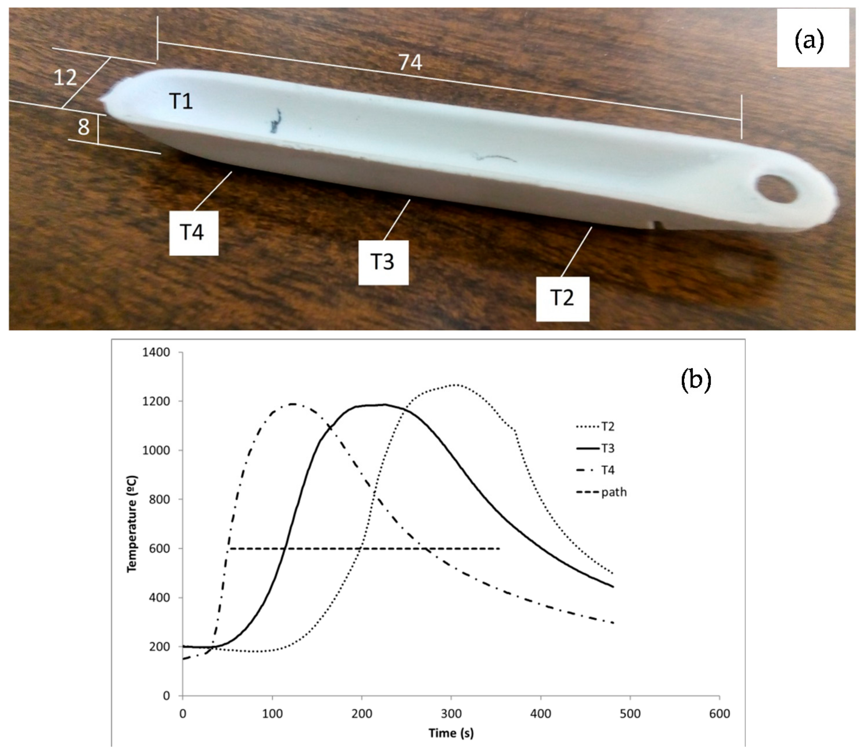
Experiments were performed in a 1.5 kW vertical axis solar furnace located in Odeillo (France), and belonging to the Centre National de la Recherche Scientifique (PROMES-CNRS) (the same solar furnace was used in all experiments). This solar furnace has a heliostat that tracks sunlight and directs it towards a parabolic concentrator of 2.0 m in diameter (Figure 1). The parabolic concentrator makes the radiation converge in a focal point of 12 mm in diameter. The maximum concentration that can be achieved is 15,000 times the incident radiation. The control of the radiation is performed using a shutter that allows to employ different fractions/percentages of the incident radiation (0, shutter closed; 100, shutter totally opened). The temperature was registered using four K-type thermocouples located in different positions (see Figure 10a). The thermocouple T1 is located inside the crucible and its measurements are not useful, because it moves due to the reaction of the charge and also because it is burnt at the temperatures involved in the process. The measurements of the thermocouples T2, T3, and T4 are indirect measurements because they are located in different positions outside the crucible (see Figure 10a). However, the measurements of the thermocouples T2, T3, and T4 provide information about the progress of the process (see Figure 10b). One of the main features of the solar furnaces, the fast heating rate up to the maximum temperature, is shown in the Figure 10b. However, the samples were air-cooled after being removed from the solar energy beam.
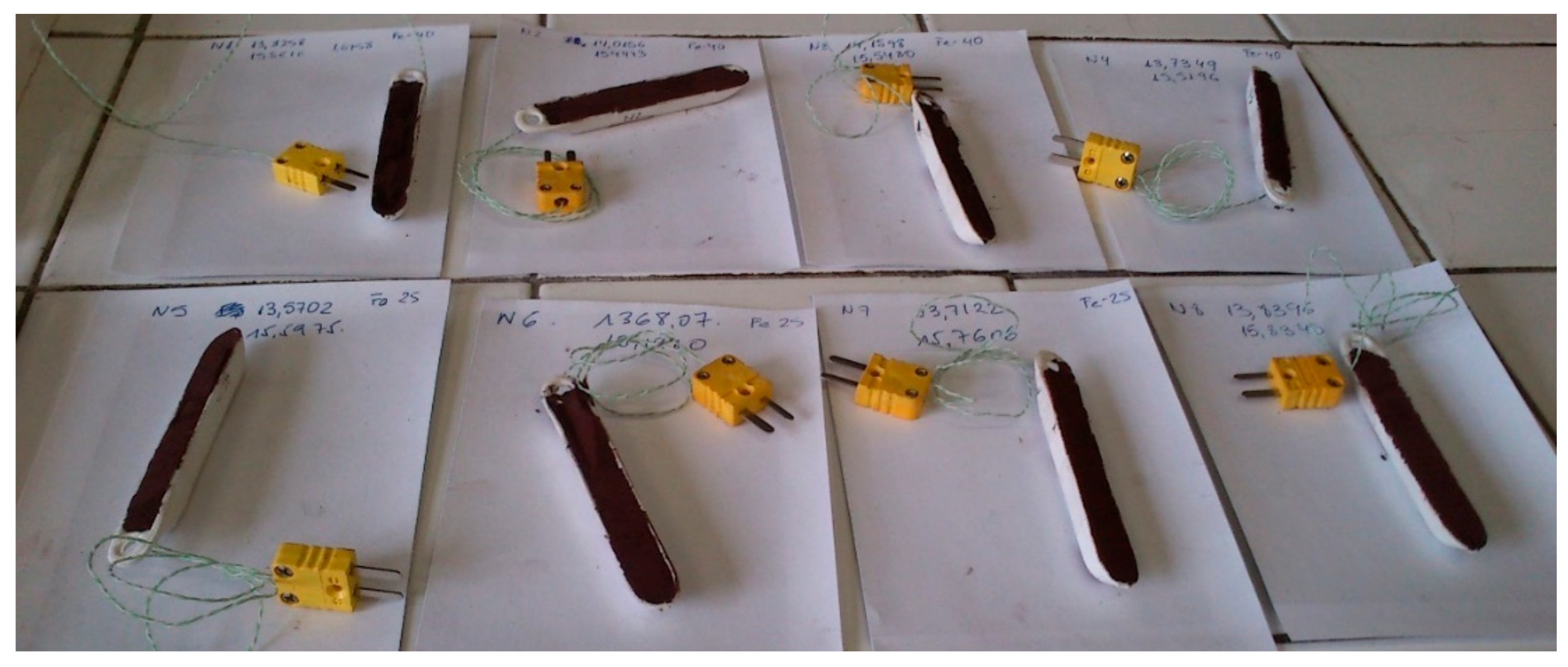
Different mixtures were prepared using pure laboratory reagents, hematite powder (Fe2O3, Prolabo (Rectapur) with d50 of 6.7 µm, Fe2O3 ≥ 97%) and carbon powder (10.2 µm (d50)). Carbon was added with different excesses over the stoichiometric requirements calculated according to Equation (1): 10%, 25%, and 40%. Samples were loaded into mullite crucibles of 75 mm length, 12 mm width, and 8 mm depth (Figure 10a), with subsequent manual compaction to avoid projections of material and facilitate the contact between particles (see Figure 11).
Samples were located below the focal point (12 mm in diameter) and displaced at a controlled speed. Experiments were performed under air atmosphere with no control of the flow (glass hood shown in Figure 1 was used to protect the parabolic concentrator from the fine particles carried by the gases that otherwise could become adhered to the parabolic concentrator). In this way, the following variables were controlled:
  • Power, which is controlled with the shutter (between 725 and 1160 W);
  • Displacement speed below the solar beam (0.25 to 0.75 mm/s);
  • Ratio iron oxide (III) to carbon (10, 25 and 40% carbon over the stoichiometric).
Fifteen samples were obtained. Conditions are collected in Table 7 and Table 8. Final mass was calculated in the samples where projections were not detected, although similar results should be expected in these cases, as conditions were similar.

3.2.2. Results and Discussion

Samples taken from the reacted zone were analyzed using the X-ray diffraction technique. A quantitative analysis of the crystalline phases was performed using the software XPowder12 Ver. 01.02. The quantities of the crystalline phases Fe2O3, Fe3O4, FeO, Fe, and Al6Si2O13 (mullite) are shown in Table 9.
The iron oxides from the less to the more reduced are: Fe2O3, Fe3O4, FeO, and Fe. The presence of phases different from the initial hematite (Fe2O3) indicates that the initial mixture was partially reduced. However, metallic iron was only detected in the samples E20 P1 (Figure 12), E20 P2 (Figure 13), E20 P3 (Figure 14), and E20 P4 (Figure 15). As described by Fruehan, the reduction rate of Fe2O3 to FeO is faster than that of FeO to Fe [30]. Magnetite, Fe3O4, and wüstite, FeO are the main phases in most of the samples. Hematite (Fe2O3) was detected in most of the samples. This hematite can be classified into two categories [20]: Primary, which comes from the original mineral (hematite that was not reduced); secondary or recrystallized, which is obtained by crystallization of the molten phase through direct crystallization, oxidation of magnetite crystals, or oxidation of magnetite crystals in solid phase. Magnetite is formed by the reduction of the initial hematite in the presence of the carbon or by thermal decomposition of the hematite at the involved temperatures (ΔG0 < 0 at temperatures above 1350 °C). Wüstite is formed by precipitation from the liquid in low potential of oxygen, and also obtained by reduction of hematite and magnetite in the presence of carbon.
Al6Si2O13 (mullite) was detected in some samples in the X-ray diffraction analyses. The temperature was sufficiently high to soften/melt the crucible, and this explains the detection of mullite during the X-ray diffraction analyses, as well as the detection of aluminum and silicon in the SEM–EDX analyses (as we will see later). If we compare the results displayed in Table 9 with the conditions shown in Table 8, we can see that metallic iron was detected in the samples with the lowest values of power. By contrast, mullite was detected in the samples with the highest values of power. From this comparison between Table 8 and Table 9, it is possible to deduce that the highest values of power provide the highest quantities of magnetite. The decrease in the reduction ratio when increasing the heat available is explained as follows: FeO is a basic oxide while Al2O3 and SiO2 are more acid than the first one (especially SiO2), and, in this way, silicates and aluminates are formed due to base-acid reactions. This reaction is favored by the temperature. As iron oxide is consumed in reacting with the phases of the crucible, it is not reduced, and the reduction ratio is decreased. If the crucible was cold (as in E20 P1, E20 P2, E20 P3, and E20 P4), bigger quantities of iron oxide would be obtained, and iron oxide (III) could be reduced even until metallic iron was obtained.
Figure 16 shows the macroscopic appearance of one sample—in this case, one of the samples where iron was detected. The red/brown color zones indicate that a certain quantity of material was not treated (cold crucible). The brilliant grey agglomerated material corresponds to the treated material, which can be easily removed from the crucible in this case. In this way, the final product is a porous material where only iron oxides and iron are detected.
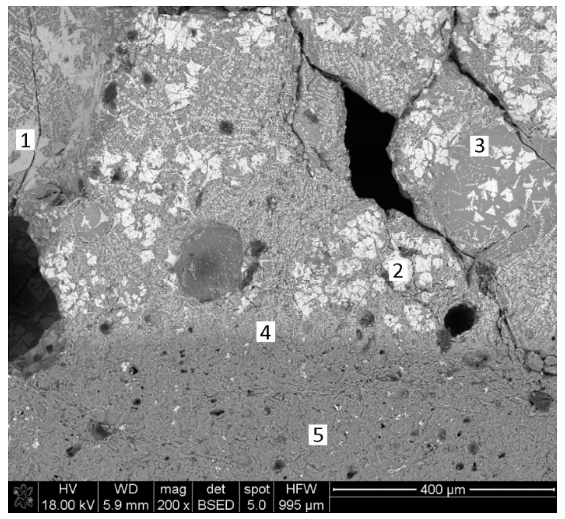
As we have previously mentioned, there is crucible/charge adherence and interaction when the maximum powers are used. The crucible/charge interaction promotes diffusion/reaction mechanisms and silicon and aluminum move into the charge because both crucible and charge are melted. The charge (iron oxides) is bonded by a phase that comprises the elements/phases of the crucible, but also the iron oxides of the charge. The result is a product strongly adhered to the crucible due to the presence of molten phase, but also a product without voids and pores. This last question can be checked through SEM-EDX analysis. Figure 17 shows the SEM image of the sample E25P2, while the point analysis results for this sample are collected in Table 10. Points 1, 2, and 3 belong to the charge. Point 4 corresponds to the charge/crucible interphase. Point 5 informs about the crucible. Aluminum, silicon, and potassium should not appear in the charge because the initial mixture comprised only hematite and carbon. However, Points 1, 2, and 3 show different quantities of these three elements. This could be explained through two mechanisms: Only diffusion from the crucible to the charge or melting of the crucible (temperature should have been sufficiently high to melt the mullite). Only diffusion of Al, Si, and K from the crucible seems difficult if we take into account the duration of the process (around 6 min). The melting of the crucible and the appearance of a new phase (dark grey, with iron, but with significant quantities of the other elements) with a lower melting point than the magnetite/hematite (white) seems the most reasonable explanation. This new phase should have a lower melting point than the magnetite/hematite because it is the matrix constituent. Brilliant grey phase (Point 1) corresponds to the wüstite (FeO), considering the percentage of iron in the point analysis.
White phase belongs both to secondary or crystallized hematite and to magnetite. The sample was air-cooled once the treatment with the concentrated solar energy was finished. Figure 10b shows the thermal profile of one of the samples. The heating up to the maximum temperature is performed in tens of seconds, while the cooling down to room temperature takes hundreds of seconds. As a consequence of the slow cooling rate, part of the produced magnetite oxidizes to hematite.
The Boudouard mechanism and the indirect reduction process, which are described in Section 3.1, involve the complete combustion of part of the carbon (to form CO2) and the subsequent reaction of the carbon dioxide with the carbon to form carbon monoxide. The process described in this paper was performed under air atmosphere. Part of the carbon is burnt and then mixed with the air that surrounds the sample. In this way, increasing the quantity of carbon over the stoichiometric value has no influence in the reduction ratio. If the CO2 mixes with the air, it will not react with the carbon, and the Boudouard mechanism is not verified. This carbon provided heat, but it did not act as a reductant. Only the carbon dioxide that reacts with the solid carbon to form carbon monoxide reduces the iron oxides. Using a reductant or CO2 atmosphere would have been positive for the process, as carbon mixed with the initial iron oxide would have been used to reduce the charge. This way, CO2 emissions would be reduced in the obtaining of metallic iron, as solar energy would replace electricity and/or fossil fuels as a heat source for ironmaking.
Apart from the reduction using carbon, thermal decomposition of the iron oxide (III) into magnetite (Fe3O4) is thermodynamically favorable at the temperatures involved in the process (ΔG0 < 0 at temperatures above 1350 °C). The thermocouples located at the bottom, but outside of the crucible, registered temperatures close or slightly higher than this temperature during the experiments. However, temperatures inside the crucible were significantly higher (the crucible was melted in some experiments and the melting point of the mullite is >1800 °C, while its softening point is around 1650 °C), so the conditions for the thermal decomposition of the hematite were favorable during the process.

3.3. Reduction of Real Sinter with Coke Breeze

3.3.1. Materials and Methods

The objective of the third set of experiments was to reduce industrial iron ore sinter with coke breeze to obtain metallic iron. Sinter is usually loaded in alternative layers with coke in the blast furnace to produce pig iron [28]. In this way, carbon dioxide can react with the solid carbon to form carbon monoxide according to the Boudouard mechanism (3).
The process progresses according to the indirect reduction mechanism described in Section 3.1, with Equations (2) and (3). The carbon monoxide reacts with the iron oxide located in upper layers, and it is reduced. In this set of experiments, we used industrial quality materials and not laboratory quality materials as in Section 3.2.
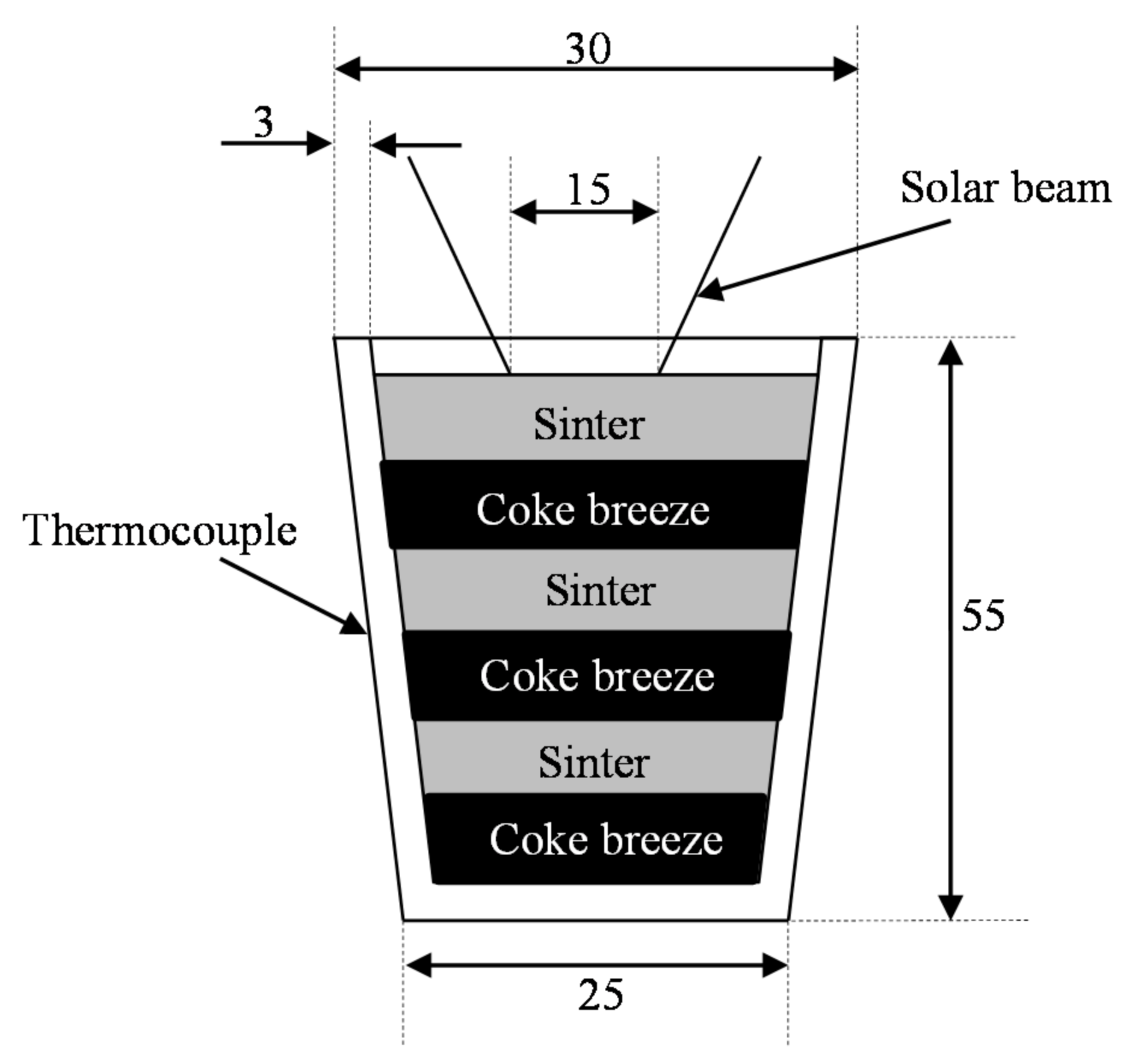
Experiments were performed in a 1.5 kW vertical axis solar furnace located in Odeillo (France) (the same as in previous experiments). Mixtures were loaded in tabular alumina crucibles (55 mm height, 30 mm upper diameter, 25 mm lower diameter, and 3 mm in thickness) that were located below the focal point (approximately 15 mm in diameter) (see Figure 18). The experiments lasted approximately 15 min, although the variable weather conditions (cloudy day) in this set of experiments led to several stop-restart cycles. The samples were held below the focal point during all the experiments and were air-cooled after removing the solar energy beam. Tests were performed under air atmosphere. However, a glass hood connected to a pump was used to catch gases and particles released during the experiments, which otherwise could become adhered to the parabolic concentrator. The same materials were used in the five experiments, with the purpose of reproducibility. As previously indicated, coke and sinter were loaded into the crucibles in alternative layers, with the purpose of promoting reductant conditions during the solar experiments (Figure 18). The crucibles that were used in the experiments were the same ones that were used in the sintering process, with the exception of the crucible used in the sample BF1, which was bigger to check the maximum diameter of the zone affected by the heat (approximately 25 mm in diameter). The chemical composition of the sinter (Voestalpine sintered, fine granulometric fraction) determined by using X-ray fluorescence is collected in Table 11, while the chemical composition of the coke breeze is shown in Table 2.
In Table 12, we see the masses of each layer of sinter and coke, as well as the initial and final masses (total) and the mass losses. We see that mass losses are all in the same order of magnitude. They are a bit higher in the case of BF1, which is because a bigger crucible was used (the surface of the open face is twice that of the conventional crucibles) and projections of material are, consequently, higher. What happened in the process described in Section 2 happened here, too: The upper layer was melted during the experiments. The presence of liquid phase fills the empty spaces and the reduction in lower layers is blocked, as a crust is formed and oxygen is not available to burn part of the carbon. If CO2 is not available, the Boudouard mechanism is not satisfied and the reduction of the iron ore can only progress through the direct reduction mechanism, and this direct reduction mechanism involves low conversions [29]. If the reaction is almost totally blocked at the depth of 12–20 mm from the surface (from the depth of 12–20 mm to the bottom of the crucible, there is not reaction) the material below this point remains unreacted. This way, the option of a moving system (as in Section 3.2) and using only two layers (sinter in the upper one and coke breeze in the other) could have been more productive.
Experimental conditions are displayed in Table 13. BF2, BF3, and BF5 were treated for equivalent times. The reason is that the day the experiments were conducted was characterized by an abundant number of clouds that obliged us to stop and restart the experiments, although they were held below the focal point for equivalent times.

3.3.2. Results and Discussion

A total of five samples were obtained in this group of experiments. Four samples were analyzed using the X-ray diffraction technique (conditions were described in Section 2) to identify the phases that were obtained during the experiments; see Figure 19, Figure 20, Figure 21 and Figure 22. Sample BF4 was not analyzed due to the experimental conditions (less than 5 min at the level of radiation used in other experiments, and the results could not be comparable).
The chemical composition of the crystalline phases in the samples discounting the presence of the amorphous is shown in Table 14. The software XPowder12 Ver. 01.02 was used to perform the quantitative analysis of the crystalline phases. Samples for X-ray diffraction analyses were taken from the reacted volume (12–20 mm in depth and 20–25 mm in diameter), because the rest of the material did not react during the experiments.
Iron was identified in three of the samples that were analyzed, although the quantities were significantly lower than those initially expected according to the quantities of coke that were added. The presence of magnetite was expected, as its presence is thermodynamically favorable under the conditions reached during experiments with concentrated solar energy. The presence of wüstite as main phase is indicative of the fact that the initial hematite was reduced during the experiments. The reduction of the Fe2O3 to FeO is faster than that of FeO to Fe, as described by Fruehan [30]. This explains the quantity of wüstite and the smaller amount of metallic iron. Same as in the experiments described in Section 3.2, the absence of a reducing atmosphere (that could be obtained by using a gas flow) impeded the full conversion of iron sinter into a kind of pig iron (like the pig iron that could be used in the production of cast irons [31]). The utilization of a glass hood connected to a pump suctioned the air and trapped the reductant gases and limited the Boudouard mechanism. In several cases, γ-Fe2O3 was identified, which has a structure like that of magnetite (Fe(II)-deficient magnetite that is also ferromagnetic—the same as the magnetite—and this explains the behavior of the sample when using a magnet), formed by oxidation of the magnetite.
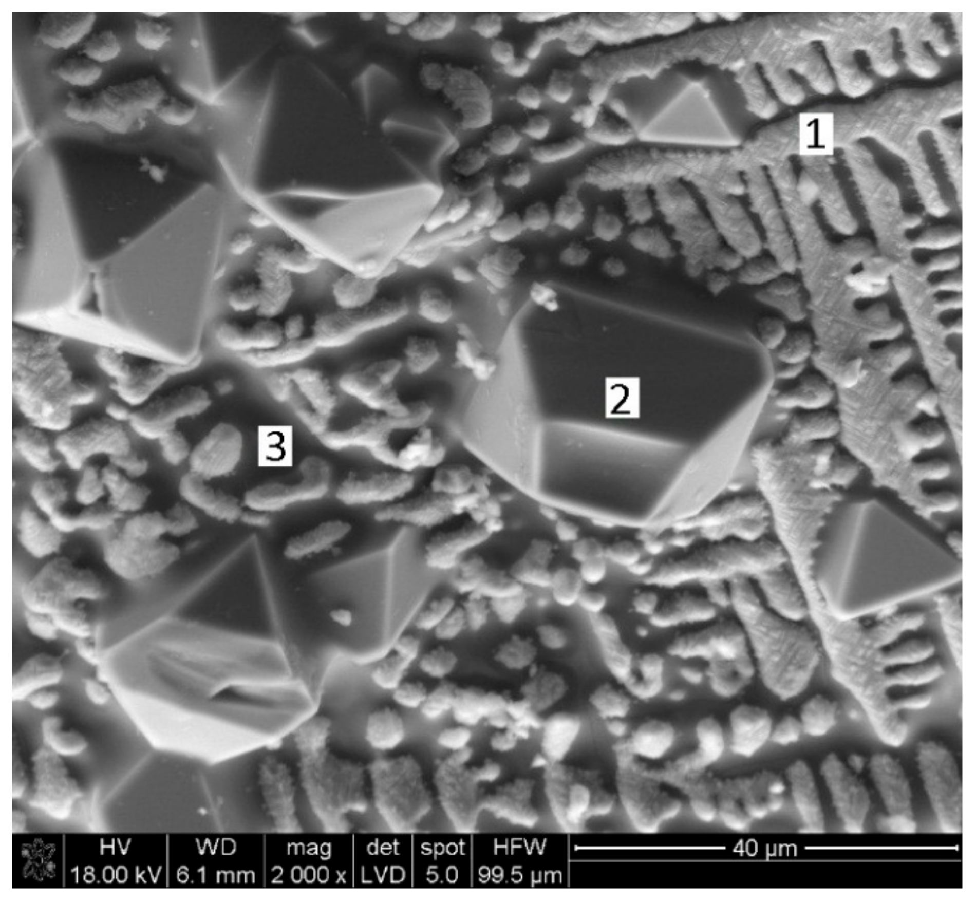
Samples were also observed using SEM-EDX equipment, which allowed us to perform point analyses. Samples were taken from the zone of reaction. See Figure 23 and Table 15.
Points 1 and 3 represent the iron rich phase obtained via solar; the presence of Mg, Al, Si, and Ca could indicate drags of slag. Regarding Point 2, it might belong to Fe3O4 (we see the typical structure of the magnetite), but with significant quantities of aluminum (maybe as oxide). With lower magnification we see in Figure 24 the aspect of the sample BF1, where we see that the zones with shape similar to Points 1 and 3 occupy most of the image.
The disposition of the sinter and the coke breeze in alternative layers, where the layer in contact with the solar beam is that of sinter, allows to have suitable conditions for the process. Concentrated solar energy melted part of the sinter upper layer. A crust of melted material impeded the circulation of the gas, although coke is burnt in the lower layer and the Boudouard mechanism is verified in the presence of solid coke. Carbon monoxide is formed, and the sinter is reduced in the upper layer. Significant quantities of wüstite and metallic iron, are detected. This indicates that the sinter was partially reduced. Same as in the case described in Section 3.2, the utilization of a reductant atmosphere could have increased the quantity of metallic iron. Magnetite and maghemite could have been obtained due to the contact of the surface with the air atmosphere (oxidation of the wüstite). Unfortunately, the reduction was not extended to all the volume of material available in the crucible. In this way, further studies should be carried out to increase the amount of metallic iron obtained. Even the disposition of the material in two single layers (lower of coke and upper of sinter) with movement below the solar beam (as in Section 3.2) could increase the reduction of the sinter, or at least help to avoid the presence of significant quantities of unreacted material in the crucible.

3.4. Potential Advantages of Solar Energy: Reduction in Both CO2 Emissions and Costs

Different methods based on the direct reduction of the ferric load have been studied in the last few decades as an alternative to the production of steel in the blast furnace (smelting reduction), some of them based on the direct reduction with gas (some researchers that sign this paper have studied the direct reduction of hematite to obtain magnetite in a fluidized bed solar furnace [5]) and others based on the smelting reduction (as that described in this paper). Despite the significant number of alternative processes, approximately 72% of steel is currently produced through the blast furnace and converter route. The process described in this paper is based on smelting reduction, where coke is used as a reductant and concentrated solar energy is used to supply heat to the process. Basic research is provided in this paper, so further development should be carried out to scale up the process to the industrial level. However, in the following lines, we will provide the potential advantages of the solar process if compared with the traditional route and the preliminary requirements of the process.
Approximately 450 kg of carbon (coke and pulverized coal) are required to produce 1 ton of steel [14]. This carbon is used with three purposes in the blast furnace (as previously indicated in the text): 30–45% of the carbon is used to produce heat (to favor the reactions and keep in molten state the metal and the slag in the lower part of the furnace), 10–15% of coke is used to support the load in a reductant environment (the coke must resist the burden at high temperature under a reducing environment (apart from having a suitable porosity for the circulation of the gases)), and 40–60% of the carbon is used to reduce the iron ore (the coke reacts with the CO2 to produce CO, which reduces the burden, according to the Boudouard mechanism [32]). This means that only 180–270 kg of the coke is used to reduce the load and produce 1 ton of steel. In the process described in this paper, coke was only used to reduce the load and the heat is provided by the concentrated solar energy (the costs of this energy would be limited to the installation/amortization costs). Considering the current coke price, 200–250 €/ton coke, and taking into account that only 180–270 kg of coke would be required to produce 1 ton of steel in the solar process, the coke cost in the solar based process would be in the range 36–68 €/ton steel (BF and converter route, 90–113 €/ton steel), and the potential reduction of costs is in the range 45–54 €/ton steel. Similar calculations could be made in the case of the reduction of CO2 emissions (approximately 1.5–1.8 tons of CO2/ton steel are produced in the case of the BF and converter route [33]), while in the concentrated solar energy process, coke/carbon is only used to reduce the load and CO2 emissions could be reduced to 660–990 kg of CO2/ton steel. This means that CO2 emissions could be reduced by approximately 40–50%, and this would have a positive environmental impact, but also mean a reduction in the production cost, as CO2 emission taxes would be significantly reduced (the cost of emitting CO2 is 22.5 €/ton CO2 with a growing trend, according to the EU Emissions Trading System). The potential reduction in both CO2 and coke consumption (and thus costs) could justify the potential research/application of concentrated solar energy in ironmaking, although it is true that further development should be done to scale up the process.
In general lines, the design of the solar furnace would require a reductant atmosphere (CO or CO2) to avoid reoxidation of the obtained iron in the presence of ambient atmosphere, or at least working in a closed environment (avoiding oxidizing the air environment). Temperatures were sufficiently high (>1500 °C) to achieve the smelting reduction of the load, but also to achieve the separation of the metal and slag. A continuous system that passed below the focal point could solve the problem of the treated depth, although using solar furnaces with more power could allow to treat significant quantities of material (later, we indicate the solar processes developed to a demonstration scale, where they indicate that quantities of tons daily could be produced). Not a single solar process linked to materials was developed to industrial scale, but many processes were studied using concentrated solar energy [3]. In this way, only two processes were studied for the scalation up to industrial level [3]: The production of lime in a solar furnace, and the utilization of solar energy in the ZnO/Zn couple to store energy. In the case of the solar lime, Meier et al. [34,35,36,37] designed a kiln furnace heated indirectly by means of a system of rotatory tubes, and they concluded that the process could be used to produce high quality lime, as the solar lime price would be twice the price of the conventional lime. In the case of the zinc (zinc can be used in water splitting to produce H2, or to use zinc as combustible in batteries and combustible cell), several research projects have allowed to build (EU-SOL-ZINC, 0.3 MW solar plants for the production of 50 kg Zn/h, [38]) and design several demonstration plants (for instance, a 5 MW conceptual design of demonstration plant, 1700 kg Zn/h; and, other of 30 MW to produce 10,000 kg Zn/h [39]). These two research lines allows us to think that if the process is deeply studied, concentrated solar energy could be used in the production of steel (as significant quantities of steel could be produced every day), and this process could be used in countries with abundance of solar energy, as costs could be reduced and the environmental impact could be minimized (as indicated). The potential reduction in CO2 emissions, coke consumption, and costs could justify the research in the utilization of concentrated solar energy in ironmaking.

4. Conclusions

Solar energy, when adequately concentrated, could be a source of energy to be used in thermal applications. In this way, carbon dioxide emissions could be significantly reduced.
In this paper, we have proposed the utilization of concentrated solar energy in ironmaking. We have studied the two processes used in this industry:
Iron ore agglomeration: Industrial iron ore mixture and coke breeze were used as raw materials. The reduction of CO2 emissions in the case of the iron ore sintering could be achieved through two routes: Replacing the initializing system, although this would have a limited impact in the reduction of carbon dioxide emissions; and/or reducing/eliminating the coke mixed with the sinter. Experiments performed have shown that the temperatures were so high that the mixture was melted in the upper face, and in this way, the reaction was blocked in a depth of approximately 12–15 mm. Moreover, the lack of a downdraught system impeded the circulation of the gases through the load and, in this way, the progress of the process until the bottom of the crucible. The lack of gas flow also explains the presence of important quantities of wüstite, as it would be oxidized in the presence of air. Reducing/eliminating the coke mixed with the sinter could be achieved by replacing coke with solar energy, but this seems difficult, taking into account that concentrated solar energy is a punctual heat source. The application of concentrated solar energy seems to have limited utility in the sintering process.
Reduction of iron oxides: Laboratory quality iron oxide (III) and carbon, and industrial iron ore sinter and coke breeze were used as raw materials. The decrease of the carbon dioxide emissions in the reduction of the iron ore with carbonaceous material can be achieved by replacing the part of the coke used to supply heat to the process with solar energy, as coke used to reduce the charge cannot be eliminated. In this way, the carbon dioxide emissions could be significantly reduced. Both iron oxide (III) and carbon and iron ore sinter and coke breeze mixtures were partially reduced, as magnetite and wüstite were detected in all samples, and metallic iron was detected in several samples. The utilization of air atmosphere makes that part of the carbon monoxide pass to the atmosphere without reducing the charge (the formation of carbon monoxide through the Boudouard mechanism is the controlling step). If a reductant or CO2 atmosphere was used, the conversion of the iron oxide (III) into iron would have been higher. The disposition of the sinter and coke in alternative layers when using real materials increased the amount of metallic iron in the final samples, but reduced products were only found in the upper sinter layer. A moving system with two layers (sinter above, coke below) could have given better results.
Concentrated solar energy could be an alternative in metallurgical processes. The utilization of this energy source in ironmaking was shown in this paper. Interesting results were obtained, especially in the reduction of iron oxides. However, further studies should be carried out to consider solar energy-based processes as an alternative to the well-studied conventional processes.

Author Contributions

D.F.-G. and L.F.V.G. designed the experiments; D.F.-G., I.R.-B., and C.G.-G. performed the experiments; D.F.-G. and J.P. analyzed the results; D.F.-G. and L.F.V.G. interpreted the results; D.F.-G. and J.P.-N. wrote the manuscript.

Funding

Financial support by the Access to Research Infrastructures activity in the 7th Framework Program of the EU (SFERA 2 Grant Agreement No. 312643) is gratefully acknowledged and the use of the facilities and its researchers/technology experts. This research was supported by the Spanish Ministry of Education, Culture, and Sports via an FPU (Formación del Profesorado Universitario) grant to Daniel Fernández González (FPU014/02436).

Conflicts of Interest

The authors declare no conflict of interest.

References

  1. World Steel Association: World Steel in Figures. 2018. Available online: https://www.worldsteel.org/publications/bookshop/product-details.~World-Steel-in-Figures-2018~PRODUCT~World-Steel-in-Figures-2018~.html (accessed on 24 October 2018).
  2. Fernández-González, D.; Ruiz-Bustinza, I.; Mochón, J.; González-Gasca, C.; Verdeja, L.F. Iron Ore Sintering: Raw Materials and Granulation. Miner. Process. Extr. Metall. Rev. 2017, 38, 36–46. [Google Scholar] [CrossRef]
  3. Fernández-González, D.; Ruiz-Bustinza, I.; González-Gasca, C.; Piñuela-Noval, J.; Mochón-Castaños, J.; Sancho-Gorostiaga, J.; Verdeja, L.F. Concentrated solar energy applications in materials science and metallurgy. Sol. Energy 2018, 170, 520–540. [Google Scholar] [CrossRef]
  4. Fernández-González, D.; Prazuch, J.; Ruiz-Bustinza, I.; González-Gasca, C.; Piñuela-Noval, J.; Verdeja, L.F. Solar synthesis of calcium aluminates. Sol. Energy 2018, 171, 658–666. [Google Scholar] [CrossRef]
  5. Ruiz-Bustinza, I.; Cañadas, I.; Rodríguez, J.; Mochón, J.; Verdeja, L.F.; García-Carcedo, F.; Vázquez, A. Magnetite Production from Steel Wastes with Concentrated Solar Energy. Steel Res. Int. 2013, 84, 207–217. [Google Scholar] [CrossRef]
  6. Sibieude, F.; Ducarroir, M.; Tofighi, A.; Ambriz, J. High temperature experiments with a solar furnace: The decomposition of Fe3O4, Mn3O4, CdO. Int. J. Hydrogen Energy 1982, 7, 79–88. [Google Scholar] [CrossRef]
  7. Steinfeld, A.; Fletcher, E.A. Theoretical and experimental investigation of the carbothermic reduction of Fe2O3 using solar energy. Energy 1991, 16, 1011–1019. [Google Scholar] [CrossRef]
  8. Steinfeld, A.; Kuhn, P.; Karni, J. High-temperature solar thermochemistry: Production of iron and synthesis gas by Fe3O4-reduction with methane. Energy 1993, 18, 239–249. [Google Scholar] [CrossRef]
  9. Mochón, J.; Ruiz-Bustinza, I.; Vázquez, A.; Fernández, D.; Ayala, J.M.; Barbés, M.F.; Verdeja, L.F. Transformations in the Iron-Manganese-Oxygen-Carbon System Resulted from Treatment of Solar Energy with High Concentration. Steel Res. Int. 2014, 85, 1469–1476. [Google Scholar] [CrossRef]
  10. Pardo, N.; Moya, J.A. Prospective scenarios on energy efficiency and CO2 emissions in the European iron & steel industry. Energy 2013, 54, 113–128. [Google Scholar]
  11. Wang, K.; Wang, C.; Lu, X.; Chen, J. Scenario analysis on CO2 emissions reduction potential in China’s iron and steel industry. Energy Policy 2007, 35, 2320–2335. [Google Scholar] [CrossRef]
  12. Ariyama, T.; Sato, M. Optimization of ironmaking process for reducing CO2 emissions in the integrated steel works. ISIJ Int. 2006, 46, 1736–1744. [Google Scholar] [CrossRef]
  13. Naito, M.; Takeda, K.; Matsui, Y. Ironmaking technology for the last 100 years: Deployment to advanced technologies form introduction of technological know-how, and evolution next-generation process. ISIJ Int. 2015, 55, 7–35. [Google Scholar] [CrossRef]
  14. Bertlin, H. Review coal and coke for blast furnaces. ISIJ Int. 1999, 39, 617–624. [Google Scholar] [CrossRef]
  15. Kirschena, M.; Badr, K.; Pfeifer, H. Influence of direct reduced iron on the energy balance of the electric arc furnace in steel industry. Energy 2011, 36, 6146–6155. [Google Scholar] [CrossRef]
  16. Pardo, N.; Moya, J.A.; Vatopoulos. Prospective Scenarios on Energy Efficiency and CO2 Emissions in the EU Iron and Steel Industry; European Commission, Joint Research Centre, Institute for Energy and Transport: Petten, The Netherlands, 2012; ISBN 978-92-79-54191-9. [Google Scholar]
  17. Eisele, T.C.; Kawatra, S.K. A review of binders in iron ore pelletization. Miner. Process. Extr. Metall. Rev. 2003, 24, 1–90. [Google Scholar] [CrossRef]
  18. Fernández-González, D.; Martín-Duarte, R.; Ruiz-Bustinza, I.; Mochón, J.; González-Gasca, C.; Verdeja, L.F. Optimization of sinter plant operating conditions using advanced multivariate statistics: Intelligent data processing. JOM 2016, 68, 2089–2095. [Google Scholar] [CrossRef]
  19. Fernández-González, D.; Ruiz-Bustinza, I.; Mochón, J.; González-Gasca, C.; Verdeja, L.F. Iron Ore Sintering: Process. Miner. Process. Extr. Metall. Rev. 2017, 38, 215–227. [Google Scholar] [CrossRef]
  20. Fernández-González, D.; Ruiz-Bustinza, I.; Mochón, J.; González-Gasca, C.; Verdeja, L.F. Iron Ore Sintering: Quality Indices. Miner. Process. Extr. Metall. Rev. 2017, 38, 254–264. [Google Scholar] [CrossRef]
  21. Fernández-González, D.; Ruiz-Bustinza, I.; Mochón, J.; González-Gasca, C.; Verdeja, L.F. Iron Ore Sintering: Environment, Automatic and Control Techniques. Miner. Process. Extr. Metall. Rev. 2017, 38, 238–249. [Google Scholar] [CrossRef]
  22. Fernández-González, D.; Piñuela-Noval, J.; Verdeja, L.F. Iron Ore Agglomeration Technologies. In Iron Ores and Iron Oxide Materials, 1st ed.; Shatokha, V., Ed.; Intech Open: London, UK, 2018; pp. 61–80. ISBN 978-1-78923-320-9. [Google Scholar]
  23. Ghosh, A.; Chatterjee, A. Ironmaking and Steelmaking; PHI Learning Private Limited: New Dehli, India, 2008; ISBN 978-8120332898. [Google Scholar]
  24. Hayashi, N.; Komarov, S.; Kasai, E. Heat transfer analysis of the mosaic embedding iron ore sintering (MEBIOS) process. ISIJ Int. 2009, 49, 681–686. [Google Scholar] [CrossRef]
  25. Lu, L.; Ishiyama, O. Iron ore sintering. In Iron Ore. Minaralogy, Processing and Environmental Sustainability; Wordhead Publishing; Elsevier: Cambridge, UK, 2015; pp. 395–429. ISBN 978-1-78242-159-7. [Google Scholar]
  26. Webster, N.A.S.; Pownceby, M.I.; Madsen, I.C.; Kimpton, J.A. Silico-ferrite of calcium and aluminium (SFCA) iron ore sinter bonding phases: new insights into their formation during heating and cooling. Metall. Mater. Trans. B 2012, 43B, 1344–1357. [Google Scholar] [CrossRef]
  27. Ballester, A.; Sancho, J.; Verdeja, L.F. Metalurgia Extractiva. Volumen I. Fundamentos; Síntesis: Madrid, Spain, 2003; ISBN 84-7738-802-4. [Google Scholar]
  28. Sancho, J.; Verdeja, L.F.; Ballester, A. Metalurgia Extractiva. Volumen II. Procesos de Obtención; Síntesis: Madrid, Spain, 2000; ISBN 84-7738-803-2. [Google Scholar]
  29. Rao, Y.K. The kinetics of reduction of hematite by carbon. Metall. Trans. 1971, 2, 1439–1447. [Google Scholar]
  30. Fruehan, R.J. The rate of reduction of iron oxides by carbon. Metall. Trans. B 1977, 8, 279–286. [Google Scholar] [CrossRef]
  31. Pero-Sanz, J.P.; Fernández-González, D.; Verdeja, L.F. Physical Metallergy of Cast Irons; Springer: Cham, Switzerland, 2018; ISBN 978-3-319-97312-8. [Google Scholar]
  32. Geerdes, M.; Chaigneau, R.; Kurunov, I.; Lingiardi, O.; Ricketts, J. Modern Blast Furnace Ironmaking an Introduction, 3rd ed.; IOS Press: Amsterdam, The Netherlands, 2015; p. 116. ISBN 978-1-61499-499-2. [Google Scholar]
  33. Kundak, M.; Lazic, L.; Crnko, J. CO2 emissions in the steel industry. Metalurgija 2009, 3, 193–197. [Google Scholar]
  34. Meier, A.; Bonaldi, E.; Cella, G.M.; Lipinski, W.; Wuillemin, D.; Palumbo, R. Design and experimental investigation of a horizontal rotary reactor for the solar thermal production of lime. Energy 2004, 29, 811–821. [Google Scholar] [CrossRef]
  35. Meier, A.; Bonaldi, E.; Cella, G.M.; Lipinski, W. Multitube rotary kiln for the industrial solar production of lime. J. Sol. Energy Eng. 2005, 127, 386–395. [Google Scholar] [CrossRef]
  36. Meier, A.; Gremaud, N.; Steinfeld, A. Economic evaluation of the industrial solar production of lime. Energy Convers. Manag. 2005, 46, 905–926. [Google Scholar]
  37. Meier, A.; Bonaldi, E.; Cella, G.M.; Lipinski, W.; Wuillmin, D. Solar chemical reactor technology for industrial production of lime. Sol. Energy 2006, 80, 1355–1362. [Google Scholar] [CrossRef]
  38. Wieckert, C.; Frommherz, U.; Kräupl, S.; Guillot, E.; Olalde, G.; Epstein, M.; Santén, S.; Osinga, T.; Steinfeld, A. A 300 kW solar chemical pilot plant for the carbothermic production of zinc. J. Sol. Energy Eng. 2006, 129, 190–196. [Google Scholar] [CrossRef]
  39. Epstein, M.; Olalde, G.; Santén, S.; Steinfeld, A.; Wieckert, C. Towards the industrial solar carbothermal production of zinc. J. Sol. Energy Eng. 2008, 130, 014505. [Google Scholar] [CrossRef]
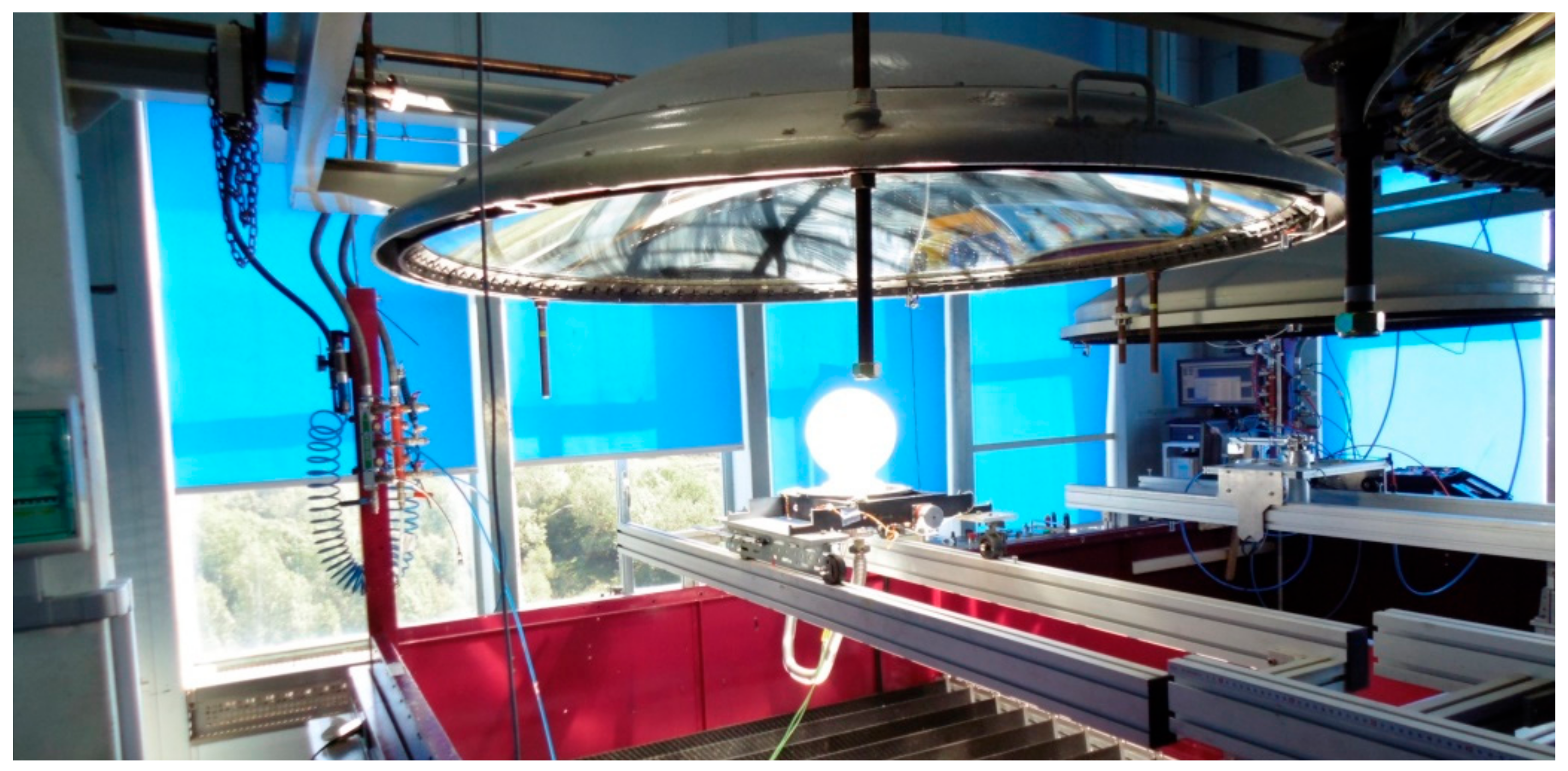
Figure 1. Scheme of the parabolic concentrator.
Metals 08 00873 g001
Figure 2. (a) Scheme of the experimental device used in the tests, distances in millimeters; (b) image of the real conditions, with fumes being released from the sample (thermocouple wire in black, located at an average height of the crucible).
Metals 08 00873 g002
Figure 3. X-ray diffraction pattern of the sample Sint1.
Metals 08 00873 g003
Figure 4. X-ray diffraction pattern of the sample Sint2.
Metals 08 00873 g004
Figure 5. X-ray diffraction pattern of the sample Sint3.
Metals 08 00873 g005
Figure 6. X-ray diffraction pattern of the sample Sint4.
Metals 08 00873 g006
Figure 7. X-ray diffraction pattern of the sample Sint5.
Metals 08 00873 g007
Figure 8. SEM-EDX for the sample Sint4.
Metals 08 00873 g008
Figure 9. SEM image for the sample Sint4 at lower magnification.
Metals 08 00873 g009
Figure 10. (a) Image of the crucible used in the experiments, distances in millimeters. Position of the thermocouples: T1 located inside of the crucible, T2, T3, and T4 located outside at the bottom of the crucible; (b) measurements of the thermocouples for a sample treated with concentrated solar energy.
Metals 08 00873 g010
Figure 11. Samples loaded into the crucibles.
Metals 08 00873 g011
Figure 12. X-ray diffraction diagram for the sample E20P1.
Metals 08 00873 g012
Figure 13. X-ray diffraction diagram for the sample E20P2.
Metals 08 00873 g013
Figure 14. X-ray diffraction diagram for the sample E20P3.
Metals 08 00873 g014
Figure 15. X-ray diffraction diagram for the sample E20P4.
Metals 08 00873 g015
Figure 16. Sample once treated with concentrated solar energy (E20P1).
Metals 08 00873 g016
Figure 17. SEM-EDX for the sample E25P2.
Metals 08 00873 g017
Figure 18. Scheme of the device used in the experiments, distances in millimeters.
Metals 08 00873 g018
Figure 19. X-ray diffraction pattern for the sample BF1.
Metals 08 00873 g019
Figure 20. X-ray diffraction pattern for the sample BF2.
Metals 08 00873 g020
Figure 21. X-ray diffraction pattern for the sample BF3.
Metals 08 00873 g021
Figure 22. X-ray diffraction pattern for the sample BF5.
Metals 08 00873 g022
Figure 23. SEM-EDX image (BF1).
Metals 08 00873 g023
Figure 24. Sample BF1 with lower magnification.
Metals 08 00873 g024
Table 1. Chemical composition of the Voestalpine sinter feed.
PhaseContent (mass %)
Fe2O364.09
CaO10.20
C7.47
SiO28.64
Al2O33.57
MgO2.87
MnO1.99
K2O0.53
SO30.22
Na2O0.13
P2O50.11
TiO20.10
Cl472 ppm
Cr2O3127 ppm
CuO-
CaO/SiO21.18
Table 2. Chemical composition of the coke breeze.
PhaseContent (mass %)
H2O17.19
Fe Total1.18
FeO0.00
Fe2O31.70
CaO0.71
SiO26.58
Al2O33.23
MgO0.19
Celemental83.84
H2Ocrystallization (chemically bonded)1.92
Balance1.83
Table 3. Experimental conditions for the iron ore agglomeration.
SampleTime (min)Initial Mass (g)Final Mass (g)Mass Loss (%)Average Incident Radiation (W/m2)
Sint1Nondetermined22.716.925.6564
Sint2122116.621.0848
Sint3152216.823.6917
Sint4122317.922.2881
Sint52022.718.120.3887
Table 4. Application of the power in each sample (SO, shutter opening (%); T, time (min); P, power (W)).
SampleSO1T1P1SO2T2P2SO3T3P3SO4T4P4
Sint160Nondetermined472---------
Sint2510–3649643–12814------
Sint3250–1344451–5619605–15825---
Sint4250–1330451–5595705–12925---
Sint5250–1333401–5532705–16.59319016.5–201197
Table 5. Quantitative analysis of the phases available in the sample discounting amorphous phases.
PhaseSint1Sint2Sint3Sint4Sint5
FeO56.40 ± 0.748.90 ± 0.710.40 ± 1.957.30 ± 1.255.30 ± 1.1
CaFeSiO41.60 ± 1.607.30 ± 2.342.60 ± 0.88.30 ± 3.7-
MgFe2O415.10 ± 1.621.60 ± 1.7-18.00 ± 3.2-
Fe3O422.00 ± 1.422.10 ± 1.747.00 ± 0.616.40 ± 3.315.10 ± 3.1
MnAl2O4----26.60 ± 2.3
Table 6. Point analysis for the sample Sint4.
ElementPoint 1Point 2
Carbon (wt. %)1.752.39
Oxygen (wt. %)23.2236.13
Magnesium (wt. %)0.982.46
Aluminum (wt. %)0.675.29
Silicon (wt. %)0.7814.55
Phosphorus (wt. %)-1.13
Sulphur (wt. %)0.40-
Potassium (wt. %)0.341.64
Calcium (wt. %)1.039.58
Manganese (wt. %)1.592.59
Iron (wt. %)69.2424.25
Table 7. Experimental conditions.
SampleCarbon Excess (%)Initial Mass (g)Final Mass (g)Mass Loss (%)
E20 P1252.0273--
E20 P2251.5173--
E20 P3252.0484--
E20 P4251.9949--
E21 P1401.6758--
E21 P2401.9317--
E21 P3401.3882--
E25 P1401.09840.884419.48
E25 P2401.85091.477120.19
E31 P1401.68301.402716.65
E32 P1100.5147--
E33 P1101.69561.455814.14
E33 P2101.50921.291814.40
E34 P2251.48141.208318.43
E35 P2401.48011.207018.45
Table 8. Experimental conditions (continuation).
SampleSpeed (mm/s)Incident Radiation (W/m2)Shutter Opening (%)Power (W)Tmax (°C)
E20 P10.7692760.18391367
E20 P20.6094151.47261353
E20 P30.5095551.17321337
E20 P40.30968507261338
E21 P10.2597950.67431309
E21 P20.2599550.6755-
E21 P30.2594660854-
E25 P10.25101069.510531328
E25 P20.25102869.410731309
E31 P10.2595770.110061266
E32 P10.25885709291084
E33 P10.2592470.99831191
E33 P20.259457510631232
E34 P20.259618011531306
E35 P20.2595979.811481266
Table 9. Quantities of each phase in the final sample.
SampleFe2O3 (%)Fe3O4 (%)FeO (%)Fe (%)Al6Si2O13 (%)
E20 P1-37.0 ± 1.459.5 ± 0.73.50 ± 2.4-
E20 P231.50 ± 0.647.60 ± 1.215.30 ± 1.85.60 ± 2.0-
E20 P329.40 ± 0.647.30 ± 1.018.60 ± 1.64.80 ± 1.8-
E20 P412.70 ± 1.063.70 ± 0.520.20 ± 1.23.30 ± 1.5-
E21 P128.60 ± 0.660.90 ± 0.910.50 ± 2.0--
E21 P218.40 ± 1.063.10 ± 0.618.60 ± 1.5--
E21 P3(no reaction)--
E25 P19.6 ± 2.264.1 ± 0.79.7 ± 2.2-16.6 ± 1.9
E25 P22.10 ± 0.493.40 ± 0.2--4.50 ± 0.7
E31 P15.2 ± 1.079.8 ± 0.314.9 ± 0.9--
E32 P163.6 ± 0.336.4 ± 0.6---
E33 P112.20 ± 1.181.20 ± 0.46.60 ± 1.3--
E33 P25.90 ± 2.789.10 ± 0.8--5.90 ± 2.8
E34 P2-93.80 ± 0.5--6.20 ± 1.6
E35 P213.20 ± 1.512.10 ± 1.96.90 ± 2.0-67.80 ± 0.6
Table 10. Point analysis for the sample E25P2.
ElementPoint 1Point 2Point 3Point 4Point 5
Oxygen (wt. %)8.9017.4019.0328.6734.28
Aluminum (wt. %)3.4412.4313.4218.1123.87
Silicon (wt. %)5.530.6339.4035.7337.30
Potassium (wt. %)0.540.423.582.553.26
Iron (wt. %)81.5969.1324.5814.941.29
Table 11. Chemical composition of the iron ore sinter (Voestalpine sintered) determined using X-ray fluorescence.
PhaseContent
Fe2O369.10%
CaO10.84%
SiO212.50%
Al2O32.87%
MgO2.60%
MnO0.47%
K2O0.96%
Na2O0.50%
P2O50.04%
TiO20.07%
CaO/SiO20.87
Table 12. Masses of reagents involved in the experiments (CL, mass of the Coke Layer in grams; SL, mass of the Sinter Layer in grams).
SampleCL1SL1CL2SL2CL3SL3CL4SL4CL5SL5Initial Mass (g)Final Mass (g)Mass Loss (%)
BF11.63.31.731.73.23.23.74.915.842.133.819.7
BF22.53.22.82.63.22.9----17.214.814.0
BF32.53.22.92.73.43.2----17.915.115.6
BF42.73.2333.33.6----18.816.213.8
BF53.33.62.93.23.14----20.117.612.4
Table 13. Experimental conditions.
SampleTime (min)Incident Radiation (W/m2)Shutter Opening
BF1≃15variable (average 933)50–82
BF21597651
BF31590250
BF4(less than 5 min at >876 W/m2)87650
BF52088320–60
Table 14. Chemical analysis of the samples discounting the presence of amorphous phases.
PhaseBF1BF2BF3BF5
FeO74.60 ± 0.853.60 ± 0.833.50 ± 1.046.40 ± 0.9
γ-Fe2O36.30 ± 2.7-15.00 ± 2.09.20 ± 2.7
Mg(Fe3+)2O49.40 ± 2.6-19.80 ± 1.88.80 ± 2.8
Fe3O49.80 ± 2.613.80 ± 2.217.60 ± 1.818.60 ± 2.3
CaFe2+SiO4-2.90 ± 2.66.90 ± 2.84.10 ± 3.1
SiO2---6.10 ± 2.0
Fe-29.70 ± 1.74.50 ± 3.06.90 ± 3.0
Table 15. Results of the point analysis (BF1).
ElementPoint 1Point 2Point 3
Iron (wt. %)84.7936.0581.90
Oxygen (wt. %)6.6725.494.04
Carbon (wt. %) 2.031.05-
Magnesium (wt. %)0.194.380.33
Aluminum (wt. %)1.0126.722.46
Silicon (wt. %)0.290.880.68
Manganese (wt. %)2.371.894.55
Calcium (wt. %)1.081.243.59
Potassium (wt. %)0.400.550.33
Phosphorus (wt. %)0.060.28-
Titanium (wt. %)0.710.801.10
Vanadium (wt. %)0.400.661.02
TOTAL100100100