Abstract
Dissimilar metal joining between titanium and kovar alloys was conducted using electron beam welding. Metallurgical bonding of titanium alloys and kovar alloys was achieved by using a Cu/Nb multi-interlayer. The effects of welding speed on weld appearance, microstructure and mechanical properties of welded joints were investigated. The microstructure of welded joints was characterized by optical microscopy (OM), scanning electron microscopy (SEM), X-ray diffraction (XRD), and energy dispersive spectroscopy (EDS). The mechanical properties of welded joints were investigated by tensile strength and micro-hardness tests. The results showed that welding speed had great effects on the weld appearance, microstructure, and mechanical properties of electron beam-welded joints. With an increase of welding speed, at the titanium alloy side, the amount of (Nb,Ti) solid solution was increased, while the formation of brittle FeTi was effectively suppressed. At the kovar alloy side, microstructure was mainly composed of soft Cu solid solution and some α-Fe + γ phases. In addition, higher welding speeds within a certain range was beneficial for eliminating the formation of cracks, and inhibiting the embrittlement of welded joints. Therefore, the tensile strength of welded joints was increased to about 120 MPa for a welding speed of 10 mm/s. Furthermore, the bonding mechanism of TC4/Nb/Cu/4J29 dissimilar welded joints had been investigated and detailed.
1. Introduction
Kovar alloy is widely applied in the field of electronic industry, which has a coefficient of thermal expansion that is similar to hard (borosilicate) glass [1]. It is acknowledged that titanium alloy has a high specific strength, a high corrosion resistance and is lightweight, and it is commonly used in the nuclear and aerospace industries. There is considerable interest in joining kovar alloys to titanium alloys to meet the needs for nuclear, electronic packaging, and aerospace applications [2,3]. However, it is difficult to bond kovar alloys to titanium alloys because of great differences in their physical and chemical properties. According to the Fe–Ti phase diagram, the brittle intermetallic compounds (IMCs), such as FeTi and Fe2Ti, are easy to form during the welding of titanium alloys and kovar alloys. Chen et al. [4] showed that if CP Ti and 304 stainless steel were bonded by laser welding technology, some brittle IMCs (Fe2Ti and FeTi) easily formed in the weld metal. Similarly, Gao et al. [5] joined titanium and 17-4PH stainless steel by friction stir welding. It was found that a layer-shaped structure formed at the interface, which was composed of FeTi and Fe2Ti. Qin et al. [6] also found that if stainless steel was directly diffusion-bonded to titanium alloy, some brittle IMCs like Fe2Ti and FeTi formed at the interface, which was adverse to the mechanical properties of welded joints. In addition, a FeTi intermetallic compound was produced in the fusion zone during micro-resistance spot welding of a titanium alloy and a 316L stainless steel [7]. Hence, it appears that the challenge in bonding kovar alloys and titanium alloys is the production of the brittle Fe2Ti and FeTi.
For the sake of inhibiting the formation of substantial brittle IMCs, it is beneficial to control the mixing of chemical components by inserting a metallic interlayer. Elrefaey and Tillmann [8] found that the generation of Fe–Ti IMCs could be avoided if titanium and steel were welded by diffusion bonding with a Cu-based interlayer. Similarly, if duplex stainless steel and Ti–6Al–4V alloy were bonded by diffusion welding with a Cu interlayer, Cu–Ti IMCs formed at the interface of the titanium alloy side [9]. The formation of brittle FeTi and Fe2Ti was adverse to the mechanical properties of welded joints. Thus, during the laser welding process of NiTi alloy and stainless steel, Zoeram et al. [10] inserted a Cu interlayer between the substrates for reducing the production of brittle IMCs. The results showed that the Cu–Ti IMCs with a lower hardness than that of Fe–Ti IMCs formed in the fusion zone. Gao et al. [11] studied the laser welding process of a Ti–6Al–4V titanium alloy and an Inconel 718 alloy by using Nb foil as an interlayer. It was found that the Ti–Cr or Ti–Fe IMCs were not observed in the weld metal, indicating that the insertion of a Nb interlayer could effectively inhibit the reaction between the substrates. Zhang et al. [12] investigated the laser welding process of TC4 titanium alloy and 301L stainless steel by inserting a pure Nb interlayer. It was found that if welded joints were obtained by one-pass welding, the Nb interlayer could restrict the reaction between Ti and Fe elements to avoid the production of Fe–Ti IMCs. In addition, it was also found that if titanium alloy was laser welded to NiTi alloy using a Nb interlayer, the solid solution was produced at the titanium alloy side, which was beneficial for the improvement of the properties of welded joints [13].
Technically, it is feasible to bond kovar alloys and titanium alloys using electron beam welding, which possesses several advantages such as precise control of the heating area, high energy density, and a vacuum environment [14]. Consequently, electron beam welding was widely used to bond dissimilar metals [15]. Zhang et al. [16] applied electron beam welding technology to bond a TA15 titanium alloy and a GH600 nickel super-alloy by inserting a Cu foil. It was found that a crack-free welded joint welded by electron beam welding with a Cu foil was acquired. Also, the formation of Ti–Ni IMCs was effectively restrained, which was beneficial for improving the quality of welded joints. If Ti6Al2Mo2V2Zr alloy and 304 stainless steel were bonded by electron beam welding with a Cu filler metal, a crack free welded joint could be acquired [17]. Similarly, if titanium alloy and stainless steel were welded by electron beam welding with a V/Cu multi-interlayer, the formation of brittle Fe–Ti IMCs was effectively inhibited so as to enhance the quality of welded joints [15]. In our previous work, 4J29 kovar alloy (Fe–29Ni–17Co) and TC4 titanium alloy (Ti–6Al–4V) were welded by electron beam welding, which was widely applied in electronic packaging and aerospace industries. Cu/Nb multi-interlayers were used to inhibit the formation of Fe–Ti IMCs to enhance the quality of welded joints and the effects of the thickness of Cu/Nb multi-interlayer on the welded joints’ quality was investigated [18]. However, the quality of welded joints was poor. Therefore, we hope that the quality of welded joints can be enhanced by regulating the other welding parameters. In this work, the effects of welding speed on weld appearance, microstructure, and mechanical properties of welded joints were evaluated. The bonding mechanism of the TC4/Nb/Cu/4J29 dissimilar welded joints was investigated. Our study demonstrated that the regulating of welding speed was effective for inhibiting the formation of brittle Fe–Ti IMCs and improving the quality of welded joints.
2. Experimental Procedure
2.1. Materials and Preparation
The plates of 4J29 kovar alloy (50 × 30 × 2 mm3) and TC4 titanium alloy (50 × 30 × 2 mm3) were used as electron beam welding materials. Their chemical compositions and some physical properties are shown in Table 1 and Table 2 respectively. The metallic interlayer used in this work was a composite of bilayers composed of a pure Nb foil and a pure Cu foil. Before welding, the specimens were ground, polished, washed, and dried in air. A Cu/Nb multi-interlayer was prepared which was a composite of a 0.44 mm-thick pure Cu foil and a 0.38 mm-thick pure Nb foil.

Table 1.
Chemical composition of base metals (wt %).
Table 2.
Physical properties of base metals.
2.2. Welding Method and Processing Parameters
In this work, an electron beam welding machine (PTR EBW 300/5-60 PLC, Werne, Germany) was applied to bond kovar alloys and titanium alloys. As shown in Figure 1, it is a schematic diagram of the dual-pass electron beam welding. First, an electron beam was focused on the interface between kovar alloy and Cu foil and was shifted by 0.1–0.2 mm to the Cu foil side to acquire better welding. Then electron beam was placed in the middle of Nb foil for the second pass. In this study, welding speeds of 6 mm/s, 8 mm/s, and 10 mm/s were performed. The three samples were named as EBW-1 sample, EBW-2 sample, and EBW-3 sample, respectively. The welding parameters are listed in Table 3.
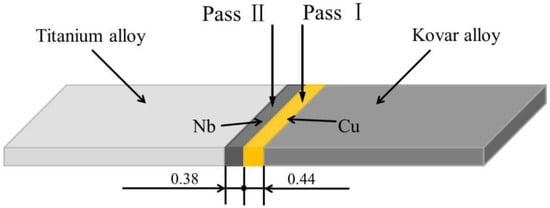
Figure 1.
Schematic experimental conditions of the dual-pass welding procedure.
Table 3.
Welding parameters used in dual-pass welding.
2.3. Analytical Methods
The cross-section of the welds was ground and polished. The weld appearance of welded joints was observed by an optical microscope (OM, Axio Cam MRc5, ZEISS, Wetzlar, Germany). The microstructure of the welded joints was investigated by a scanning electron microscope (SEM, QUANTA FEG 250, Thermo Fisher Scientific, Waltham, MA, USA). Spot and map scan analyses were applied to evaluate distribution of chemical elements by SEM equipped with an X-ray energy-dispersive spectrometer (EDS). The Vickers micro-hardness (HXD-100TM/LCD, TaiMing, Shanghai, China) measurement was performed across the weld metal of the welded joints using a test load of 100 gf and a dwell time of 15 s. A tensile test was performed to evaluate the welded joints’ strength. The specimens were prepared as rectangular bars (45 × 6 × 2 mm3) and the displacement speed was 0.1 mm/min. Finally, the fracture morphology of the welded joints was analyzed by using SEM. Micro-X-ray diffraction (XRD, PANalytical-Empyrean, Almelo, The Netherlands) was conducted on the fracture surface of tensile samples to identify the phase. In this work, the operating voltage was 40 kV, and the operating current was 30 mA with a Cu target. The scanning range was 30–100° (2θ) at a speed of 2°/min.
3. Results and Discussion
3.1. Weld Appearances
Figure 2 shows the cross-section of electron beam-welded joints using a Cu/Nb multi-interlayer at different welding speeds. As can be seen, the increase of welding speed had a significant influence on the situation of fusion. As the welding speed increased, the depth of the weld was increased and the formation of crack was effectively suppressed. In general, a low welding speed can increase the energy input of the weld to increase the depth of the weld. However, in this study, if the welding speed was 6 mm/s, the metal of the Cu side melted rapidly because of the large input of energy, and then the molten metal spread toward Nb side to cover the Nb interlayer. In addition, the heat was absorbed by the flow of molten metal, resulting in the reduction of the melting depth of the Cu side. During second welding, on the side of Nb, energy cannot propagate deeply into the weld due to the covering effect of molten metal, resulting in reduction of the depth of the weld. Large energy input can promote the reaction and diffusion of atoms in weld pool to form brittle IMCs, which is the reason for the embrittlement of welded joints. Meanwhile, the production of thermal stress occurs in weld metal under large amounts of heat input, and cracks begin to form during solidification, as shown in Figure 2a [1]. Wang et al. [15] also found that low welding speed could lead to the formation of crack during the electron beam welding of titanium alloy and stainless steel. If the welding speed was 8 mm/s, although the energy input was decreased, the covering effect of molten metal still existed. Similarly, the crack was also found in the fusion zone, as shown in Figure 2b. If welding speed was increased to 10 mm/s, the depth of the weld was increased and cracks were not found in the weld, as shown in Figure 2c. At a high welding speed, covering effect of molten metal was weakened because of the decrease of energy input. The diffusion of Fe atoms towards the titanium alloy side was inhibited to avoid the formation of a large amount of brittle IMCs. However, at three different welding speeds, a large amount of unmelted Cu and Nb interlayers still remained in the weld, which could become weak places in the weld to lead to low ductility and the low resistance of welded joints. A similar phenomenon was also found in our previous work, which resulted from insufficient heat input [18]. Furthermore, although the melting point of Nb metal is much higher than Cu metal (2468 °C relative to 1084 °C), it was found that the melt volume of Nb metal was slightly less than that of Cu metal. Because the thermal conductivity of Cu metal is about eight times greater than Nb metal, the energy intake from electron beam in Nb metal is more than in Cu metal, resulting in more melting in the Nb metal. At second welding, the electron beam was placed in the middle of the Nb foil, so that the melt volume of Nb metal could be enhanced. In this study, the regulation of welding speed had a limited effect on the improvement of depth of the weld, so that the energy input should be increased by adjusting the size of accelerating voltage or electron beam current to achieve sufficient melting. Also, the focus current also needed to be regulated, which had a significant influence on the weld appearance [19]. Furthermore, macro-segregation features were found by several authors in their work, such as ‘beaches’, ‘peninsulas’, or ‘islands’ [20,21]. In this work, near the unmelted Cu interlayer, some unmixed islands of Cu metal were also observed, as shown in Figure 2. During the process of welding, a layer of unmixed Cu metal in the liquid state can form because of the decrease of complex fluid flow in the vicinity of the weld pool boundary. The unmixed liquid Cu metal is pushed out into the weld pool by the action of convection. The temperature of this area is below its liquidus temperature because of the decrease of liquidus temperature in the weld pool. As a result, the unmixed area can solidify quickly to form some unmixed islands of Cu metal [21].
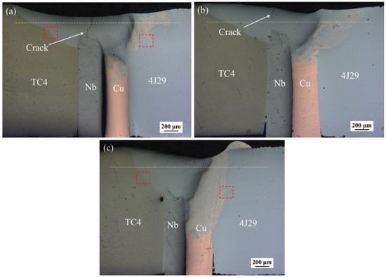
Figure 2.
The cross-section of the weld of welded joints at welding speeds of (a) 6 mm/s (EBW-1), (b) 8 mm/s (EBW-2), and (c) 10 mm/s (EBW-3).
3.2. Microstructure of the Weld Metal of Welded Joints
3.2.1. Microstructure of the Titanium Alloy Side Interface
Since the fusion situation of the welded joint EBW-1 was similar to the welded joint EBW-2, only the microstructures of welded joint EBW-1 and welded joint EBW-3 were studied in this work. For the analysis of microstructure, the analytical areas are marked by red rectangle in Figure 2a,c. In the process of welding, Ti elements are easy to form IMCs with multiple metal elements. For the welded joint EBW-1, Figure 3a shows the microstructure of titanium alloy side made by electron beam welding at a welding speed of 6 mm/s. The microstructure is mainly composed of two phases according to its morphology characteristics; that is, the dark phase (A zone) and white phase (B zone), as labeled with A and B in Figure 3a, respectively. For the welded joint EBW-3 at a welding speed of 10 mm/s, there were also two phases at titanium alloy side. One was a white columnar dendritic phase (C zone), and the other one was a dark intergranular phase (D zone), as shown in Figure 3b. In addition, the dendritic phases mainly form at titanium alloy side. Because the high local undercooling could accelerate the nucleation of grain to form dendritic phase under the high cooling rate [22].
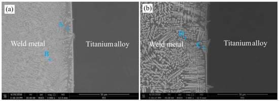
Figure 3.
Microstructure of titanium alloy side interface of welded joints at welding speed of (a) 6 mm/s (EBW-1) and (b) 10 mm/s (EBW-3).
In order to identify phase compositions of titanium alloy side, SEM-EDS was conducted on zones A through D in Figure 3, and the results are given in Table 4. Referring to the relevant phase diagrams (Ti–Nb [23] and Cu–Fe–Ti [24]) and EDS results, certain phases were recognized, as listed in Table 4. It can be deduced that dark phase (A zone) and the white phase (B zone) consisted of FeTi, CuTi2, and (Nb,Ti) solid solutions. Nevertheless, there were certain differences between the two phases, due to their diverse average atom numbers between the A and B zones [25]. Compared with the welded joint EBW-1, the microstructure of the titanium alloy side of the welded joint EBW-3 had a high content of Nb and a low content of Fe, as shown in Table 4. Similarly, it is reckoned that the white columnar dendritic phase (C zone) was composed of CuTi2 and (Nb,Ti) solid solution, while the dark intergranular phase (D zone) consisted of FeTi, CuTi2, and (Nb,Ti) solid solution. In previous study, Ti solid solution and CuTi2 were also found at titanium alloy side, which was beneficial for enhancing the tensile strength of welded joints [18]. Similarly, (Nb,Ti) solid solution was also observed if a NiTiNb alloy and a titanium alloy were bonded by laser welding with a pure Nb filler wire [26]. Consequently, it is proved that a higher welding speed within a certain range can inhibit the reaction of Fe and Ti atoms, thus reducing the formation of FeTi and enhancing the amount of solid solution. Tomashchuk et al. [27] prepared electron beam-welded joints of a titanium alloy and a 316L stainless steel with a Cu interlayer. It was also found that the increase of welding speed could reduce the amount of Fe–TiIMCs.
Table 4.
The main chemical compositions of different zones (at %) at titanium alloy side.
As can be seen from Figure 4 and Figure 5, there are distribution maps of the main elements for the welded joints EBW-1 and EBW-3, respectively. On the basis of the chemical compositions of the weld metal (Table 4), as well as the distribution maps of the main elements in the weld metal of the titanium alloy side (Figure 4 and Figure 5), the amount of Fe and Cu elements in the weld metal of the titanium alloy side was reduced by increasing the welding speed. A reduction of the amount of Fe and Cu atoms could inhibit the reaction between Fe, Cu, and Ti atoms during the process of welding. From the kinetic point of view, the formation of Fe–Ti and Cu–Ti IMCs could be restricted by reducing the reaction between these elements, which was beneficial for reducing the embrittlement of the welded joints [10]. In addition, compared with the welded joint at a welding speed of 6 mm/s, the Nb elements in the weld metal of titanium side tended to concentrate on certain areas to form more solid solution if welding speed is increased to 10 mm/s, as shown in Figure 5c. Combining the analysis of the chemical compositions of zones C and D, the amount of solid solution in the weld metal of the titanium alloy side was increased, which was favorable for the improvement of welded joints’ strength. Therefore, in case the welding speed is 6 mm/s, the microstructure of the weld metal of the titanium alloy side mainly consists of FeTi, CuTi2, and (Nb,Ti) solid solutions, while in the case of the welding speed being 10 mm/s, microstructure of the weld metal of titanium alloy side was composed of CuTi2, (Nb,Ti) solid solution and a small amount of FeTi.
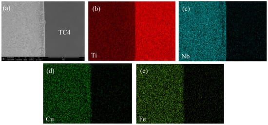
Figure 4.
Distribution of the main elements in the weld metal of titanium alloy side of the welded joints at a welding speed of 6 mm/s (EBW-1), including (a) the back scatter electron (BSE) image, (b) the Ti map, (c) the Nb map, (d) the Cu map, and the (e) Fe map.
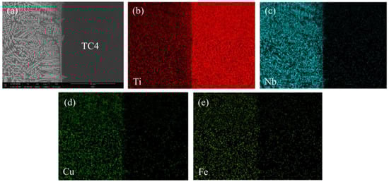
Figure 5.
Distribution of the main elements in the weld metal of titanium alloy side of the welded joints at a welding speed of 10 mm/s (EBW-3), including (a) the BSE image, (b) the Ti map, (c) the Nb map, (d) the Cu map and (e) the Fe map.
3.2.2. Microstructure of the Kovar Alloy Side Interface
Figure 6 depicts the microstructure of the kovar alloy side of welded joints at welding speeds of 6 mm/s and 10 mm/s, respectively. As it can be seen, the increase of welding speed had a significant influence on the microstructure of the weld metal of kovar alloy side. If welding speed was 6 mm/s, two phases formed in the weld metal of the kovar alloy side. The dark globular phases (E zone) were distributed in the weld metal with a white phase (F zone) around them, as labeled with E and F in Figure 6a. According to Song et al. [28], the Cu–Nb binary phase diagram [29], the Fe–Co–Ni ternary phase diagram [30], and the analysis results of chemical compositions (in Table 5), certain phases are recognized as listed in Table 5. The dark globular phase (E zone) and the white phase (F zone) were composed of α-Fe + γ-Fe and (Cu,Nb) solid solution. However, if the welding speed was increased to 10 mm/s, the formation of a dark globular phase (G zone) with different sizes in the kovar alloy side were inhibited, as shown in Figure 6b. Figure 6b depicts the SEM image of the dark globular phase (G zone) produced in the weld metal of the kovar alloy side. As can be seen from Table 5, the chemical composition of the dark globular phase (G zone) indicates that the amount of Cu atoms in this phase was increased, while the amount of Nb atoms in this phase was decreased. Similarly, the dark globular phase (G zone) also consisted of α-Fe + γ-Fe and Cu solid solutions. Moreover, the white phase (H zone) contained a large amount of Cu atoms and a small amount of Fe atoms. According to the Cu–Fe binary phase diagram [31], the white phase (H zone) was mainly composed of Cu solid solution. Hence, in both cases, the brittle Fe–Ti IMCs or Ti–Cu IMCs were not produced the kovar alloy interface side, which was beneficial for the connection of the kovar alloy side. Also, a higher welding speed within a certain range could promote the formation of a Cu solid solution in the weld metal of the kovar alloy side to enhance the toughness of the welded joints.
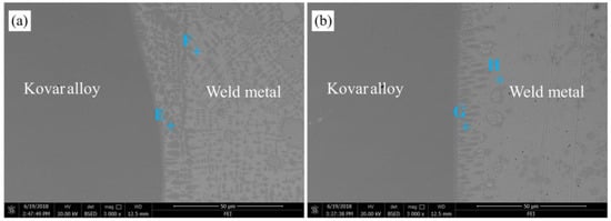
Figure 6.
Microstructure of the kovar alloy side interface of welded joints at welding speeds of (a) 6 mm/s (EBW-1) and (b) 10 mm/s (EBW-3).
Table 5.
The main chemical compositions of different zones (at %) at the kovar alloy side.
3.3. Mechanical Properties of Welded Joints
3.3.1. Micro-Hardness Analysis of Welded Joints
As can be seen from Figure 7, the micro-hardness distribution profile conducted on the cross-section of welded joints at different welding speed is depicted. The location of the hardness measurement is indicated by a white dashed line, as shown in Figure 2. At the titanium alloy side, compared with the welded joint EBW-1, the micro-hardness of weld metal of the welded joint EBW-3 was reduced as a result of the increase of welding speed to 10 mm/s. On the basis of microstructure analysis in Section 3.2.1., the reduction of amount of brittle FeTi decreased the weld metal micro-hardness of the titanium alloy side. Meanwhile, an increase in the amount of (Nb,Ti) solid solution formed in the titanium alloy side of the welded joint at a higher welding speed decreased the micro-hardness of the weld metal, since (Nb,Ti) solid solution has a low hardness [32]. Furthermore, in both cases, near the weld metal, the micro-hardness of titanium alloy was slightly enhanced. In general, as the grain grows, the hardness of HAZ (heat affected zone) will decrease. However, an increase in the β phase can lead to an increase in hardness, because its hardness is higher than that of other phases. Also, the amount of β phase in the HAZ is higher than that in the base metal, so an increase in micro-hardness is found [33]. Compared with the heat-affected zone of titanium alloy, the micro-hardness of the fusion zone of the titanium alloy side is high because of the existence of brittle FeTi. At the kovar alloy side, in both cases, the micro-hardness of the weld metal was increased to about 640 HV. This was because this area that was close to the kovar alloy side contained a high amount of Fe. The Ti atoms easily reacted with the Fe atoms to form brittle Fe–Ti IMCs, which resulted in the increase of micro-hardness in this area. In general, the closer the area to the kovar alloy side is, the greater the possibility of brittle Fe–Ti IMCs being produced. However, at two different welding speeds, the micro-hardness of the weld metal at the kovar alloy interface side began to decrease. According to the microstructure analysis in Section 3.2.2., the formation of the Cu solid solution contributed to the reduction of the weld metal micro-hardness of the kovar alloy interface side. Therefore, it was found that a higher welding speed within a certain range could effectively decrease the micro-hardness of the weld metal to improve the properties of the welded joints.
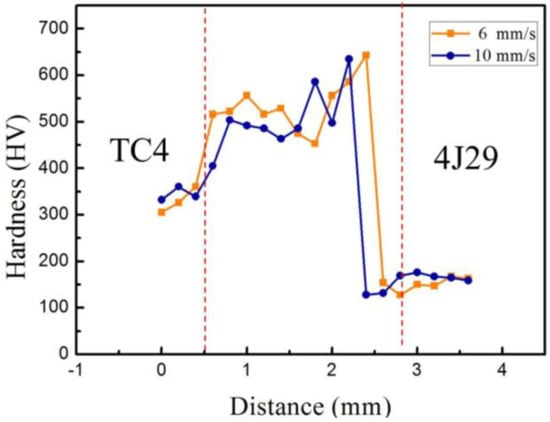
Figure 7.
Micro-hardness distribution across the cross-sections of welded joints at different welding speeds.
3.3.2. Tensile Strength and Fracture Behavior of Welded Joints
Compared with the substrates, the tensile strengths of all the welded joints were extremely low because of insufficient fusion. Due to cracks form in the weld metal, the tensile strength of welded joints EBW-1 and EBW-2 are only 64.28 MPa and 77.83 MPa, respectively. However, if welding speed was 10 mm/s, the tensile strength of welded joint was increased to about 120 MPa, and the stress–strain curve of the welded joint was as shown in Figure 8. The effects of a higher welding speed within a certain range on tensile strength are mainly attributed to the reduction of brittle FeTi and the increase of soft (Nb,Ti) solid solution. Due to the good plasticity and toughness of the (Nb,Ti) solid solution, the tensile strength of the welded joints was increased. Li et al. [22] investigated the laser welded joints of a TiNi alloy and a stainless steel with a Cu interlayer. It was also found that the increase of the welded joints’ tensile strength was attributed to the reduction of FeTi IMCs, and the increase of solid solution. In our previous work, it was found that highest tensile strengths of the welded joints was 150 MPa [18]. Although different welding speeds are used in this work to bond the substrates, the welded joints’ tensile strengths were poor. According to the above analysis, the occurrence of insufficient fusion and the production of brittle FeTi are the main reasons for the poor quality of welded joints. Therefore, it is necessary to adjust the size of the accelerating voltage, the electron beam current, and the focus current, to improve the mechanical properties of the welded joints.
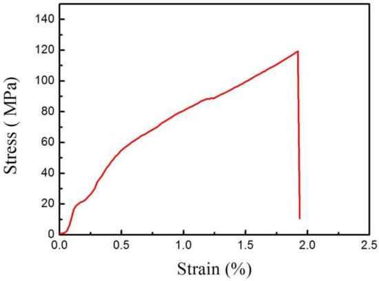
Figure 8.
Stress–strain curve of the welded joint at a welding speed of 10 mm/s.
Figure 9a depicts the fracture surface of the welded joints at a welding speed of 6 mm/s. A fracture surface is the characteristic of brittle fractures, and it exhibits some micro-cracks and river patterns. Combining the analysis of microstructure, by the action of external stress, a crack was easy to form because of the existence of high amounts of brittle FeTi, which then propagated along the thickness direction of the weld metal to result in the fracture of welded joints. If the welding speed was increased to 10 mm/s, as shown in Figure 9b, a tear ridge and some micro-dimples were found in the fracture surface, and this zone may be a linkage step that joins two adjacent non-coplanar crack fronts, signifying a limited ductility region. In this zone, the presence of some brittle IMCs led to the presence of embrittlement in the welded joints. Under the external stress, non-coplanar cracks gradually formed and then propagated to form a tear ridge, which was the reason for the poor ductility of the welded joints. To identify the phase compositions on the fracture surfaces of the welded joints, XRD was conducted on the fracture surfaces of the welded joints EBW-1 and EBW-3, to increase the diffracted intensity [34], as shown in Figure 10. In general, compared with standard diffraction peaks, the locations of diffraction peaks had some discrepancies, because of the complex compositions of the weld metals, and the occurrence of certain distortions of crystal lattices [25]. The results showed that a (Nb,Ti) solid solution and CuTi2 appeared on both of the fracture surfaces of welded joints. However, as can be seen from Figure 10, in both cases, the phases (FeTi, α-Fe + γ-Fe) in the weld metal as observed in SEM were not found by XRD, but Cu0.5Fe0.5Ti appeared on fracture surface. In our previous study, Cu0.5Fe0.5Ti was also detected on the fracture surface by XRD, which was adverse to the mechanical properties of the welded joints [18]. Certain IMCs produced in the weld were inhomogeneous and discontinuous in distribution, and the contents of some IMCs were low, and so some of the IMCs were not detected on the fracture surface when using XRD [25]. In addition, the fracture location was different from the area that was analyzed in SEM; thus, the analytical results of the phase in XRD had discrepancies. Compared with welded joint EBW-1, the Cu solid solution was found on the fracture surface of the welded joint EBW-3, indicating that the fracture location was close to the kovar alloy side, which was beneficial for enhancing the tensile strength of the welded joints. Also, some oxides such as TiO, TiO2, and FeO were found on fracture surface, which resulted from an oxidation reaction when the welded joints were exposed to air.
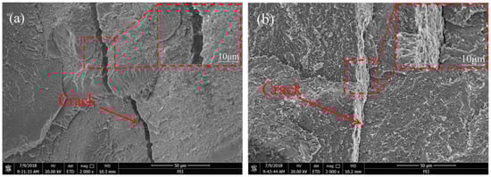
Figure 9.
Fracture surface morphologies of the welded joints at welding speeds of (a) 6 mm/s (EBW-1) and (b) 10 mm/s (EBW-3).
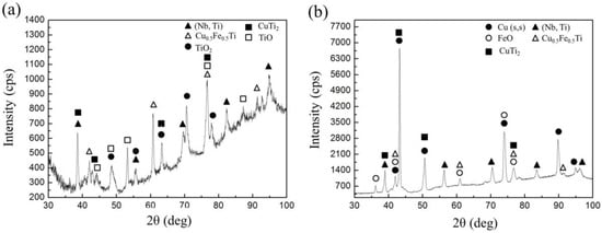
Figure 10.
XRD patterns of fracture surface of welded joints at welding speeds of (a) 6 mm/s (EBW-1) and (b) 10 mm/s (EBW-3).
3.4. Bonding Mechanism
In previous work, the formation process of the fusion zone of the titanium alloy side was analyzed, but it could not reflect the whole bonding process of the welded joints [18]. In this work, on the basis of the above analysis, a higher welding speed within a certain range could effectively restrain the production of FeTi in the weld metal of the titanium alloy side and promote the formation of a solid solution in the weld metal; thus, the welded joints’ tensile strengths were increased to about 120 MPa. Combining the relevant phase diagrams (Cu–Nb [29], Ti–Nb [23], Fe–Co–Ni [30], and Cu–Fe–Ti [24]) and the above analysis, the bonding process of the TC4/Nb/Cu/4J29 dissimilar welded joints EBW-3 mainly includes four steps as follows: first, the partial surface of the substrates can intimately contact with each other to eliminate pores between them, due to the stress of fixture. In first welding, the electron beam is positioned on the surface of the Cu interlayer, and the Fe, Cu, Co, and Ni atoms diffuse and react in the molten pool of the kovar alloy side because of energy input. Meanwhile, the Nb and Cu atoms diffuse towards the interface between the Nb interlayer and the Cu interlayer, as shown in Figure 11a. Second, if temperature decreases to about 800 °C, the Fe, Ni, and Co atoms in the liquid at the front of the liquid/solid interface tend to be saturated, inducing the nucleation of the γ phase. In the molten pool, the Fe, Ni, Co, and Cu atoms are still in a state of diffusion, due to the existence of high temperatures. A small amount of (Cu,Nb) solid solution forms between the Nb interlayer and the Cu interlayer, because of the heat propagation. Meanwhile, the unmelted Cu interlayer remains in the weld because of the high heat conductivity of Cu and the insufficient heat input, as shown in Figure 11b. Third, in the second welding, the electron beam is positioned on the surface of the Nb interlayer, and the Fe, Cu, Nb, and Ti atoms diffuse and react in the molten pool of titanium alloy side. Similarly, if temperature decreases to about 1900 °C, the nucleation of the (Nb,Ti) solid solution occurs in the molten pool. Also, some Cu and Nb atoms still diffuse towards the molten pool of the kovar alloy side due to the second heat input. Meanwhile, the reaction of γ → α-Fe occurs, and the growth process of some grains at the kovar alloy side are almost completes [35]. The globular phase then forms in the molten pool of the kovar alloy side, which is composed of a α-Fe + γ + Cu solid solution, as shown in Figure 11c. Lastly, the columnar dendrite, which is composed of a (Nb,Ti) solid solution and CuTi2, begins to form in a molten pool of the titanium alloy side, because of the increase of constituent super cooling and the decrease of temperature gradient [36]. At the titanium alloy side, if the temperature decreases to about 850 °C, an intergranular phase formed along the grain boundary, which consists of (Nb,Ti) solid solution, Cu0.5Fe0.5Ti, FeTi, and CuTi2. Meanwhile, at the kovar alloy side, Cu solid solution formed along the globular grain boundary, as shown in Figure 11d. In addition, a layer-shaped phase forms on both sides, which was composed of a (Nb,Ti) solid solution + CuTi2 and a α-Fe + γ + Cu solid solution, respectively.
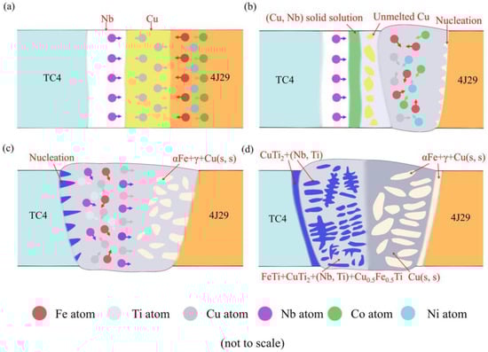
Figure 11.
Schematic presentations of the formation process of the TC4/Nb/Cu/4J29 dissimilar welded joints at a welding speed of 10 mm/s, including (a) material contact, (b) nucleation, and growth of grains of kovar alloy side, (c) nucleation and growth of grains of the titanium alloy side, (d) the production of IMCs and solid solution in the weld metal.
In our further work, we will take two measures to improve the quality of welded joints. First, other composite interlayers could be used in our research, such as V/Cu, V/Fe, Ta/Cu, and so on, which is an advisable method for the enhancement of the mechanical properties of welded joints. Second, the electron beam current, focus current, and accelerating voltage need to be regulated to increase the fusion depth of the weld. In addition, the offset of the electron beam also needs to be adjusted to dominate the location of the energy input.
4. Conclusion
Electron beam welding of a titanium alloy and a kovar alloy with a Cu/Nb multi-interlayer was performed at diverse welding speeds. Also, the effects of welding speed on the weld appearance, mechanical properties, and microstructure of the welded joints were studied. The following major conclusion can be drawn from the present study:
- Metallurgical bonding of a titanium alloy (TC4) and a kovar alloy (4J29) was achieved by using a Cu/Nb multi-interlayer. At welding speeds of 6 mm/s and 8 mm/s, the cracks formed in the weld and the depth of the weld was low. As the welding speed increased to 10 mm/s, the depth of the weld was increased and the formation of the crack was effectively suppressed.
- At the titanium alloy side, increasing the welding speed from 6 mm/s to 10 mm/s, the amount of (Nb,Ti) solid solution was increased, while the formation of brittle FeTi was effectively suppressed. The microstructure of the titanium alloy side was mainly composed of CuTi2, (Nb,Ti) solid solution, and a small amount of FeTi.
- At the kovar alloy side, if the welding speed was increased to 10 mm/s, the formation of Cu solid solution in the weld metal was promoted, which was beneficial for enhancing the toughness of the welded joints. The microstructure of the kovar alloy side mainly consisted of α-Fe, the γ phase, and the Cu solid solution.
- In both cases, Cu0.5Fe0.5Ti was detected on the fracture surface of the welded joints, which could increase the embrittlement of the welded joints. However, a higher welding speed within a certain range was beneficial for eliminating the formation of the crack and inhibiting the embrittlement of welded joints. Therefore, the tensile strength of the welded joints was increased to about 120 MPa at welding speed of 10 mm/s.
Author Contributions
D.M. and Y.W. implemented and conducted the experiments, Y.F. and T.S. characterized the microstructure and mechanical properties of electron beam-welded joints. D.M. and Y.F. analyzed and discussed the results; X.J. revised the manuscript with D.M.; all the authors participated in the design of the experiments and cooperated in writing this paper.
Acknowledgements
This work was funded by the Youth Innovation Promotion Association (Chinese Academy of Sciences), the Key Laboratory of Infrared Imaging Materials and Detectors, Shanghai Institute of Technical Physics, Chinese Academy of Sciences (No. IIMDKFJJ-17-06), Sichuan Science and Technology Support Program (No. 2016FZ0079), the National Natural Science Foundation of China (No. 51201143), the China Postdoctoral Science Foundation (No. 2015M570794, No. 2018T110993), and R&D Project Funding from the Research Council of Norway (No. 263875/H30).
Conflicts of Interest
The authors declare no conflict of interest.
References
- Baghjari, S.H.; Akbari Mousavi, S.A.A. Experimental investigation on dissimilar pulsed Nd:YAG laser weldingof AISI 420 stainless steel to kovar alloy. Mater. Des. 2014, 57, 128–134. [Google Scholar] [CrossRef]
- Adomako, N.K.; Kim, J.O.; Lee, S.H.; Noh, K.H.; Kim, J.H. Dissimilar welding between Ti–6Al–4V and 17-4PH stainless steel using a vanadium interlayer. Mater. Sci. Eng. A 2018, 732, 378–397. [Google Scholar] [CrossRef]
- Song, T.F.; Jiang, X.S.; Shao, Z.Y.; Mo, D.F.; Zhu, D.G.; Zhu, M.H.; Young, C.H.; Luo, Z.P. Interfacial microstructure and mechanical properties of diffusion-bonded joints of titanium TC4 (Ti-6Al-4V) and Kovar (Fe-29Ni-17Co) alloys. J. Iron. Steel. Res. Int. 2017, 24, 1023–1031. [Google Scholar] [CrossRef]
- Chen, H.C.; Bi, G.; Lee, B.Y.; Cheng, C.K. Laser welding of CP Ti to stainless steel with different temporal pulse shapes. J. Mater. Process. Tech. 2016, 231, 58–65. [Google Scholar] [CrossRef]
- Gao, Y.; Nakata, K.; Nagatsuka, K.; Liu, F.C.; Liao, J. Interface microstructural control by probe length adjustment in friction stir welding of titanium and steel lap joint. Mater. Des. 2015, 65, 17–23. [Google Scholar] [CrossRef]
- Qin, B.; Sheng, G.M.; Huang, J.W.; Zhou, B.; Qiu, S.Y.; Li, C. Phase transformation diffusion bonding of titanium alloy with stainless steel. Mater. Charact. 2006, 56, 32–38. [Google Scholar] [CrossRef]
- Mansor, M.S.M.; Yusof, F.; Ariga, T.; Miyashita, Y. Microstructure and mechanical properties of micro-resistance spotwelding between stainless steel 316L and Ti-6Al-4V. Int. J. Adv. Manuf. Tech. 2018, 96, 2567–2581. [Google Scholar] [CrossRef]
- Elrefaey, A.; Tillmann, W. Solid state diffusion bonding of titanium to steel using a copper base alloy as interlayer. J. Mater. Process. Tech. 2009, 209, 2746–2752. [Google Scholar] [CrossRef]
- Kundu, S.; Chakraborty, A.; Mishra, B. Interfacial reaction and microstructure study of DSS/Cu/Ti64diffusion-welded couple. Weld. World. 2018, 62, 155–167. [Google Scholar] [CrossRef]
- Zoeram, A.S.; Rahmani, A.; Mousavi, S.A.A.A. Microstructure and properties analysis of laser-welded Ni–Ti and 316l sheets using copper interlayer. J. Manuf. Process. 2017, 26, 355–363. [Google Scholar] [CrossRef]
- Gao, X.L.; Liu, J.; Zhang, L.J. Dissimilar metal welding of Ti6Al4V and Inconel 718 through pulsed laser welding-induced eutectic reaction technology. Int. J. Adv. Manuf. Tech. 2018, 96, 1061–1071. [Google Scholar] [CrossRef]
- Zhang, Y.; Sun, D.Q.; Gu, X.Y.; Li, H.M. Nd:YAG pulsed laser welding of dissimilar metals of titanium alloy to stainless steel. Int. J. Adv. Manuf. Technol. 2018, 94, 1073–1085. [Google Scholar] [CrossRef]
- Oliveira, J.P.; Panton, B.; Zeng, Z.; Andrei, C.M.; Zhou, Y.; Miranda, R.M.; BrazFernandes, F.M. Laser joining of NiTi to Ti6Al4V using a Niobium interlayer. Acta. Mater. 2016, 105, 9–15. [Google Scholar] [CrossRef]
- Sun, Z.; Karppi, R. The application of electron beam welding for the joining of dissimilar metals: An overview. J. Mater. Process. Tech. 1996, 59, 257–267. [Google Scholar] [CrossRef]
- Wang, T.; Zhang, B.G.; Chen, G.Q.; Feng, J.C. High strength electron beam welded titanium-stainless steel joint with V/Cu based composite filler metals. Vacuum 2013, 94, 41–47. [Google Scholar] [CrossRef]
- Zhang, F.; Wang, T.; Jiang, S.Y.; Zhang, B.G.; Feng, J.C. Microstructural Characteristics and Mechanical Properties of an Electron Beam-Welded Ti/Cu/Ni Joint. J. Mater. Eng. Perform. 2018, 27, 2354–2363. [Google Scholar] [CrossRef]
- Wang, T.; Zhang, B.G.; Feng, J.C.; Tang, Q. Effect of a copper filler metal on the microstructure and mechanical properties of electron beam welded titanium-stainless steel joint. Mater. Charact. 2012, 73, 104–113. [Google Scholar] [CrossRef]
- Fang, Y.J.; Jiang, X.S.; Mo, D.F.; Song, T.F.; Shao, Z.Y.; Zhu, D.G.; Zhu, M.H.; Luo, Z.P. Microstructure and Mechanical Properties of Electron Beam-Welded Joints of Titanium TC4 (Ti-6Al-4V) and Kovar (Fe-29Ni-17Co) Alloys with Cu/Nb Multi-Interlayer. Adv. Mater. Sci. Eng. 2018, 1–11. [Google Scholar] [CrossRef]
- Li, Y.; Zhao, Y.; Li, Q.; Wu, A.; Zhu, R.; Wang, G. Effects of welding condition on weld shape and distortion in electron beam welded Ti2AlNb alloy joints. Mater. Des. 2017, 114, 226–233. [Google Scholar] [CrossRef]
- Soysal, T.; Kou, S.; Tat, D.; Pasang, T. Macrosegregation in dissimilar-metal fusion welding. Acta. Mater. 2016, 110, 149–160. [Google Scholar] [CrossRef]
- Oliveira, J.P.; Zeng, Z.; Andrei, C.; BrazFernandes, F.M.; Miranda, R.M.; Ramirez, A.J.; Omori, T.; Zhou, N. Dissimilar laser welding of superelastic NiTi and CuAlMn shape memory alloys. Mater. Des. 2017, 128, 166–175. [Google Scholar] [CrossRef]
- Li, H.M.; Sun, D.Q.; Gu, X.Y.; Dong, P.; Lv, Z.P. Effects of the thickness of Cu filler metal on the microstructure and properties of laser-welded TiNi alloy and stainless steel joint. Mater. Des. 2013, 50, 342–350. [Google Scholar] [CrossRef]
- ASM International. ASM Handbook Volume 3: Alloy Phase Diagrams; ASM International: Materials Park, OH, USA, 1992; ISBN 978-0-87170-381-1. [Google Scholar]
- Van beek, J.A.; Kodentsov, A.A.; Van Loo, F.J.J. Phase equilibria in the Cu-Fe-Ti system at 1123 K. J. Alloy. Compd. 1995, 217, 97–103. [Google Scholar] [CrossRef]
- Chen, S.H.; Zhang, M.X.; Huang, J.H.; Cui, C.J.; Zhang, H.; Zhao, X.K. Microstructures and mechanical property of laser butt welding of titanium alloy to stainless steel. Mater. Des. 2014, 53, 504–511. [Google Scholar] [CrossRef]
- Zhou, X.W.; Chen, Y.H.; Huang, Y.D.; Mao, Y.Q.; Yu, Y.Y. Effects of niobium addition on the microstructure and mechanical properties of laser-welded joints of NiTiNb and Ti6Al4V alloys. J. Alloy. Compd. 2018, 735, 2616–2624. [Google Scholar] [CrossRef]
- Tomashchuk, I.; Sallamand, P.; Belyavina, N.; Pilloz, M. Evolution of microstructures and mechanical properties during dissimilar electron beam welding of titanium alloy to stainless steel via copper interlayer. Mater. Sci. Eng. A 2013, 585, 114–122. [Google Scholar] [CrossRef]
- Song, T.F.; Jiang, X.S.; Shao, Z.Y.; Mo, D.F.; Zhu, D.G.; Zhu, M.H. The interfacial microstructure and mechanical properties of diffusion-bonded joints of 316l stainless steel and the 4J29 kovar alloy using nickel as an interlayer. Metals 2016, 6, 263. [Google Scholar] [CrossRef]
- Okamoto, H. Cu-Nb (Copper-Niobium). J. Phase. Equilib. Diff. 1991, 12, 614–615. [Google Scholar] [CrossRef]
- Raghavan, V. Co-Fe-Ni (cobalt-iron-nickel). J. Phase Equilib. 1994, 15, 526–527. [Google Scholar] [CrossRef]
- Turchanin, M.A. Thermodynamics of Liquid Alloys, and Stable and Metastable Phase Equilibria in the Copper-Iron System. Powder. Metall. Met. Ceram. 2001, 40, 337–353. [Google Scholar]
- Torkamany, M.J.; Ghaini, F.M.; Poursalehi, R. Dissimilar pulsed Nd:YAG laser welding of pure niobium to Ti–6Al–4V. Mater. Des. 2014, 53, 915–920. [Google Scholar] [CrossRef]
- Gope, D.K.; Kumar, U.; Chattopadhyaya, S.; Mandal, S. Experimental investigation of pug cutter embedded TIG welding of Ti-6Al-4V titanium alloy. J. Mech. Sci. Technol. 2018, 32, 2715–2721. [Google Scholar] [CrossRef]
- Kundu, S.; Anand, G.; Chatterjee, S. Diffusion bonding of 17–4 precipitation hardening stainless steel to Ti alloy with and without Ni alloy interlayer: Interface microstructure and mechanical properties. Metall. Mater. Trans. A 2013, 44, 2196–2211. [Google Scholar] [CrossRef]
- Sourmail, T. Near equiatomic FeCo alloys: Constitution, mechanical and magnetic properties. Prog. Mater. Sci. 2005, 50, 816–880. [Google Scholar] [CrossRef]
- Li, G.; Lu, X.F.; Zhu, X.L.; Huang, J.; Liu, L.W.; Wu, Y.X. The defects and microstructure in the fusion zone of multi-pass laser welded joints with Inconel 52M filler wire for nuclear power plants. Opt. Laser. Technol. 2017, 94, 97–105. [Google Scholar] [CrossRef]
© 2018 by the authors. Licensee MDPI, Basel, Switzerland. This article is an open access article distributed under the terms and conditions of the Creative Commons Attribution (CC BY) license (http://creativecommons.org/licenses/by/4.0/).