Article

A Tool for Predicting the Effect of the Plunger Motion Profile on the Static Properties of Aluminium High Pressure Die Cast Components

Department of Management and Engineering (DTG), University of Padova, Vicenza 36100, Italy
*
Author to whom correspondence should be addressed.
Metals 2018, 8(10), 798; https://doi.org/10.3390/met8100798
Submission received: 1 September 2018 / Revised: 29 September 2018 / Accepted: 30 September 2018 / Published: 5 October 2018
(This article belongs to the Special Issue Processing-Structure-Property Relationships in Metals)

Abstract

:
The availability of tools for predicting quality in high pressure die casting is a challenging issue since a large amount of defects is detected in components with a consequent worsening of the mechanical behavior. In this paper, a tool for predicting the effect of the plunger motion on the properties of high pressure die cast aluminum alloys is explained and applied, by demonstrating its effectiveness. A comparison between two experiments executed through different cold chamber machines and the same geometry of the die and slightly different chemical compositions of the alloy is described. The effectiveness of the model is proved by showing the agreement between the prediction bounds and the measured data. The prediction model proposed is a general methodology independent of the machine and accounts for the effects of geometry and alloy through its coefficients.

1. Introduction

High pressure die casting (HPDC) is widely used for manufacturing components with high integrity and productivity. Nevertheless, porosity, oxides and undesired structures are frequent and could cause premature failure of the components obtained through HPDC [1]. The quality and the mechanical properties of the parts depend on the features of the whole process [2], including the die (such as geometry, the nozzle position, mold surface features related to friction and coating [3]), the temperature, the chemical composition of the injected alloy, the pressure exerted by the injection machine and the motion profile of the plunger. Hence, the optimization of HPDC relies on a wise selection of all these factors. Several approaches have been proposed in the literature to forecast the achievable properties. A common approach is the use of numerical simulations through finite element modelling or computational fluid dynamics methods, which allow studying the metal flow (and hence the detrimental presence of turbulence) and the thermal behavior [4]. Simulation is, for example, the most effective method in the optimal design of the die, to optimize its geometry, the runners, the sprues and the venting system [5].
A different approach is the one based on the use of metamodels, i.e., simplified behavioral models that provide and abstract representation of the relations between some meaningful process parameters and the casting properties of interest [6]. Non-physical interpolation schemes and artificial-intelligence approaches have been also recently proposed in literature to model the casting properties as a function of many parameters, such as neural networks [7], high-order response surfaces [8] or multivariable regression based on the Taguchi method [9].
Among the process parameters, a meaningful contribution is made by the so-called kinematic parameters of the plunger of the injection machine (i.e., its displacement, speed and acceleration), and several works have been focused on this issue [10,11]. Indeed, modifying the motion profile of the plunger is usually straightforward and costless, and a proper choice can boost the achievement of the best properties allowed by the available combination of die and alloy. In contrast, a bad selection of the plunger motion profile drastically downgrades the properties of the casting. Although it is widely recognized that the plunger motion plays a relevant role in the final quality of castings, a comprehensive methodology to predict the outcome in HPDC has not yet been proposed in the literature. Indeed, most of the works neglect the time history of the plunger motion, by attempting to summarize it just with its maximum instantaneous value, i.e., the peak value that might be achieved for just an instant of the second stage, and with the constant velocity of the process first stage. The first stage velocity is related to the filling of the die casting machine chamber, while the second stage velocity is associated with the filling of the die cavity. These parameters are often used by practitioners to plan the process and to correlate it with the casting quality. However, the correlations provided by these parameters are often conflicting and not predictive, thus they should be used only for preliminary evaluations and cannot be applied for the a priori optimization of the process. Indeed, just considering their value neglects how these values have been reached and how long the plunger holds these values. In other terms, there is still no consensus in the open domain on the effect of plunger motion on mechanical properties of aluminum alloy HPDCs [11].
A reliable prediction model that accounts for the influence of the process on the static mechanical behavior and the internal quality of castings is still missing in the literature, except for the concepts and the methodology proposed in the previous work of the authors [6,12,13]. Such works propose a scalar parameter that summarizes the time-history of the plunger motion, through its acceleration, and allows for the comparison of different motion profiles having different shapes (i.e., different mathematical primitives), different maximum speed or first-stage speed. The capability of such a parameter to get rid of these features, as well as of the characteristics of the injection machine used and in the presence of some uncertainty (or small variations) of other process parameters, is evaluated in this paper. By taking advantage of the experiment proposed in the previous work of the authors in [12], a prediction behavioral model was developed and validated through a new experimental campaign whose castings were manufactured with an identical die in a different plant. Thus, a different machine was employed, with different shapes of the motion profiles and with some small deviations from the other process conditions. The comparison of the actual mechanical properties and the ones predicted by the model corroborates the correctness of the approach and the possibility to optimize HPDC through the proposed behavioral model.

2. Theoretical Concepts

The use of constant or instantaneous process parameters, such as first stage speed, second stage peak speed and the switching position between the two stages, is not sufficient to predict the casting quality. Indeed, these instantaneous values are not representative of the time history of the plunger motion. This lack of accuracy of such a traditional approach is exacerbated if different machines and motion profiles are compared. Indeed, plunger motion profiles with a different shape might have the same peak values, but they lead to considerably different casting properties.
To overcome this limitation, [12,13] proposed the use of novel kinematic parameters that account for the time history of the plunger motion, rather than just some instants, to represent physical phenomena that are not instantaneous but last finite intervals. Indeed, integral parameters collect more information than instantaneous parameters and are more meaningful to explain and predict the casting properties. Among these parameters, the root mean square (RMS) acceleration of the second stage was proved in [12,13] to be very effective. Such a kinematic parameter is defined as follows:
a R M S = t s 2 t e 2 x ¨ ( t ) 2 d t t e 2 t s 2 .
t is the time, x ( t ) denotes the plunger displacement, x ¨ ( t ) is the acceleration, t e 2 t s 2 is the duration of the second stage, which begins at t = t s 2 (i.e., the switching time) when the plunger reaches the switching position and ends when it reaches the final position at t = t e 2 (i.e., the instant when the second stage ends and the upset pressure stage starts). Equation 1 highlights the integral nature of a R M S that is suitable for modelling a process with a physical integral nature, whose outcome depends on the time history. a R M S can be computed both numerically through the measured plunger displacement curve, and analytically through some notable points and the knowledge of the primitive motion (i.e., the function in time that represents the displacement) [6].
a R M S has an intuitive physical interpretation, and represents the average value of the inertial forces of the plunger over the interval of integration (for unitary masses). Hence, by expressing the Newtonian dynamic equilibrium of the plunger, a R M S is a measure of the force transmitted to the melt by the plunger during the second stage. Higher a R M S means higher forces over the whole second stage, that strive against defects by fragmenting oxides and by making bubbles of entrapped gas collapse [12], thus boosting quality and mechanical strength.
A simple mono-variable fitting model can be assumed to relate to a R M S and the mechanical properties, thus preventing overfitting due to high order models. In [12], a “less-than-linear” relation between the peak load, F m a x , and a R M S was suggested and proved to be effective:
exp ( F m a x ) = α 0 + α 1 a R M S .
An alternative formulation of Equation (2), that represents the same “less-than-linear” effect, is a linear relation between F m a x and log( a R M S ).
The terms α 0 and α 1 in Equation (2) are coefficients to be identified through least-square fitting. Coefficient α 0 can be thought of as a “mean” (or reference) value of the achievable peak load. The coefficient α 1 represents, instead, the variability of the peak load when the process is modified. This is a common interpretation in the field of metamodeling.
The values of the coefficients mainly depend on the following factors.
  • The chemical composition of the alloy. A wide literature (see e.g., the review paper [14] and the references therein, and [15]) shows that the content of alloying elements modifies the mean value of the achievable mechanical behavior. Thus, it mainly affects the coefficient α 0 .
  • The geometry of the die [4,5,11,16,17]. Badly designed dies impose optimal plunger motion to improve quality since their shapes boost the generation of defects. This includes both the geometry of the cavity, as well as the position and the design of the nozzle. Hence, a large variability of the casting strength is obtained as the plunger motion varies. In contrast, optimized dies make the casting quality less sensitive to process parameters and therefore smaller drifts of the properties are expected when modifying the acceleration. Hence, coefficient α 1 , representing the variability of the achieved peak load, is strongly affected by the geometry of the die. Indeed, the slope of the fitting model will be low in the case of optimized geometries [6], while it will be steeper in the case of “defect-generating” dies like those adopted in this work and in [12,18]. Also, the friction between the die and the flowing metal has a similar effect: in the presence of high friction forces, the flow is perturbed unless a proper selection of the plunger motion profile is chosen, thus exacerbating the defect generation with badly planned plunger motion.
  • The thermal properties of the casting system [18,19,20]. The temperatures of melt, chamber and die, besides the characteristics of thermoregulation and lubrication systems optimize heat removal by improving the microstructure of castings and hence the static strength. The thermal properties have an influence on both the coefficients since they affect the filling of the die cavity and the solidification of the melt, which in turn are related to the chemical composition of the alloy and the geometry of the die.
In contrast, changes in the features of the injection machine (e.g., maximum allowable speed, acceleration, jerk, force), as well as in the shape of the motion profile (in particular in the shape of the second stage), do not cause meaningful variations of the model coefficients. This thesis will be assessed in this paper and is an important feature of the proposed kinematic parameter a R M S , which makes it suitable for the characterization of the properties of a die–alloy combination, i.e., by assuming the die geometry and the chemical composition. Indeed, once the coefficients of a die–alloy combination have been identified through experimental or simulation analysis, the model obtained can be applied to different injection machines, provided that the other parameters that affect the coefficients (i.e., thermal properties, as discussed in the previous bullet points) are similar to those used to synthesize the model. Hence, an effective tool to optimize HPDC in different plants through the selection of the optimal motion of the injection machine is obtained. For example, the model is useful for evaluating the impact of modifying the motion profile due to different speed and acceleration limits, as well as the scaling-in-time [13,21] of the motion profile.
Given the availability of the prediction model in Equation (2) and of the knowledge of the injection machine kinematic limitations (see e.g., [13] for a discussion on the effect of the kinematic and dynamic limitations), process optimization is finally performed by looking for the feasible plunger motion profile ensuring higher a R M S .

3. Experimental Assessment

3.1. Description of the Test Case

Two experimental campaigns were executed with two different casting machines, the same die geometry and slightly different alloy chemical compositions. The manufacturing of the castings was realized by two different plants. Both the machines have 7355 kN locking force, while they have different plunger diameters of 0.080 and 0.070 m [12,18]. The die was designed to exacerbate the defect generation [22]. Bending test specimens were trimmed from the flat appendixes of the casting shown in Figure 1, with 0.04 m width, 0.002 m thickness and 0.06 m length.
An AlSi9Cu3 (Fe) alloy was cast in both the tests, corresponding to the EN AB-46000 aluminum alloy (European designation, equivalent to the US designation A380). The chemical compositions are reported in Table 1.
In both the experimental campaigns, care was taken to reduce the gas content by slowly and manually stirring the molten metal in the furnace with a coated paddle. Moreover, a powder lubricant was used in the shot sleeve for the plunger to minimize the hydrogen content. Different amounts of gas were therefore treated as uncertainty in the two processes: an effective tool for predicting mechanical properties should remove this uncertainty.
The design of the experiments was planned by changing the first stage constant speed, the second stage peak speed and the switching position between the two stages (see Table 2). The range of variation of these parameters was set as large as possible depending on the machine characteristics and constraints (flow limitations of the hydraulic actuator and on the maximum pressure exerted by the plunger [13,23]). The lower bound of the feasible acceleration was related to the need to avoid incomplete castings, while the upper bound was related to the need to minimize flash formation due to the melt leakage through the gap between the die parts [24]. It should be observed that this upper limit is not related to problems in the filling of the die cavity, but rather to technical limitations of the die casting machine in terms of locking force.
Different combinations of process sets have been chosen. A central level plus some additional levels were chosen between the lower and the upper levels, by applying the Sobol experiment design [25], which allows the effective covering of the experiment domain. Moreover, the different shapes (primitives) of the motion laws adopted in the second stage were evaluated, besides the most common one, which is the fifth degree polynomial displacement profile [13], to verify the robustness of a R M S as a predicting factor.
In the second experimental campaign, other parameters were slightly changed, such as upset pressure, temperatures of the melt and of the die, even if the precise evaluation of the impact of these parameters goes beyond the aim of this work and is discussed in [18]. The same paper, however, shows that a R M S is by far the most relevant parameter that explains the differences of the casting properties. Hence, the variations of pressure or temperature have been neglected in this analysis and treated as further disturbance factors.
The machines were instrumented with a position sensor recording the plunger displacement with the sample time ∆t = 0.5e − 3 s. Speed and acceleration were computed through the numerical methods in [12].
In the first experimental campaign, 32 different combinations of parameters were tried, and each combination was manufactured with a number of repetitions ranging from three to seven. This number of repetitions was chosen to ensure that the sample is meaningful under a statistical point of view (around 90 castings). In particular, seven repetitions were chosen for some critical motion profiles with higher jerk and which are therefore difficult to track by the actuation system and the controller. In the second experiment, 40 castings were manufactured.
As for the quality assessment, the bending peak load was measured on the flat appendixes of the casting, as explained at the beginning of this section. Moreover, the fracture surfaces of some selected castings were analyzed using a scanning electron microscope (FEG-SEM Quanta 250 of ThermoFisher, Hillsboro, OR, USA), while the zones near the fracture surface were analyzed using an optical microscope (Leica Microsystems, Wetzlar, Germany) to study some microstructural features.

3.2. Analysis of the Shape of the Plunger Motion Profile

a R M S is a practical and comprehensive quantity for comparing castings obtained with different plunger motion profiles since it summarizes the second stage. Conversely, instantaneous values are not suitable since they do not represent the time history of the plunger motion. For example, different motion profiles might have the same peak velocity, but a significantly different time history (in terms of both speed and acceleration), and therefore such an instantaneous parameter is not suitable for proper comparisons. It is also worth noticing that motion laws with very similar position profiles might result in significantly different acceleration and hence a R M S [21].
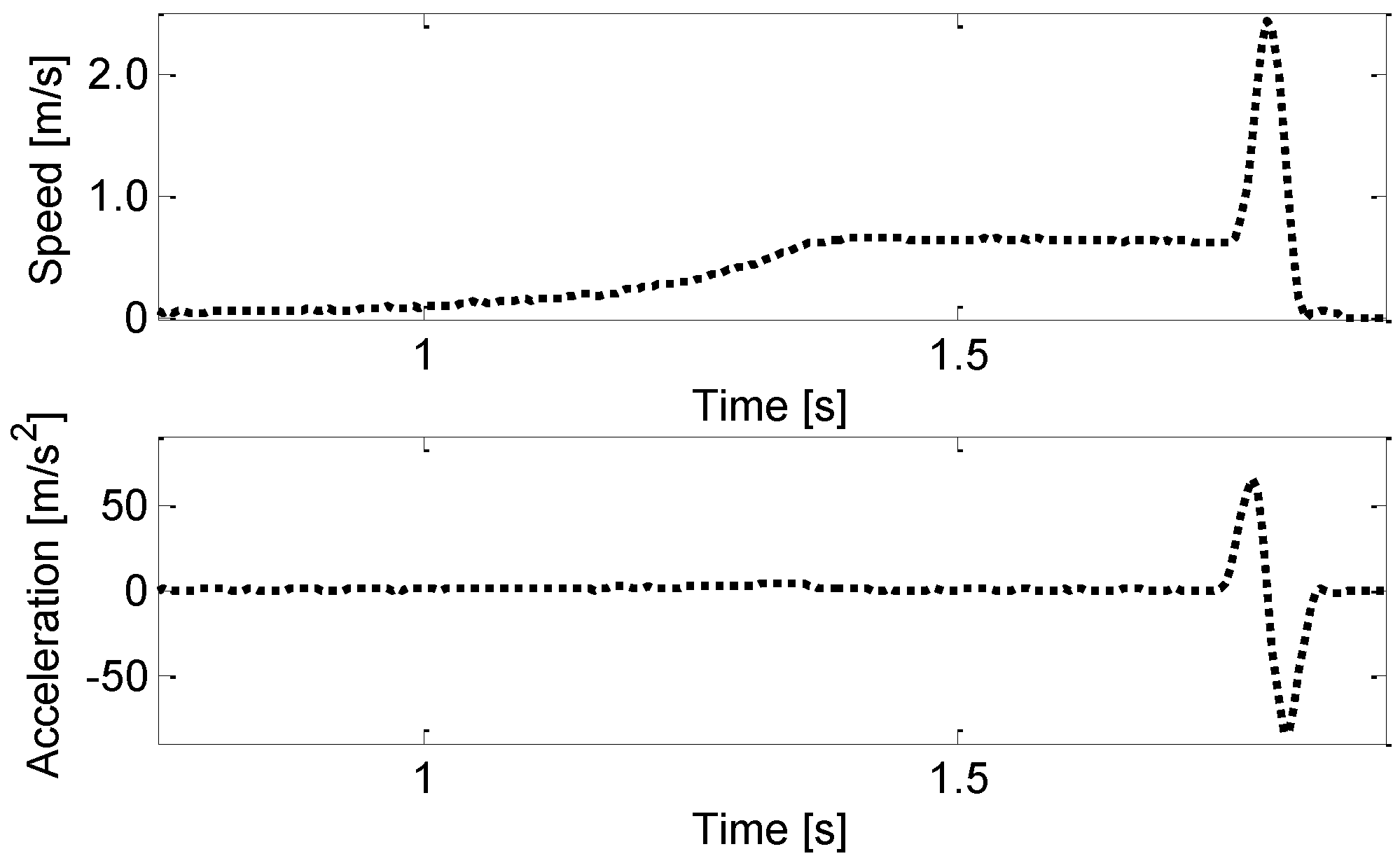
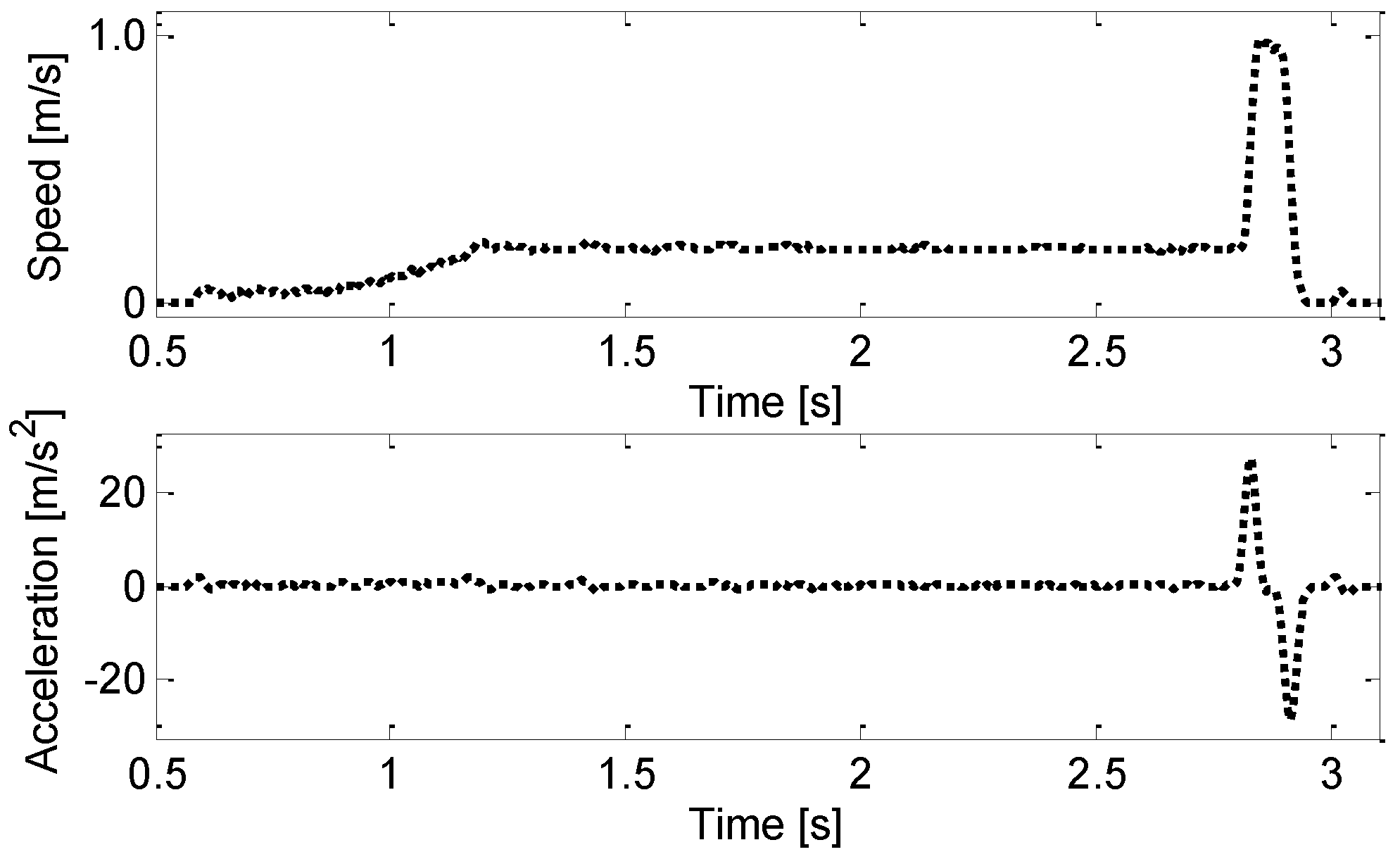
To show this important feature of a R M S , the castings of the two experimental campaigns were manufactured by means of different profiles by changing the motion primitives (together with the parameters stated in Table 2). To notice the differences at a glance, some meaningful examples of the motion profiles are shown in Figure 2, Figure 3, Figure 4 and Figure 5. These sample figures were taken from the second experiment, which has a high variety of motion primitives, and were chosen among the 130 curves of the 130 castings manufactured to highlight the presence of very different speed and acceleration profiles. All the motion profiles have a continuous acceleration, and therefore a finite jerk, to ensure feasibility. Therefore, piecewise-constant acceleration profiles, like those often used in other engineering fields because of their simple formulation have not been tested since they cannot be accurately tracked by injection machines.
Figure 2 shows an example of the fourth degree polynomial speed profile adopted in the second stage, and the corresponding quasi-symmetric third degree acceleration profile. This motion law is often adopted in servo-controlled hydraulic injection machines [23], since a fifth degree displacement polynomial is feasible because of its smoothness [12,21]. This type of motion profile was the one adopted in the first experimental campaign to develop the prediction model and to obtain the model coefficients.
A slightly different speed curve is shown in Figure 3. Compared with Figure 2, the peak speed was held for a finite time thus imposing null accelerations in such an interval.
A significantly different shape was obtained by holding a quasi-constant speed approaching the peak speed, for a long interval (see Figure 4). Hence, the acceleration had steeper variations (jerk) at the beginning and the end of the die cavity filling, while approaching zero within this interval.
The last sample of motion profile was represented in Figure 5, which shows a speed curve with a high first stage velocity (reached after a long parabolic transient) and an asymmetric acceleration.

4. Results and Discussion

4.1. Prediction Model Application

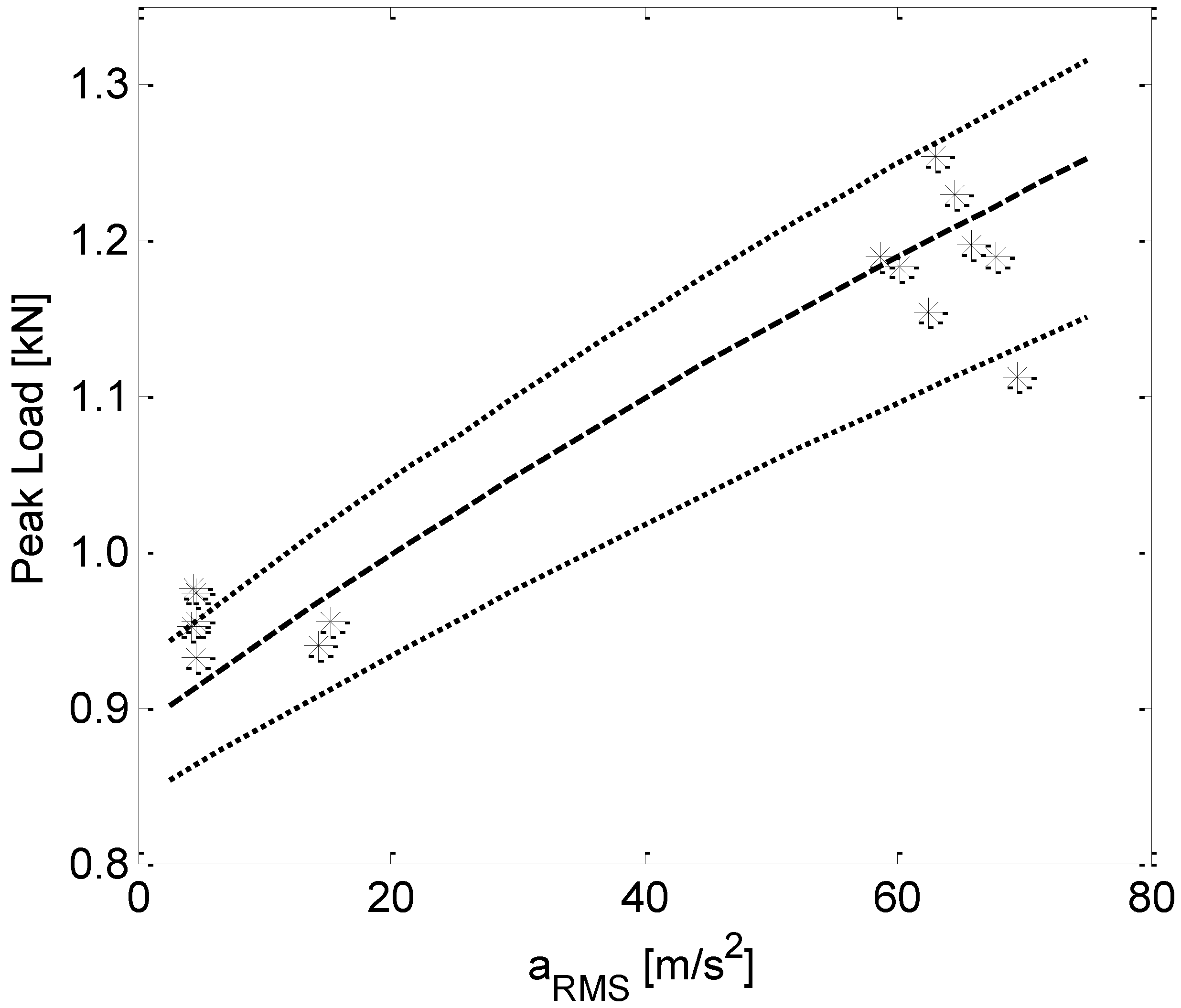
The prediction model was obtained from the first experimental campaign and was applied on the castings of the second experiment. The model coefficients obtained through fitting in [12] were α 0 = 2.40 [exp(kN)] and α 1 = 0.0145 [exp(kN) s2/m] and were used to define the domain of the prediction model. The model is depicted in Figure 6 through dashed lines, and was compared with the experimental data of the second experiment, represented by the symbols *. The central line is the fitting model, while the upper and lower bound lines (represented through dotted lines) are the 95% confidence interval of the model. The good agreement between the prediction and the actual properties of the castings is evident, despite the unavoidable random and uncontrollable effects that affect HPDC and the slightly different chemical compositions.
The consistency of the measured data with the prediction model was confirmed by the model obtained by directly fitting the measured data of the second experimental campaign through Equation (2), leading to α 0 = 2.47 [exp(kN)] and α 1 = 0.0150 [exp(kN) s2/m]. These values were almost identical to those of the prediction model.
It is worth noting that the proposed prediction model is robust also in extrapolation, since the range of a R M S is different in the two experimental campaigns (see Table 2). Indeed, the lower bound of a R M S was approximately 17 m/s2 in the first experimental campaign, while it was around 4 m/s2 in the second one. As for the upper bound, it was approximately 81 m/s2 in the first experiment and 69 m/s2 in the second one.
The coherence between the prediction model and the measured data proves the reliability and the robustness of a R M S , even when using injection machines with different characteristics and in the presence of different shapes of the motion profile.

4.2. Metallographic Analyses

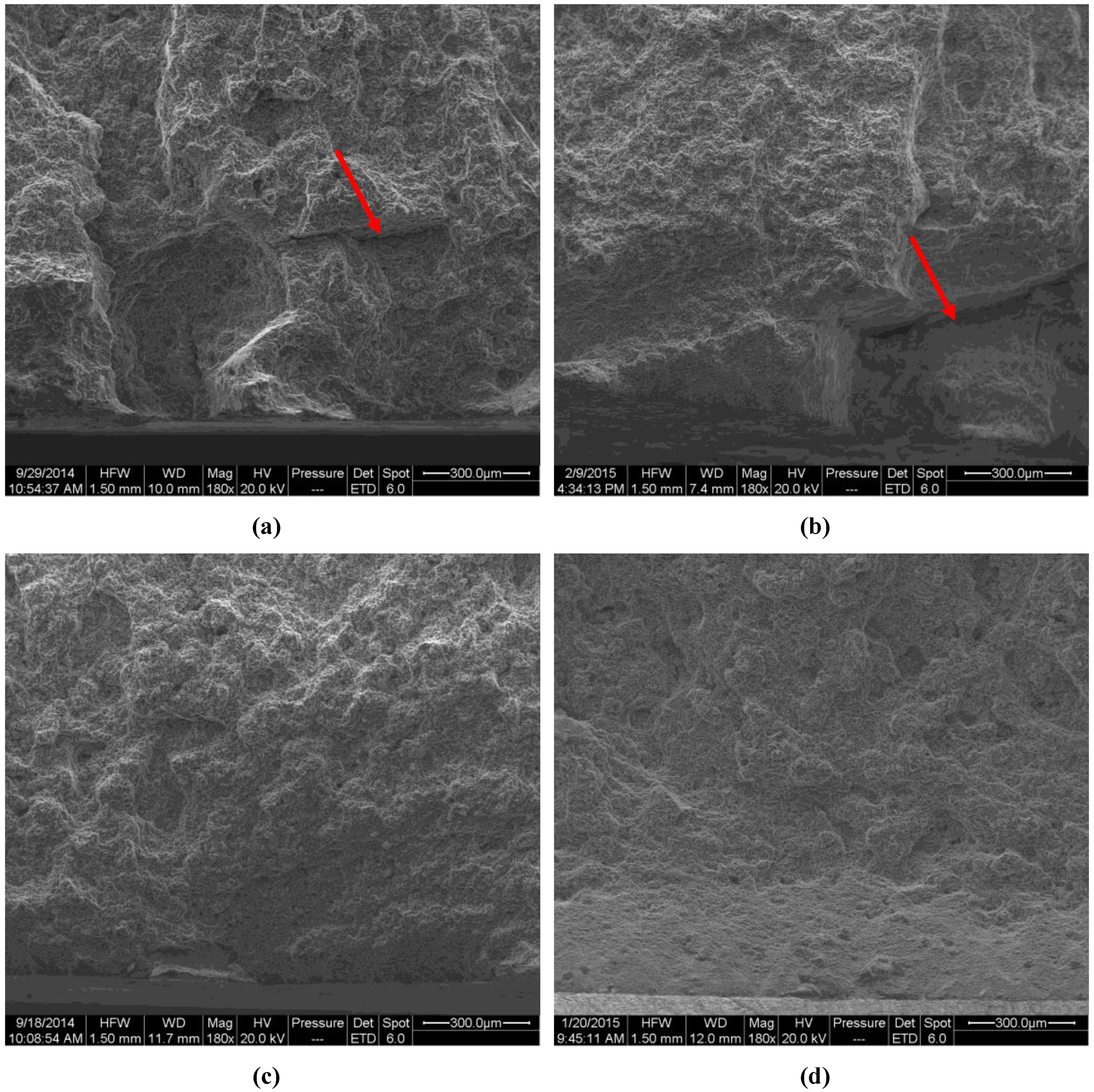
As further evidence, the fracture surfaces of some castings with opposite values of a R M S (and similar values of all the other process conditions) were analyzed by SEM (see Figure 7). The comparison of the fracture surfaces of the castings confirmed that high a R M S boosts the achievement of high-integrity castings with a very low oxide percentage, regardless of the casting machines and the shapes of the motion profiles. Clearly, the castings with a lower bending peak load were those with higher percentages of oxides and gas bubbles, since the low values of a R M S cause low forces that strive against these detrimental defects. In Figure 7, the defects are marked by red arrows.
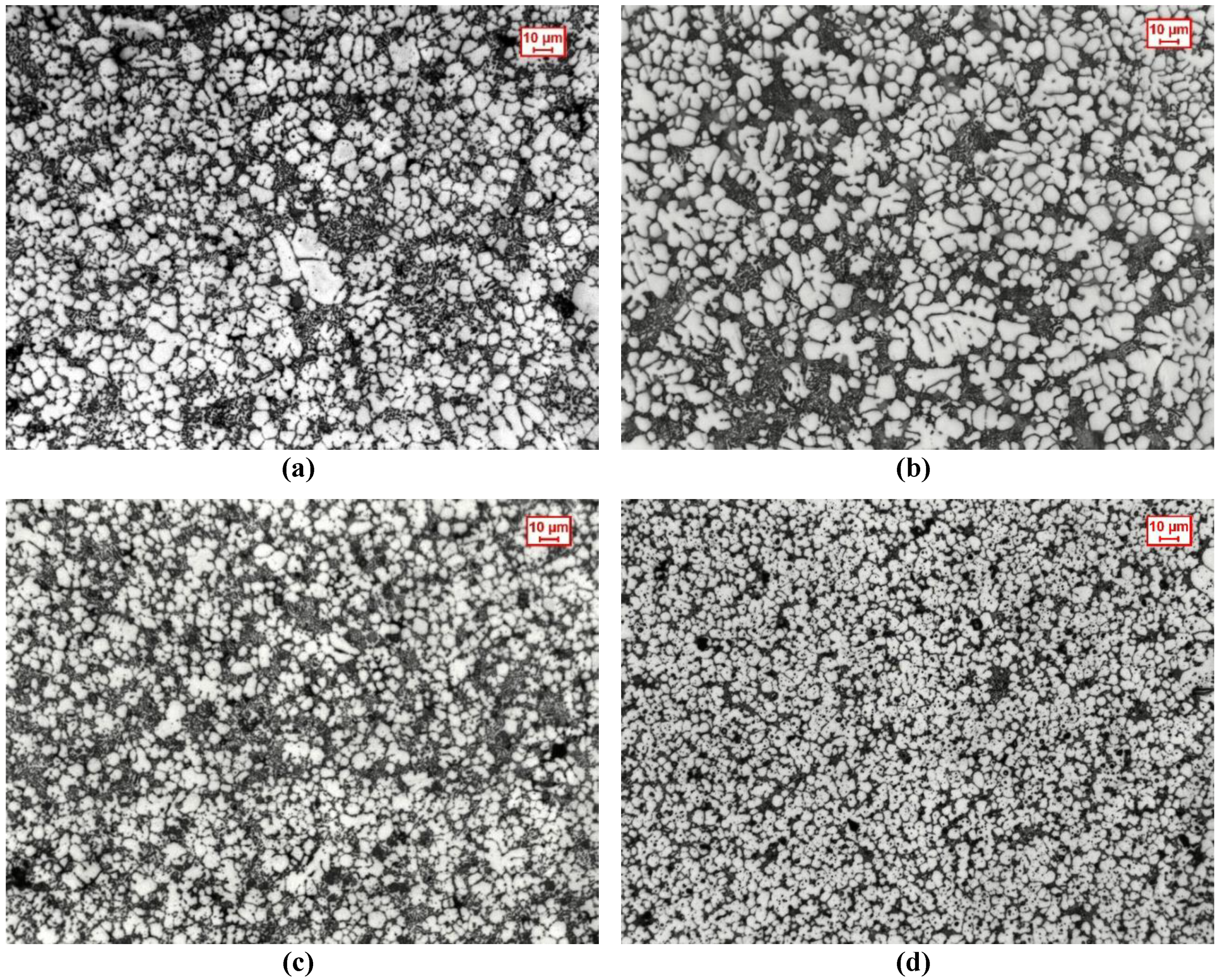
Sample castings of the two experiments were also analyzed by optical microscope after etching to observe their microstructural features as functions of Si content and a R M S . Indeed, the difference in chemical composition between the two Al alloys results in different fractions of eutectic, as shown in Figure 8: the higher content of Si resulted in higher eutectic fraction, which is in agreement with the literature (see e.g., [26]). Figure 8 also corroborates that higher values of a R M S have positive effects on the casting microstructure. Indeed, by comparing the four pictures, it is evident that increasing the acceleration boosts the achievement of a finer microstructure. The positive effects of the plunger motion on the microstructure are corroborated by other research proposed in the literature (see e.g., [27,28]). Indeed, the increasing melt and acceleration multiplied the number of smaller alpha-Al grains at the expense of the larger grains since higher forces, and also higher shear at the gates, break down the larger grains into smaller and rounded forms. Additionally, the increased forces due to melt acceleration contribute to remove more dendritic fragments and contribute to the refinement of gas bubbles trapped earlier in the shot sleeve and/or in the runner.

5. Conclusions

A numerical tool for predicting the effect of the motion profile for the optimization of high pressure die cast aluminum alloys was explained and validated through the comparison of two experiments carried in different plants, with different cold chamber machines and slightly different chemical compositions of the alloy. The parameter was the root mean square value of the plunger acceleration in the second stage of the process, a R M S , and it proved to have a significant influence on the static mechanical behavior and the microstructural features of castings. A prediction model was synthesized through a first experimental campaign, and then applied to forecast the properties of the castings manufactured by a different plant, with a different injection machine and different plunger profiles. The results obtained are in agreement with the theoretical expectations.
Given the coherence between the prediction model, it is evident that a R M S is a practical and comprehensive quantity for comparing castings obtained with different plunger motion profiles and different motion primitives, since it summarizes the story of the whole second stage of HPDC.
Hence, process optimization can be performed by looking for the feasible plunger motion profile ensuring higher a R M S and the resulting strength can be predicted through the model once the model parameters have been estimated.

Author Contributions

Conceptualization, E.F. and F.B.; Methodology, E.F.; Software, E.F.; Validation, E.F., E.B. and F.B.; Formal Analysis, E.F.; Investigation, E.F., E.B. and F.B.; Resources, F.B.; Data Curation, E.F.; Writing-Original Draft Preparation, E.F.; Writing-Review & Editing, E.F., E.B. and F.B.; Visualization, E.F., E.B. and F.B.; Supervision, F.B.; Project Administration, F.B.; Funding Acquisition, F.B.

Funding

This research was funded by the European MUSIC Project N. 314145.

Acknowledgments

The authors would like to acknowledge the contribution of the project partners EnginSoft, Saen, Electronics and GTA. Moreover, the authors are also grateful to the following peoples for their contribution to the experimental activity: Lothar Kallien and Martina Winkler (foundry laboratory of Aalen University of Applied Sciences, Germany), Enrico Della Rovere and Giacomo Mazzacavallo (University of Padova, Department of Management and Engineering, Italy).

Conflicts of Interest

The authors declare no conflict of interest.

References

  1. Tian, C.; Law, J.; Van Der Touw, J.; Murray, M.; Yao, J.Y.; Graham, D.; John, D.S. Effect of melt cleanliness on the formation of porosity defects in automotive aluminium high pressure die castings. J. Mater. Process. Technol. 2002, 122, 82–93. [Google Scholar] [CrossRef]
  2. Bonollo, F.; Gramegna, N.; Timelli, G. High-pressure die-casting: Contradictions and challenges. JOM 2015, 67, 901–908. [Google Scholar] [CrossRef]
  3. Nunes, V.; Silva, F.J.G.; Andrade, M.F.; Alexandre, R.; Baptista, A.P.M. Increasing the lifespan of high-pressure die cast molds subjected to severe wear. Surf. Coat. Technol. 2017, 332, 319–331. [Google Scholar] [CrossRef]
  4. Pinto, H.; Silva, F.J.G. Optimisation of die casting process in Zamak alloys. Procedia Manuf. 2017, 11, 517–525. [Google Scholar] [CrossRef]
  5. Silva, F.J.G.; Campilho, R.D.S.G.; Ferreira, L.P.; Pereira, M.T. Establishing Guidelines to Improve the High-Pressure Die Casting Process of Complex Aesthetics Parts. In Transdisciplinary Engineering Methods for Social Innovation of Industry 4.0, Proceedings of the 25th ISPE Inc. International Conference on Transdisciplinary Engineering, Modena, Italy, 3–6 July 2018; Peruzzini, M., Pellicciari, M., Bil, C., Stjepandić, J., Wognum, N., Eds.; IOS Press: Modena, Italy, 2018; Volume 7, pp. 887–896. [Google Scholar]
  6. Fiorese, E.; Richiedei, D.; Bonollo, F. Improved metamodels for the optimization of high-pressure die casting process. Metall. Ital. 2016, 108, 21–24. [Google Scholar]
  7. Kittur, J.K.; Patel, G.M.; Parappagoudar, M.B. Modeling of pressure die casting process: An artificial intelligence approach. Int. J. Met. 2016, 10, 70–87. [Google Scholar] [CrossRef]
  8. Kittur, J.K.; Choudhari, M.N.; Parappagoudar, M.B. Modeling and multi-response optimization of pressure die casting process using response surface methodology. Int. J. Adv. Manuf. Technol. 2015, 77, 211–224. [Google Scholar] [CrossRef]
  9. Hsu, Q.C.; Do, A.T. Minimum porosity formation in pressure die casting by Taguchi method. Math. Prob. Eng. 2013, 2013, 1–9. [Google Scholar] [CrossRef]
  10. Verran, G.O.; Mendes, R.P.K.; Dalla Valentina, L.V.O. DOE applied to optimization of aluminum alloy die castings. J. Mater. Process. Technol. 2008, 200, 120–125. [Google Scholar] [CrossRef]
  11. Gunasegaram, D.R.; Givord, M.; O’Donnell, R.G.; Finnin, B.R. Improvements engineered in UTS and elongation of aluminum alloy high pressure die castings through the alteration of runner geometry and plunger velocity. Mat. Sci. Eng. A 2013, 559, 276–286. [Google Scholar] [CrossRef]
  12. Fiorese, E.; Bonollo, F. Plunger kinematic parameters affecting quality of high-pressure die-cast aluminum alloys. Metall. Mater. Trans. A. 2016, 47, 3731–3743. [Google Scholar] [CrossRef]
  13. Fiorese, E.; Richiedei, D.; Bonollo, F. Improving the quality of die castings through optimal plunger motion planning: Analytical computation and experimental validation. Int. J. Adv. Manuf. Technol. 2017, 88, 1475–1484. [Google Scholar] [CrossRef]
  14. Rana, R.S.; Purohit, R.; Das, S. Reviews on the influences of alloying elements on the microstructure and mechanical properties of aluminum alloys and aluminum alloy composites. Int. J. Sci. Res. Pub. 2012, 2, 1–7. [Google Scholar]
  15. Timelli, G.; Ferraro, S.; Grosselle, F.; Bonollo, F.; Voltazza, F.; Capra, L. Mechanical and microstructural characterization of diecast aluminium alloys. Metall. Ital. 2011, 103, 5–17. [Google Scholar]
  16. Chen, L.Q.; Liu, L.J.; Jia, Z.X.; Li, J.Q.; Wang, Y.Q.; Hu, N.B. Method for improvement of die-casting die: Combination use of CAE and biomimetic laser process. Int. J. Adv. Manuf. Technol. 2013, 68, 2841–2848. [Google Scholar] [CrossRef]
  17. Woon, Y.K.; Lee, K.S. Development of a die design system for die casting. Int. J. Adv. Manuf. Technol. 2004, 23, 399–411. [Google Scholar] [CrossRef]
  18. Fiorese, E.; Bonollo, F. Simultaneous effect of plunger motion profile, pressure, and temperature on the quality of high-pressure die-cast aluminum alloys. Metall. Mater. Trans. A 2016, 47, 6453–6465. [Google Scholar] [CrossRef]
  19. Helenius, R.; Lohne, O.; Arnberg, L.; Laukli, H.I. The heat transfer during filling of a high-pressure die-casting shot sleeve. Mat. Sci. Eng. A 2005, 413, 52–55. [Google Scholar] [CrossRef]
  20. Fiorese, E.; Bonollo, F.; Battaglia, E.; Cavaliere, G. Improving die casting processes through optimization of lubrication. Int. J. Cast Metal Res. 2017, 30, 6–12. [Google Scholar] [CrossRef]
  21. Richiedei, D.; Trevisani, A. Analytical computation of the energy-efficient optimal planning in rest-to-rest motion of constant inertia systems. Mechatronics 2016, 39, 147–159. [Google Scholar] [CrossRef]
  22. Winkler, M.; Kallien, L.; Feyertag, T. Correlation between process parameters and quality characteristics in aluminum high pressure die casting. In Proceedings of the NADCA Die Casting Congress and Exposition, Indianapolis, IN, USA, 5–7 October 2015. [Google Scholar]
  23. Richiedei, D. Synchronous motion control of dual-cylinder electrohydraulic actuators through a non-time based scheme. J. Control Eng. Appl. Infor. 2012, 14, 80–89. [Google Scholar]
  24. Aluminium and aluminium alloys—Classification of Defects and Imperfections in High Pressure, Low Pressure and Gravity Die Cast Products, Standard CEN/TR 16749:2014. Available online: https://standards.cen.eu/dyn/www/f?p=204:110:0::::FSP_PROJECT,FSP_ORG_ID:40881,6114&cs=162CFCA1F64C305985C493284607A06EB (accessed on 31 August 2018).
  25. Liefvendahl, M.; Stocki, R. A study on algorithms for optimization of Latin hypercubes. J. Stat. Plan. Inference 2006, 136, 3231–3247. [Google Scholar] [CrossRef] [Green Version]
  26. Laukli, H.I.; Gourlay, C.M.; Dahle, A.K.; Lohne, O. Effects of Si content on defect band formation in hypoeutectic Al-Si die castings. Mat. Sci. Eng. A 2005, 413, 92–97. [Google Scholar] [CrossRef]
  27. Gunasegaram, D.R.; Finnin, B.R.; Polivka, F.B. Melt flow velocity in high pressure die casting: Its effect on microstructure and mechanical properties in an Al-Si alloy. Mater. Sci. Technol. 2007, 23, 847–856. [Google Scholar] [CrossRef]
  28. Robinson, P.M.; Murray, M.T. The Influence of Processing Conditions on the Performance of Pressure-Die-Cast Automotive Components. Met. Forum 1978, 26–34. [Google Scholar]
Figure 1. Horseshoe-shaped casting adopted in the two experimental campaigns and positions of bending test specimens.
Metals 08 00798 g001
Figure 2. Typical fourth degree polynomial law for speed in the second stage and corresponding quasi-symmetric acceleration.
Metals 08 00798 g002
Figure 3. Speed curve similar to fourth degree polynomial law and corresponding quasi-symmetric acceleration.
Metals 08 00798 g003
Figure 4. Quasi-constant speed in the second stage and corresponding steep acceleration.
Metals 08 00798 g004
Figure 5. Second stage speed very close to the first stage speed and corresponding asymmetric acceleration.
Metals 08 00798 g005
Figure 6. Distribution of the measured data within the domain of the prediction model.
Metals 08 00798 g006
Figure 7. SEM (Scanning Electron Microscope) micrographs at 180x magnification of the fracture surfaces of castings with different characteristics: (a) a R M S = 20.25 m/s2 and F m a x = 0.93 kN; (b) a R M S = 15.29 m/s2 and F m a x = 0.96 kN; (c) a R M S = 54.80 m/s2 and F m a x = 1.12 kN; (d) a R M S = 62.98 m/s2 and F m a x = 1.25 kN. (a) and (c) are taken from the first alloy with 10.40 wt.% Si, while (b) and (d) from the second one with 8.80 wt.% Si. Defects are marked by red arrows.
Metals 08 00798 g007
Figure 8. Optical micrographs of the etched samples near the fracture surfaces of castings with different characteristics: (a) a R M S = 20.25 m/s2 and F m a x = 0.93 kN; (b) a R M S = 15.29 m/s2 and F m a x = 0.96 kN; (c) a R M S = 54.80 m/s2 and F m a x = 1.12 kN; (d) a R M S = 62.98 m/s2 and F m a x = 1.25 kN. (a) and (c) are taken from the first alloy with 10.40 wt.% Si, while (b) and (d) from the second one with 8.80 wt.% Si. The light grey material is α-Al and most of the dark grey material is Al-Si eutectic.
Metals 08 00798 g008
Table 1. Chemical composition of the alloys investigated (wt.%).
AlloySiFeCuMnMgCrNiZnPbTiAl
1st experiment10.400.822.950.300.420.040.050.890.060.05bal.
2nd experiment8.800.712.420.280.240.030.070.380.030.04bal.
Table 2. Range of variation of the plunger motion parameters.
Plunger Motion Parameter1st Experiment2nd Experiment
Low LevelHigh LevelLow LevelHigh Level
First stage speed (m/s)0.20.80.20.9
Second stage peak speed (m/s)1.54.00.93.4
Switching position (m)0.300.350.290.37
a R M S (m/s2)17.1180.594.2669.40