Abstract
The effects of Gd, Y content on the microstructure and mechanical properties of Mg-Gd-Y-Nd-Zr alloy were investigated using hardness measurements, X-ray diffraction (XRD), scanning electron microscopy (SEM), energy dispersive spectrometer (EDS), and uniaxial tensile testing. The results indicate that the alloys in as-cast condition mainly consist of α-Mg matrix and non-equilibrium eutectic Mg5.05RE (RE = Gd, Y, Nd). After solution treatment, the non-equilibrium eutectics dissolved into the matrix but some block shaped RE-rich particles were left at the grain boundaries and within grains. These particles are especially Y-rich and deteriorate the mechanical properties of the alloys. Both the compositions of the eutectic and the block shaped particle were independent of the total Gd, Y content of the alloys, but the number of the particles increases as the total Gd, Y content increases. The ultimate tensile strength increases as the total Gd, Y content decreases. A Mg-5.56Gd-3.38Y-1.11Nd-0.48Zr alloy with the highest ultimate tensile strength of 280 MPa and an elongation of 1.3% was fabricated. The high strength is attributed to the age hardening behavior and the decrease in block shaped particles.
1. Introduction
Magnesium alloy is promising for applications in aircraft and automotive industries due to its low density, high specific strength, and high specific stiffness [1,2,3,4,5]. However, as a structural material, higher strength is always a consistent goal in engineering. As we know, chemical composition is an important factor affecting the mechanical properties of alloys. Studies [6,7,8,9,10,11] indicated that addition of rare earth elements is an effective method to improve the mechanical properties of magnesium alloy, such as Gd, Y, Nd etc. The element Gd has a high solubility in magnesium, which is about 24% at 542 °C, and the solubility decreases with decreasing temperature [12]. This feature creates conditions for aging, and the excellent precipitation strengthening effect results in the Mg-Gd series becoming one of the alloys with the highest strength. For example, Wang et al. [8] first reported a high-strength Mg-8.5Gd-2.3Y-1.8Ag-0.4Zr alloy with an ultimate tensile strength of 403 MPa in cast-T6 condition. Then, Zhang et al. [13] developed a Mg-15.6Gd-1.8Ag-0.4Zr alloy with an ultimate tensile strength of 423 MPa, a tensile yield strength of 328 MPa, and an elongation of 2.6%. This is the magnesium casting with the highest strength fabricated by ingot metallurgy. The high strength is mainly attributed to the high number density β′ plates formed on the prismatic plane, the γ′′ plates formed on the basal plane, and the perpendicular relationship between the two plates. However, the high cost due to the addition of noble metal Ag may limit the application of this alloy.
Other alloying elements such as Zn, Al, Nd, etc. [14,15,16,17,18,19,20] have also been adopted to improve the mechanical properties of Mg-Gd-based alloys. For example, Honma et al. [14] studied the effect of Zn addition on the microstructure and mechanical properties of Mg-2.0Gd-1.2Y-0.2Zr alloy. It was found that addition of Zn degraded the age-hardening response of the alloy, but significantly enhanced the ductility. The sample showed an elongation of 12% at the expense of yield and fracture strength. The excellent room temperature ductility is due to the formation of 14H-type long-period stacking (LPS) phases at grain boundaries and within grains. Dai et al. [17] studied the effect of Al addition on the grain refinement and mechanical properties of Mg-Gd-Y alloy. The results indicated that significant grain refinement was obtained by addition of Al. After aging at 200 °C, the Mg-10Gd-3Y-0.8Al alloy exhibited an ultimate tensile strength of 353 MPa, a tensile yield strength of 227 MPa, and an elongation of 3.5%. Zhang et al. [18] studied the effect of Nd on the microstructure and mechanical properties of Mg-8Gd-5Y-2Zn-0.5Zr alloy, and a Mg-8Gd-5Y-2Zn-0.5Nd-0.5Zr alloy with an ultimate tensile strength of 308 MPa, a tensile yield strength of 252 MPa and an elongation of 5.3% was fabricated.
In addition, as the two main alloying elements in the Mg-Gd-Y alloy series, the contents of Gd and Y elements definitely have an important influence on the mechanical properties of the alloy. However, the related research has rarely been reported. In this paper, according to phase diagram calculations, alloys with different Gd and Y contents were designed and fabricated, and the effects of the Gd and Y contents on the microstructure and mechanical properties of cast Mg-Gd-Y-Nd-Zr alloy were investigated. The results may provide guidance for mechanical property improvement and cost control of Mg-Gd-Y alloys.
2. Alloy Design
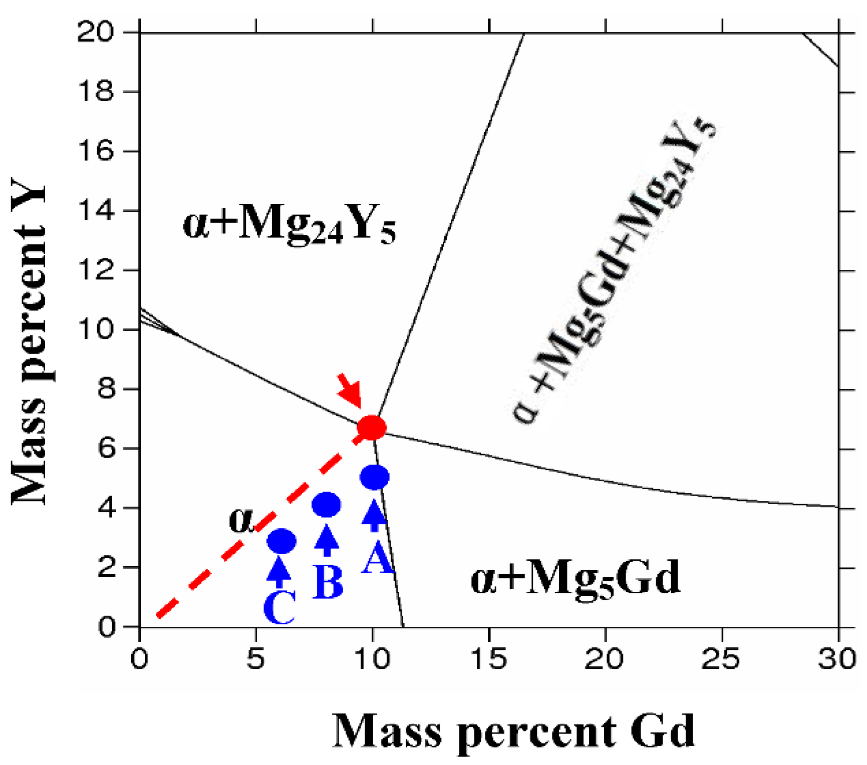
In order to determine the variation of solubility of Gd, Y elements in Mg, the Mg-Gd-Y-Nd phase diagram was calculated by Thermo-Calc software (TCW version 2, Thermo-Calc software, Stockholm, Sweden). According to the Mg-Nd binary phase diagram [12], element Nd has a low solubility in magnesium, so the content of Nd element was fixed to 1.0 wt% in this calculation. Moreover, in Mg-Gd-Y-Nd-Zr alloy, Zr plays the role of grain refining [21] and it was also not considered in this calculation. On the other hand, 520 °C is adopted for solution treatment in this paper, so the isothermal section at 520 °C was calculated. Figure 1 shows the calculated Mg-Gd-Y-Nd isothermal section at 1.0 wt% Nd at 520 °C. It indicates that maximum solubility of the alloying elements in magnesium is about 10.0 wt% Gd, 6.6 wt% Y, and 1.0 wt% Nd, as shown by the red arrow in Figure 1. Therefore, three compositions in the order of decreasing Gd and Y total contents were designed, as indicated by the blue dots labeled as A, B, and C in Figure 1.
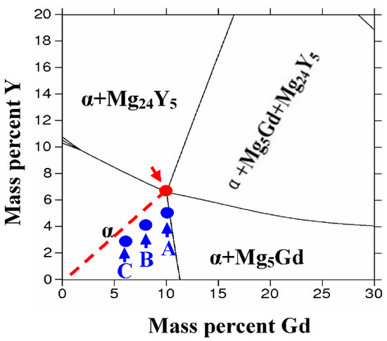
Figure 1.
Calculated Mg-Gd-Y-Nd isothermal section at 1.0 wt% Nd at 520 °C.
3. Materials and Methods
The ingots were prepared from Mg-Gd, Mg-Y, Mg-Nd, and Mg-Zr master alloys and high purity Mg. The raw materials were melted in a mild steel crucible at 760 °C under the protection of argon atmosphere. The actual chemical compositions of alloys A, B, and C are listed in Table 1. According to the phase diagrams [12] and other references [4,5], solution treatment and aging treatment were performed in a resistance furnace at 520 °C and 225 °C, respectively. Hardness measurement was taken using a 30 N load and holding time of 15 s. Dog-bone shaped samples with a diameter of 5 mm and a gauge length of 25 mm were prepared for tensile testing. Tensile testing was carried out on an 810 Material Test System (MTS Systems Corporation, Eden Prairie, MN, USA) with a crosshead speed of 1 mm/min. Samples with dimensions of 15 mm × 15 mm × 3 mm in as-cast and solution treated conditions for scanning electron microscopy (SEM) observation were prepared by mechanical grinding, polishing, and etching, and a solution of 4.0 vol% HNO3 with ethanol was prepared for etching, and the etching time was 20–30 s. SEM examination was performed in an FEI Quanta-200 (FEI, Eindhoven, The Netherlands) scanning electron microscope, and the chemical composition of the second phase in the alloy was analyzed using an equipped energy dispersive spectrometer (EDS). The SEM examination was carried out at an acceleration voltage of 20 kV. X-ray diffraction (XRD) studies were carried out on a Rigaku D/max2500 (Rigaku Corporation, Tokyo, Japan) diffractometer with Cu Kαradiation. The scanning speed was 7°/min with scanning angles ranging from 10° to 80°.

Table 1.
Chemical composition of the three designed alloys A, B, and C.
4. Results
4.1. Microstructure of the As-Cast Sample
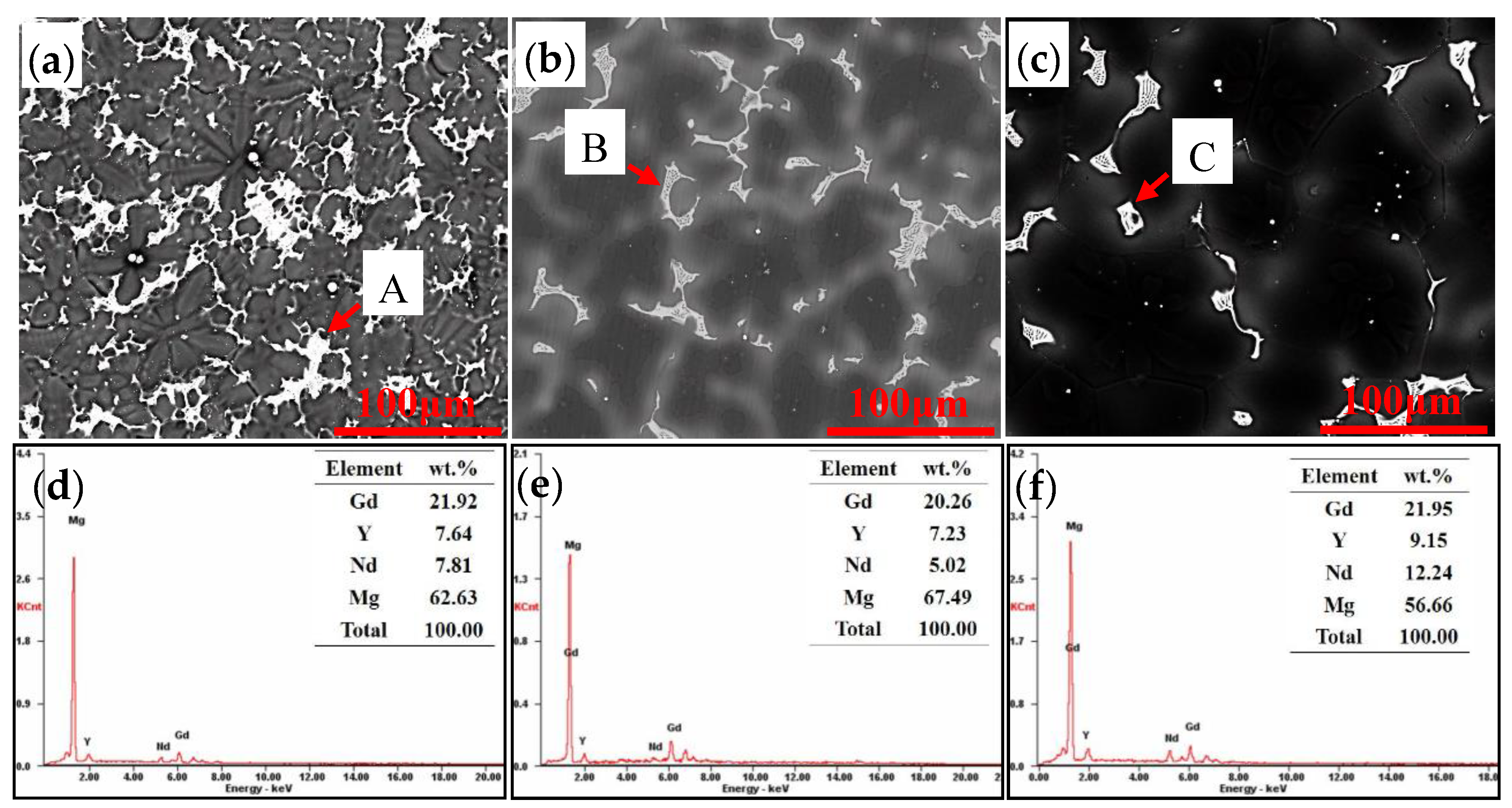
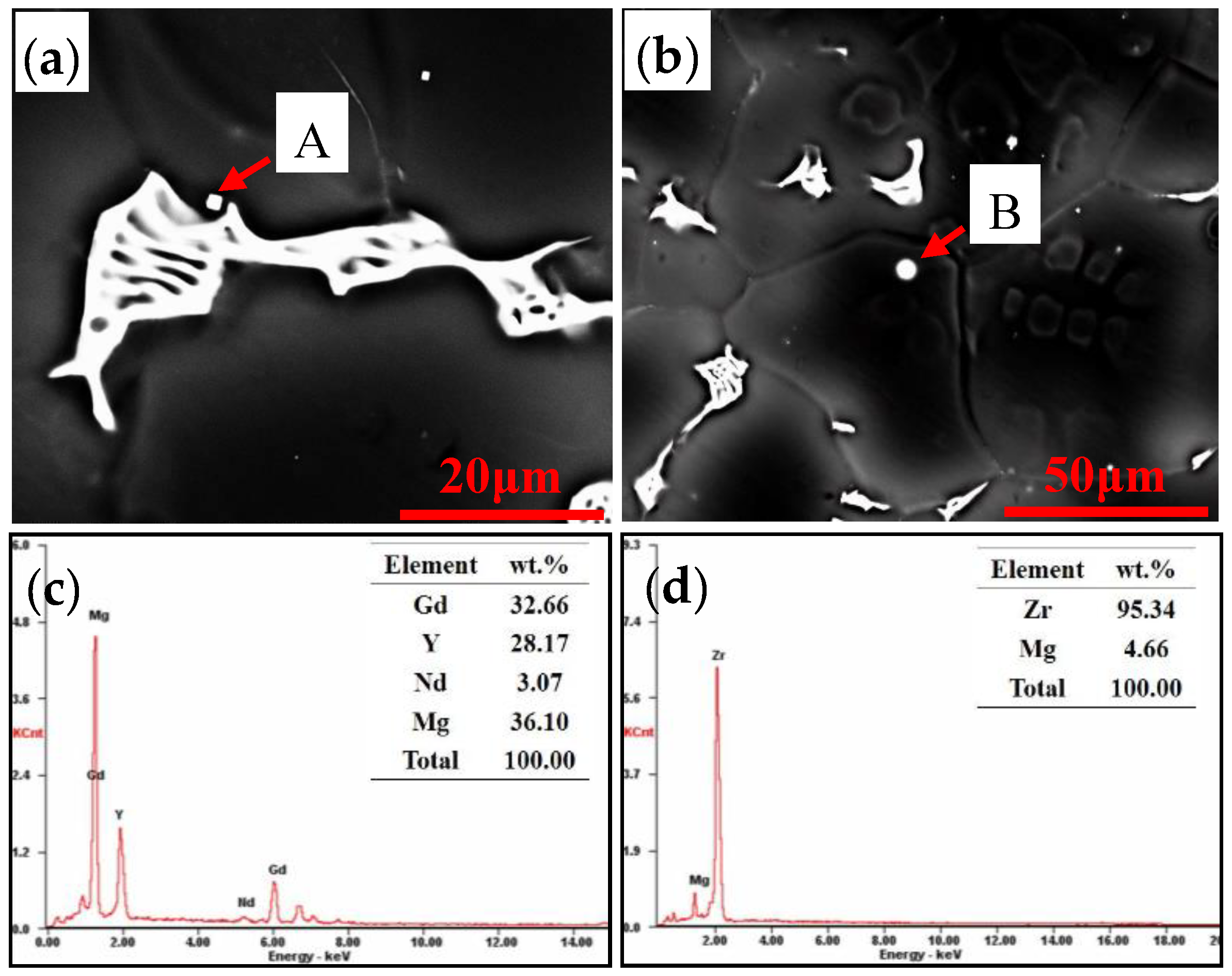
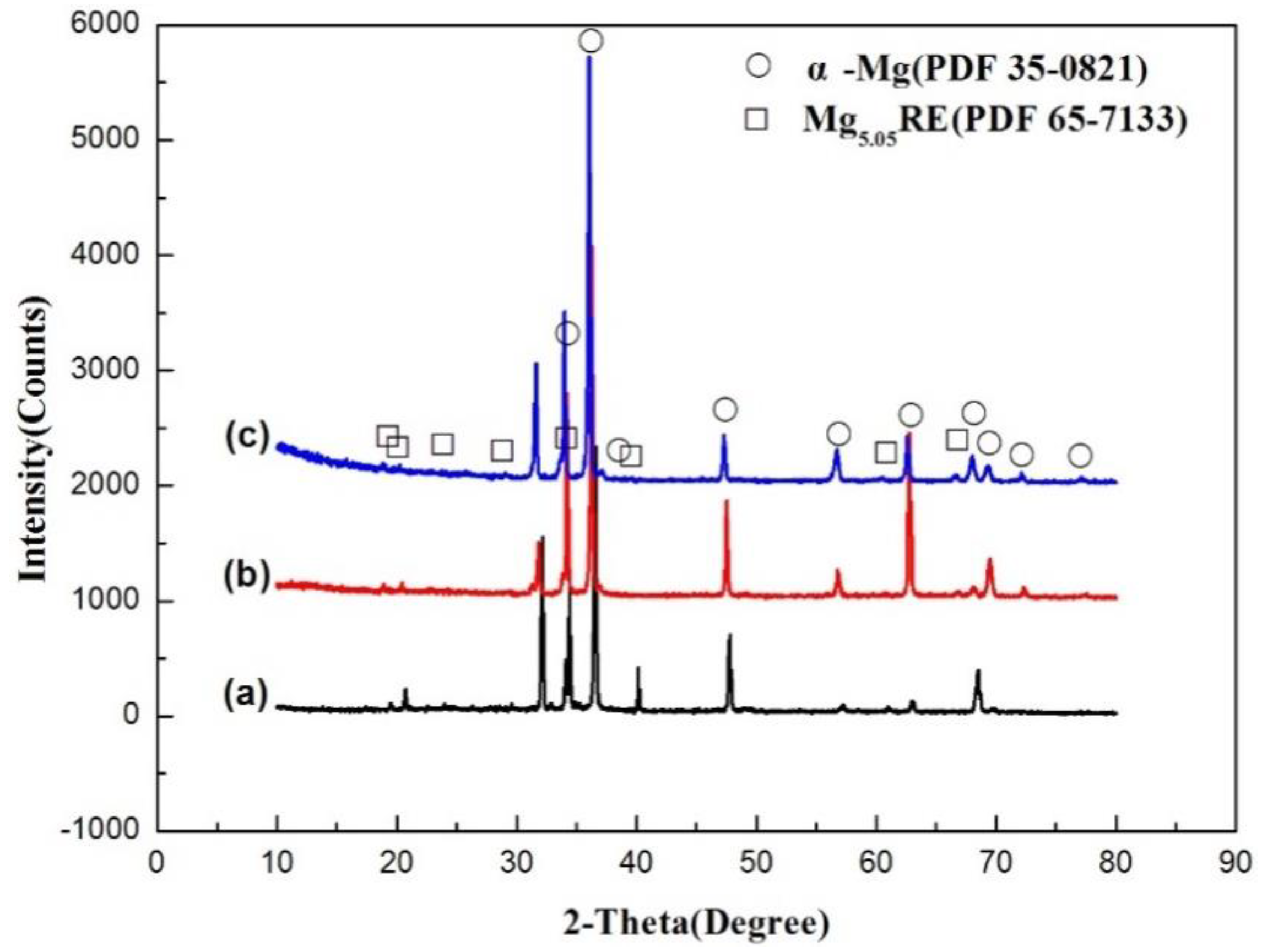
Figure 2 shows the SEM images of alloys A, B, and C in as-cast condition. A large number of white second phases are observed at the grain boundaries in all of the three alloys. Further detection revealed that they are black and white layered structures, as shown in Figure 3a, exhibiting the typical feature of a non-equilibrium eutectic. Formation of this type of structure is ascribed to the high cooling rate during solidification, which cannot satisfy the conditions of equilibrium solidification. The volume fractions of non-equilibrium eutectics in the three alloys decrease with decreasing Gd and Y content. EDS results shown in Figure 2 indicate that the non-equilibrium eutectic is rich in Gd, Y, and Nd elements. In order to determine the compositions of the non-equilibrium eutectics, Figure 4 shows the XRD patterns of the three alloys in as-cast condition. It is apparent that more diffraction peaks marked by “☐” are detected at 2θ = 34.0°, 20.6°, and 60.9° besides the diffraction peaks of α-Mg matrix. These peaks are consistent with the diffraction peaks of Mg5.05Gd (PDF 65-7133). Combined with the SEM images and the EDS results shown in Figure 2, these diffraction peaks are related to the non-equilibrium eutectic, and the Gd atoms in the non-equilibrium eutectic are partially replaced by Y and Nd atoms, as the radii of Gd, Y, Nd atoms are all very close. Therefore, the chemical composition of the non-equilibrium eutectic can be expressed as Mg5.05RE (RE = Gd, Y, Nd).
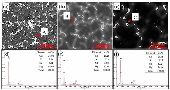
Figure 2.
Scanning electron microscopy (SEM) images and energy dispersive spectrometry (EDS) results of alloys with different Gd and Y contents: (a) SEM image of alloy A (b) SEM image of alloy B (c) SEM image of alloy C (d) EDS results of particle A(e) EDS results of particle B (f) EDS results of particle C.
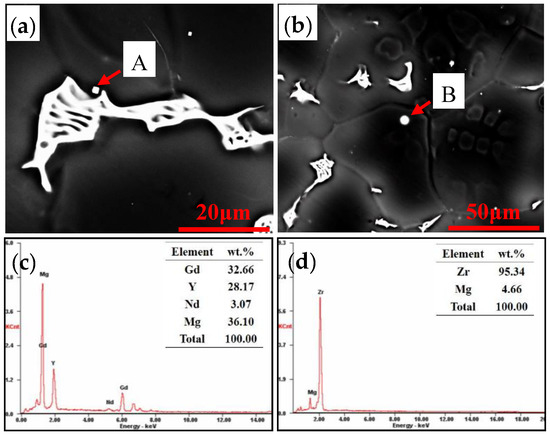
Figure 3.
Partial region feature of alloy C in as-cast condition: (a) The area containing block shaped particles. (b) The area containing spherical particles. (c) EDS results of particle A. (d) EDS results of particle B.

Figure 4.
X-ray diffraction (XRD) spectra of the as-cast alloys: (a) Alloy A, (b) Alloy B, (c) Alloy C.
A small number of white block shaped particles was also observed near the non-equilibrium eutectic, as indicated by arrow A in Figure 3a. The EDS results of the particle (Figure 3c) show that it is rich in rare earth elements, including Gd content of 32.66 wt%, Y content of 28.17 wt%, and Nd content of 3.07 wt%. Comparing the EDS results of the block shaped particle (Figure 3c) with that of the non-equilibrium eutectics (Figure 2), it was found that they are all rich in rare earth elements, but the contents of Gd and Y in the block shaped particles are higher than that in the non-equilibrium eutectic, while the content of Nd is lower than that in the non-equilibrium eutectic. White spherical particles are also observed besides the non-equilibrium eutectic and white block shaped particles, as indicated by arrow B in Figure 3b. The EDS results indicate that it is a Zr-rich (Figure 3d) particle. The spherical particles are formed by a peritectic reaction during solidification, and then act as a nucleus for grain refining. Peng et al. [21] investigated the grain refining mechanism of Zr in as-cast alloy, and the results indicated that Zr mainly restricts grain growth in low Zr content (0.25 wt%) alloys, and Zr provides nuclei for high Zr content (0.40 wt% and 0.51 wt%) alloys. Obviously, in alloys A, B, and C, grain refining is achieved through generation of nuclei caused by Zr addition.
4.2. Microstructure of the Solution Treated Alloys
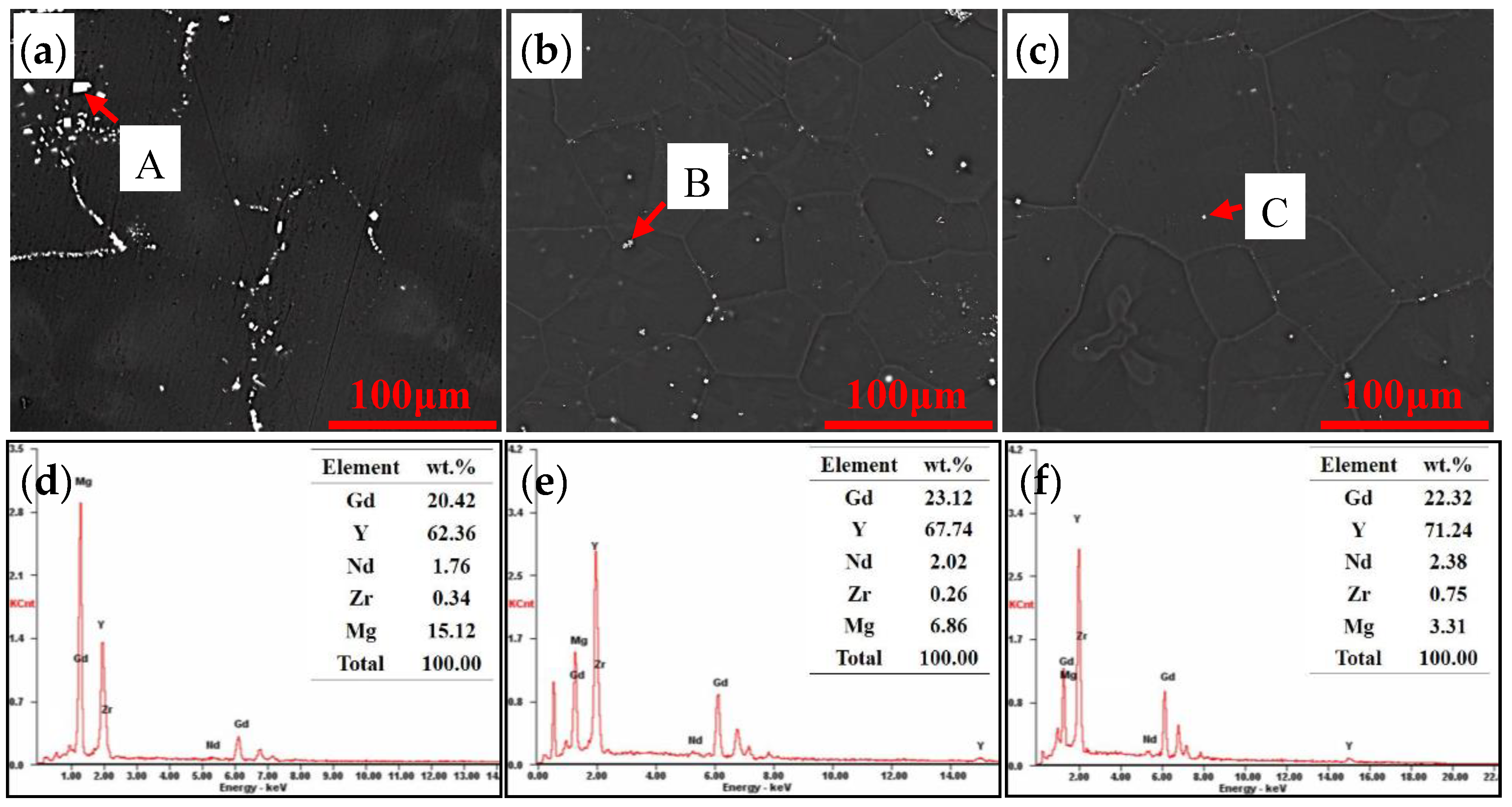
In order to form a supersaturated solid solution, solution treatment was adopted to dissolve the non-equilibrium eutectics. Figure 5 shows the SEM images of the alloys after solution treatment. A large number of agglomerated block shaped white particles are observed in alloy A. The EDS results (Figure 5d) show that the white particles are rich in rare earth elements, including Gd content of 20.42 wt%, Y content of 62.36 wt%, and Nd content of 1.76 wt%. The quantity of the block shaped particles at the grain boundaries decrease as the total content of Gd and Y decreases. The numbert of particles at the grain boundaries is decreased to a lower level in alloy C. The chemical compositions of the block shaped particles remain stable (Figure 5d–f), and there is no significant fluctuation in composition when the Gd and Y contents vary in the alloys. The slight differences in values of EDS results may be caused by the error of the energy dispersive spectrometer.
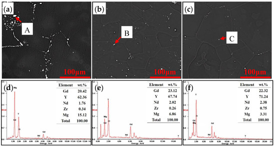
Figure 5.
SEM images and EDS results of the solution treated samples: (a) SEM image of alloy A, (b) SEM image of alloy B, (c) SEM image of alloy C, (d) EDS results of particle A, (e) EDS results of particle B, (f) EDS results of particle C.
4.3. Mechanical Properties
The aging curves of alloys A, B, and C at 225 °C are shown in Figure 6. The aging curves of the three alloys share similar features except aging kinetics and peak hardness. At the initial stage of aging, the hardness of the alloy increases rapidly with the aging time. After reaching peak hardness, the hardness slowly declines with increasing aging time, presenting peak platforms that are usually found in Mg-Gd-based alloys. This reveals that all of the three alloys exhibit remarkable age hardening behavior, while the peak hardness decreases with decreasing total content of Gd and Y elements.
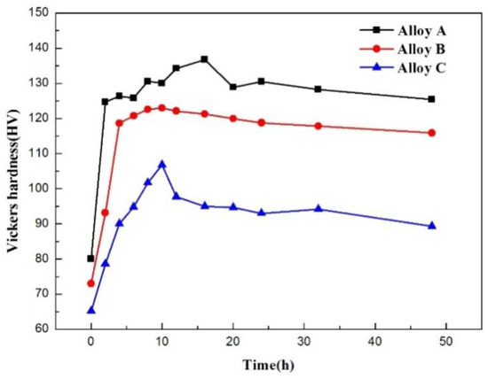
Figure 6.
Aging curves of alloys A, B, and C at 225 °C.
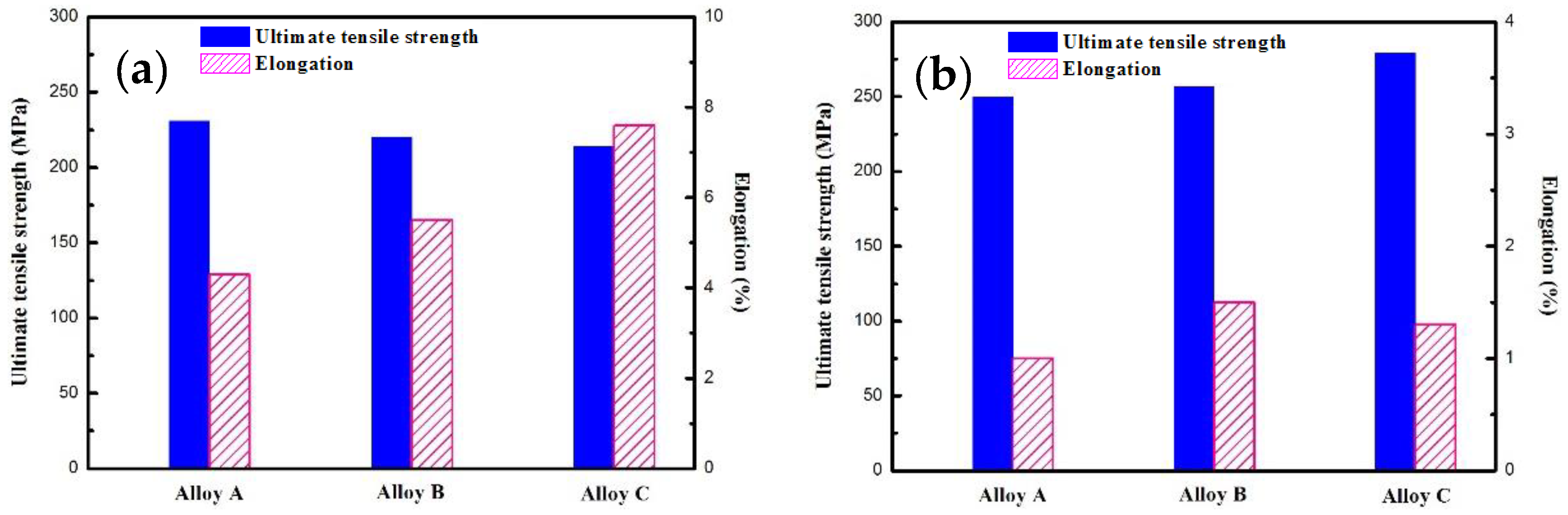
In order to obtain the strength and elongation of the alloys, uniaxial tensile tests were carried out on the alloys with different tempers. The mechanical properties containing the ultimate tensile strength and elongation of alloys A, B, and C are shown in Figure 7. The ultimate tensile strength and elongation of alloy A in solution treated conditions are 231 MPa and 4.3%, respectively. The ultimate tensile strength decreases slightly with decreasing total content of Gd and Y, while the elongation increases with decreasing total content of Gd and Y. When the total content of Gd and Y decreases to about 9 wt% (alloy C), the ultimate tensile strength is 214 MPa, which is 7.4% lower than that of alloy A, and the elongation is 7.6%, which is 76.7% higher than that of alloy A. However, after aging treatment, the trend of strength variation is opposite to that of the solution treated samples. The ultimate tensile strength increases with decreasing total content of Gd and Y, which is also opposite to the peak hardness variation trend shown in Figure 6. As mentioned above, the non-equilibrium eutectics at the grain boundaries are dissolved into the matrix in the solution treated condition, which leads to a higher solid solution strengthening effect and a higher ultimate tensile strength in the alloys containing more Gd and Y content. Therefore, the ultimate tensile strength decreases with the order of alloys A, B, and C. Similarly, the more the Gd and Y atoms dissolve into the matrix, the greater the precipitates formed during aging. So the peak hardness shows the same variation trend with that of ultimate tensile strength of solution treated samples. However, as shown in Figure 5, the amount of block shaped particles at the grain boundaries increases with increasing Gd, and Y content. The decrease in ultimate tensile strength after aging may be related to the second phases, which may deteriorate the mechanical properties when the sample is subjected to tensile stress. Although there are also block shaped particles in the solution treated samples, due to the absence of precipitates in the grains, the deformation capacity of the grains is higher than that of the T6 treated sample, which may release the stress concentration caused by the second phase particles at the grain boundaries and decrease the harmful effects of the second phase at the grain boundaries.

Figure 7.
Room temperature tensile results of the alloys with different tempers: (a) Solution treated condition, (b) T6.
5. Discussion
5.1. Formation Process of the Block Shaped Particles
Based on the results mentioned above, it was found that the block shaped particle had already appeared in the as-cast sample as shown by arrow A in Figure 3a. However, comparing the EDS results (Figure 3c) with that of the block shaped particles in solution treated samples shown in Figure 5d–f, the compositions are quite different despite the particles having the same morphology. The block shaped particles in the as-cast condition are mainly rich in Gd and Y, and the mass fraction of Gd is higher than that of Y, while the content of Nd is only slightly higher than that of the matrix. Nevertheless, after solution treatment, the particles mainly contain Y, and the mass fraction of Y ranges from 60 wt% to 70 wt%, while the content of Gd element is decreased compared with that of the particle in the as-cast sample, but the content of Nd remains stable. Therefore, the results indicate that solute atom migration occurs between the formed block shaped particles in the as-cast state and the matrix during solution treatment. In addition, it was found that the number of block shaped particles increases significantly after solution treatment by comparing the SEM images of the solution treated samples (Figure 5) with that of the as-cast samples (Figure 2), which indicates new block shaped particles are formed during solution treatment. After solution treatment, compared with the EDS results (Figure 2d–f) of the non-equilibrium eutectic, the content of Y in the block shaped particles (Figure 5d–f) increases significantly, the content of Gd remains stable, and the content of Nd decreases significantly. Therefore, the block shaped particles in the solution treated samples arise from two parts. One part is formed during the solidification and then the composition changes during the solution treatment, while the other part is formed during the dissolution process of the non-equilibrium eutectics.
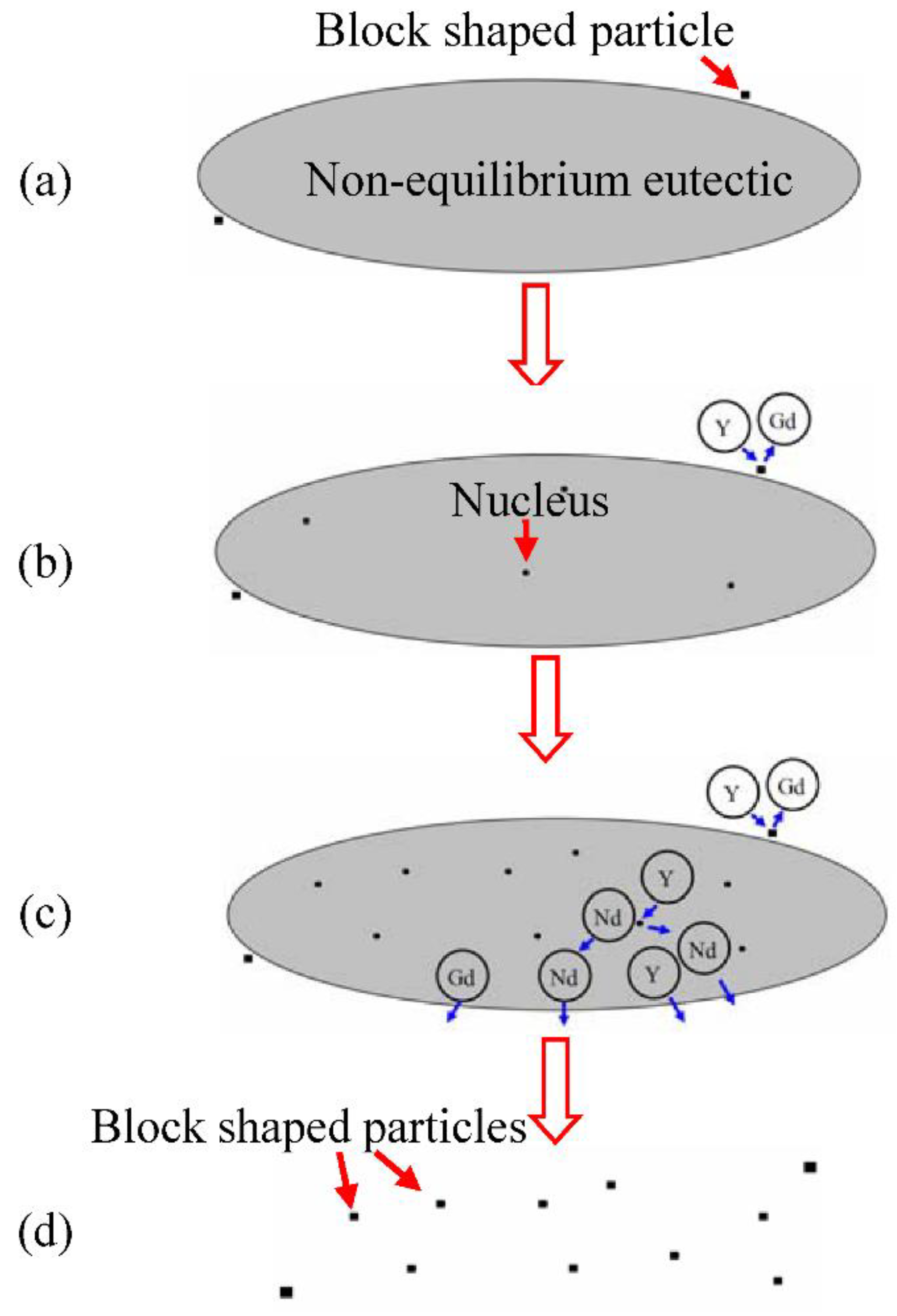
The migration process of the solute atoms during the formation of the block shaped particles can be represented by a schematic diagram as shown in Figure 8 according to the analysis mentioned above. The Gd atoms in the particle formed during solidification dissolve into the matrix, and the Y atoms aggregate from the matrix to the block shaped particle, leading to the formation of particles with high Y content (Figure 8b). In the non-equilibrium eutectic, it can be inferred that the formation of block shaped particles inevitably experiences the process of nucleation and growth according to the principle of phase transformation. First, due to the composition fluctuation, the nuclei are formed in the micro-areas with high Y content, as shown in Figure 8b. Then, Nd atoms partially diffuse into the non-equilibrium eutectic and Y atoms diffuse toward the nuclei, which leads to nuclei growth. Simultaneously, other nuclei form in other micro-areas of the non-equilibrium eutectics. Finally, the non-equilibrium eutectics dissolve into the matrix and the block shaped particles are left in the sample, as shown in Figure 8d.

Figure 8.
Schematic diagram of the generation process of block shaped particles: (a) As-cast condition, (b) Composition variation of the particle formed at as-cast condition, (c) Particle formation process in the non-equilibrium eutectic, (d) Solution treated condition.
5.2. Effects of Second Phases on Fracture
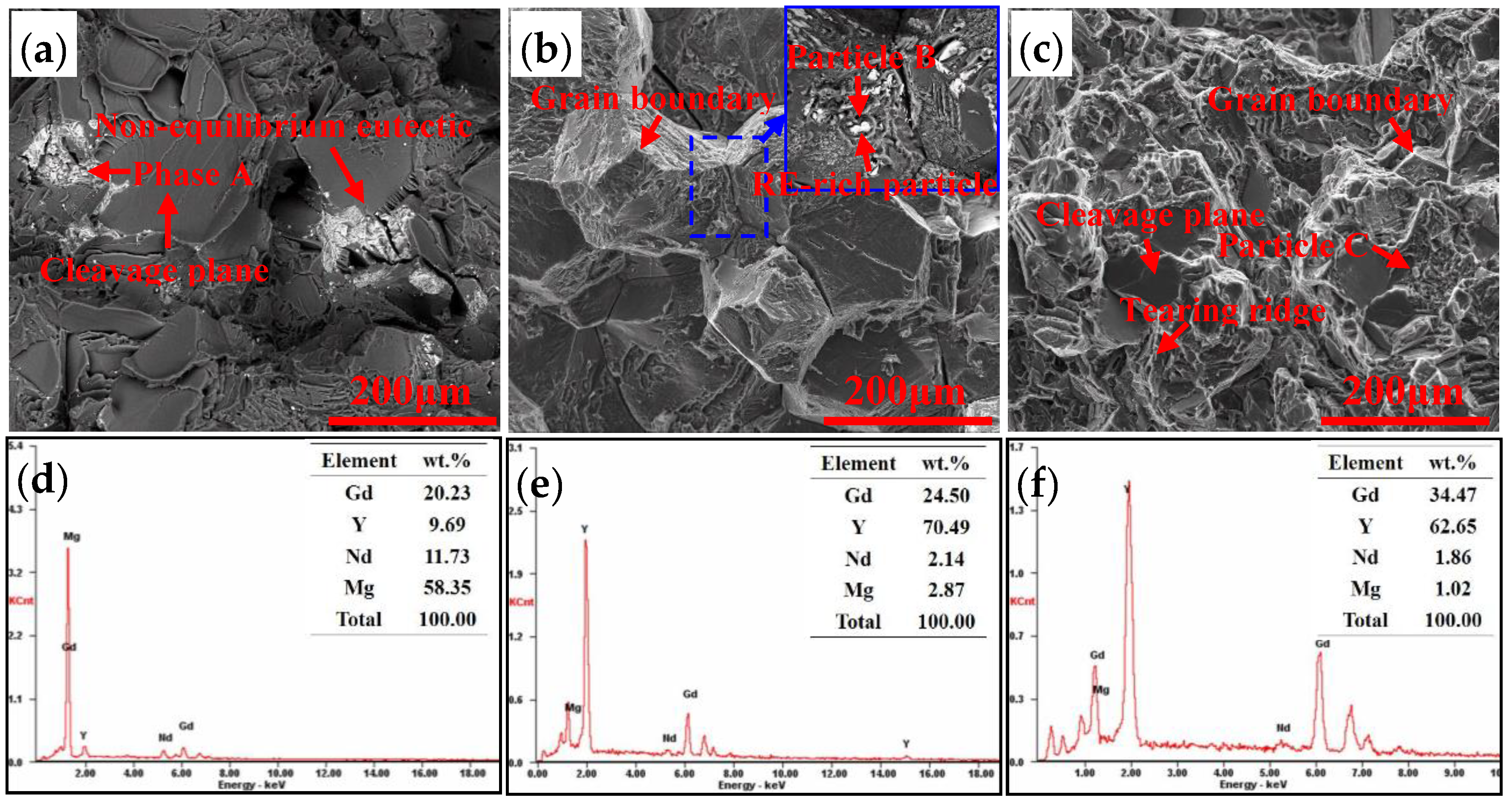
In order to understand the fracture mechanism of the alloy, the fracture surfaces of the samples were analyzed. Figure 9 shows SEM images and EDS results of the tensile fracture surfaces of alloys A, B, and C with T6 temper. It indicates that the fracture morphology significantly altered with the decreasing of Gd, Y content. A large number of cleavage planes are observed in the fracture surface of alloy A. A small amount of second phases is also found in some regions.EDS results shown in Figure 9d indicate that they are non-equilibrium eutectics, illustrating that part of the eutectics cannot dissolve into the matrix. According to the phase diagram (Figure 1), it was found that the composition of alloy A is close to the maximum solubility of Mg-Gd-Y-Nd alloys. After solution treatment, in most regions, the non-equilibrium eutectics dissolve into the matrix, as shown in Figure 5a. However, since inhomogeneous composition distribution in the ingot is inevitable, the compositions in some areas may be too high to dissolve all the non-equilibrium eutectics. Because of the large sizes, the residual non-equilibrium eutectics are liable to cause stress concentration and stimulate cleavage fracture, which deteriorates the mechanical properties of the alloy. As the total content of Gd and Y decreases, a large number of grain boundaries are observed in the fracture surface of alloy B, as shown by the arrow in Figure 9b, exhibiting a typical feature of intergranular fracture. A large number of block shaped particles are distributed on the grain boundaries, as indicated by the arrow in the backscattered electron diffraction image shown in the upper right corner of Figure 9b, indicating that the particles greatly weaken the strength of the grain boundary and lead to intergranular fracture in alloy B. EDS results shown in Figure 9e indicate that it is consistent with the residual particles after solution treatment. In the fracture surface of alloy C, there is exhibited a mixed fracture mode containing transgranular fracture and intergranular fracture. Plenty of cleavage planes, grain boundaries, and tearing ridges are observed in the fracture surface, and a small amount of particles (Figure 9f) is observed. As mentioned above, with the increase of Gd and Y content, more solute atoms dissolve in the matrix, which leads to a higher peak hardness. However, the higher Gd, Y content also results in the increase of block shaped particles and the residual non-equilibrium eutectics at the grain boundaries, which tends to cause stress concentration and deteriorate the tensile strength. On the other hand, the grain sizes of alloys A (104 μm) and B (124 μm) are much coarser than that of alloy C (66 μm), which can also decrease the grain boundary strengthening effect of alloys A and B. Therefore, the highest ultimate tensile strength is obtained in alloy C with T6 temper. The high strength is attributed to the decrease in block shaped particles at the grain boundaries and the age hardening behavior. The ultimate tensile strength of alloy C in T6 temper is equivalent to that of Electron WE54 alloy [22], whose total rare earth content is similar to alloy C. Compared with Electron 21, alloy C exhibits a higher ultimate tensile strength [23].
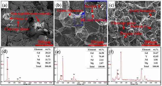
Figure 9.
SEM images and EDS results of the fracture surfaces of alloys with different Gd, Y contents: (a) SEM image of alloy A (b) SEM images of alloy B (c) SEM image of alloy C (d) EDS results of phase A (e) EDS results of particle B (f) EDS results of particle C.
6. Conclusions
- (1)
- The as-cast ingots of the three alloys are mainly composed of α-Mg and non-equilibrium eutectic Mg5.05RE. The total contents of Gd and Y have no significant effect on the phase composition of the as-cast alloy.
- (2)
- The non-equilibrium eutectics are able to dissolve into the matrix when solution treated at 520 °C, but block shaped particles are left at the grain boundaries and within grains. The particles are RE-rich especially rich in Y element, and the compositions of the particles are independent of the total Gd and Y contents of the alloys while the quantity increases on increasing the total Gd and Y content.
- (3)
- The ultimate tensile strength of the solution treated samples increases as the Gd, Y content increases, while the ultimate tensile strength of the T6 treated samples decreases with increasing Gd, Y content. The increasing strength in solution treated samples is attributed to solid solution strengthening and excellent deformation capacity of the grains, and the decreasing strength in the T6 treated samples is ascribed to the increasing number of block shaped particles and the residual non-equilibrium eutectics, which deteriorate the mechanical properties.
- (4)
- The Mg-5.56Gd-3.38Y-1.11Nd-0.48Zr alloy exhibits the highest strength. The ultimate tensile strength and elongation of the alloy with T6 temper are 280 MPa and 1.3%, respectively. The high strength is attributed to the age hardening behavior and the decrease in block shaped particles.
Author Contributions
Conceptualization, C.T. and W.L.; Formal analysis, C.T. and D.F.; Investigation, C.T., K.W., X.W., G.M., and M.Y.; Writing—original draft, C.T.; Writing—review & editing, X.L. and Q.L.
Funding
This research was funded byNational Natural Science Foundation of China (Grant Nos. 51605159 and 51601062), Hunan Provincial Natural Science Foundation of China (Grant No. 2016JJ5042) and National Magnesium program (Grant No. 41422010705).
Acknowledgments
The authors would like to appreciate the financial supports from National Natural Science Foundation of China (Grant Nos. 51605159 and 51601062), Hunan Provincial Natural Science Foundation of China (Grant No. 2016JJ5042) and National Magnesium program (Grant No. 41422010705). The authors also would like to appreciate Liqun Guan of Central South University for the help of phase diagram calculation.
Conflicts of Interest
The authors declare no conflict of interest.
References
- Mordike, B.L.; Ebert, T. Magnesium: Properties—Applications—Potential. Mater. Sci. Eng. A 2001, 302, 37–45. [Google Scholar] [CrossRef]
- Dharmendra, C.; Rao, K.P.; Suresh, K.; Hort, N. Hot deformation behavior and processing map of Mg-3Sn-2Ca-0.4Al-0.4Zn alloy. Metals 2018, 8, 216. [Google Scholar] [CrossRef]
- Liu, H.; Huang, H.; Wang, C.; Ju, J.; Sun, J.P.; Wu, Y.N.; Jiang, J.H.; Ma, A.B. Comparative study of two aging treatments on microstructure and mechanical properties of an ultra-finegrained Mg-10Y-6Gd-1.5Zn-0.5Zr alloy. Metals 2018, 8, 658. [Google Scholar] [CrossRef]
- Saboori, A.; Padovano, E.; Pavese, M.; Dieringa, H.; Badini, C. Effect of solution treatment on precipitation behaviors, age hardening response and creep properties of Elektron21 alloy reinforced by AlN nanoparticles. Materials 2017, 10, 1380. [Google Scholar] [CrossRef] [PubMed]
- Saboori, A.; Padovano, E.; Pavese, M.; Badini, C. Novel magnesium Elektron21-AlN nanocomposites produced by ultrasound-assisted casting; microstructure, thermal and electrical conductivity. Materials 2018, 11, 27. [Google Scholar] [CrossRef] [PubMed]
- He, S.M.; Zeng, X.Q.; Peng, L.M.; Gao, X.; Nie, J.F.; Ding, W.J. Precipitation in a Mg-10Gd-3Y-0.4Zr (wt.%) alloy during isothermal ageing at 250 °C. J. Alloys Compd. 2006, 421, 309–313. [Google Scholar] [CrossRef]
- He, S.M.; Zeng, X.Q.; Peng, L.M.; Gao, X.; Nie, J.F.; Ding, W.J. Microstructure and strengthening mechanism of high strength Mg-10Gd-2Y-0.5Zr alloy. J. Alloys Compd. 2007, 427, 316–323. [Google Scholar] [CrossRef]
- Wang, Q.D.; Chen, J.; Zhao, Z.; He, S.M. Microstructure and super high strength of cast Mg-8.5Gd-2.3Y-1.8Ag-0.4Zr alloy. Mater. Sci. Eng. A 2010, 528, 323–328. [Google Scholar] [CrossRef]
- Jiang, L.K.; Liu, W.C.; Wu, G.H.; Ding, W.J. Effect of chemical composition on the microstructure, tensile properties and fatigue behavior of sand-cast Mg-Gd-Y-Zr alloy. Mater. Sci. Eng. A 2014, 612, 293–301. [Google Scholar] [CrossRef]
- Nodooshan, H.R.J.; Liu, W.C.; Wu, G.H.; Rao, Y.; Zhou, C.X.; He, S.P.; Ding, W.J.; Mahmudi, R. Effect of Gd content on microstructure and mechanical properties of Mg-Gd-Y-Zr alloys under peak-aged condition. Mater. Sci. Eng. A 2014, 615, 79–86. [Google Scholar] [CrossRef]
- Tekumalla, S.; Seetharaman, S.; Almajid, A.; Gupta, M. Mechanical properties of magnesium-rare earth alloy systems: A review. Metals 2015, 5, 1–39. [Google Scholar] [CrossRef]
- Rokhlin, L.L. Magnesium Alloys Containing Rare Earth Metals: Structure and Properties, 1st ed.; Taylor & Francis: London, UK, 2003; pp. 32–45. [Google Scholar]
- Zhang, Y.; Wu, Y.J.; Peng, L.M.; Fu, P.H.; Huang, F.; Ding, W.J. Microstructure evolution and mechanical properties of an ultra-high strength casting Mg-15.6Gd-1.8Ag-0.4Zr alloy. J. Alloys Compd. 2014, 615, 703–711. [Google Scholar] [CrossRef]
- Honma, T.; Ohkubo, T.; Kamado, S.; Hono, K. Effect of Zn additions on the age-hardening of Mg-2.0Gd-1.2Y-0.2Zr alloys. Acta Mater. 2007, 55, 4137–4150. [Google Scholar] [CrossRef]
- Peng, Q.M.; Wang, J.L.; Wu, Y.M.; Meng, J.; Wang, L.M. The effect of La or Ce on ageing response and mechanical properties of cast Mg-Gd-Zr alloys. Mater. Charact. 2008, 59, 435–439. [Google Scholar] [CrossRef]
- Peng, Q.M.; Wang, L.D.; Wu, Y.M.; Wang, L.M. Structure stability and strengthening mechanism of die-cast Mg-Gd-Dy based alloy. J. Alloys Compd. 2009, 469, 587–592. [Google Scholar] [CrossRef]
- Dai, J.C.; Zhu, S.M.; Easton, M.A.; Zhang, M.X.; Qiu, D.; Wu, G.H.; Liu, W.C.; Ding, W.J. Heat treatment, microstructure and mechanical properties of a Mg-Gd-Y alloy grain-refined by Al additions. Mater. Sci. Eng. A 2013, 576, 298–305. [Google Scholar] [CrossRef]
- Zhang, X.G.; Meng, L.G.; Fang, C.F.; Peng, P.; Ja, F.; Hao, H. Effect of Nd on the microstructure and mechanical properties of Mg-8Gd-5Y-2Zn-0.5Zr alloy. Mater. Sci. Eng. A 2013, 586, 19–24. [Google Scholar] [CrossRef]
- Zhang, L.; Gong, M.; Peng, L.M. Microstructure and strengthening mechanism of a thermomechanically treated Mg-10Gd-3Y-1Sn-0.5Zr alloy. Mater. Sci. Eng. A 2013, 565, 262–268. [Google Scholar] [CrossRef]
- Fang, C.F.; Liu, G.X.; Hao, H.; Wen, Z.H.; Zhang, X.G. Effect of Al addition on microstructure, texture and mechanical properties of Mg-5Gd-2.5Y-2Zn alloy. J. Alloys Compd. 2016, 686, 347–355. [Google Scholar] [CrossRef]
- Peng, Z.K.; Zhang, X.M.; Chen, J.M.; Xiao, Y.; Jiang, H. Grain refining mechanism in Mg-9Gd-4Y alloys by zirconium. Mater. Sci. Technol. 2005, 21, 722–726. [Google Scholar] [CrossRef]
- Magnesium Elektron: Service and Innovation in Magnesium. Available online: https://www.magnesium-elektron.com/wp-content/uploads/2016/10/Elektron-WE54_0.pdf (accessed on 31 August 2018).
- Magnesium Elektron: Service and Innovation in Magnesium. Available online: https://www.magnesium-elektron.com/wp-content/uploads/2017/05/Elektron-21.pdf (accessed on 23 September 2018).

© 2018 by the authors. Licensee MDPI, Basel, Switzerland. This article is an open access article distributed under the terms and conditions of the Creative Commons Attribution (CC BY) license (http://creativecommons.org/licenses/by/4.0/).