Article

Microstructure and Mechanical Properties of Heat-Affected Zone of Repeated Welding AISI 304N Austenitic Stainless Steel by Gleeble Simulator

1
School of Materials Science and Engineering, Dalian University of Technology, Dalian 116024, China
2
China Nuclear Industry 23 Construction Co., Ltd., Beijing 101300, China
*
Author to whom correspondence should be addressed.
Metals 2018, 8(10), 773; https://doi.org/10.3390/met8100773
Submission received: 6 August 2018 / Revised: 22 September 2018 / Accepted: 26 September 2018 / Published: 27 September 2018

Abstract

:
Heat-affected zone (HAZ) of welding joints critical to the equipment safety service are commonly repeatedly welded in industries. Thus, the effects of repeated welding up to six times on the microstructure and mechanical properties of HAZ for AISI 304N austenitic stainless steel specimens were investigated by a Gleeble simulator. The temperature field of HAZ was measured by in situ thermocouples. The as-welded and one to five times repeated welding were assigned as-welded (AW) and repeated welding 1–5 times (RW1–RW5), respectively. The austenitic matrices with the δ-ferrite were observed in all specimens by the metallography. The δ-ferrite content was also determined using magnetic and metallography methods. The δ-ferrite had a lathy structure with a content of 0.69–3.13 vol.%. The austenitic grains were equiaxial with an average size of 41.4–47.3 μm. The ultimate tensile strength (UTS) and yield strength (YS) mainly depended on the δ-ferrite content; otherwise, the impact energy mainly depended on both the austenitic grain size and the δ-ferrite content. The UTS of the RW1–RW3 specimens was above 550 MPa following the American Society of Mechanical Engineers (ASME) standard. The impact energy of all specimens was higher than that in ASME standard at about 56 J. The repeated welding up to three times could still meet the requirements for strength and toughness of welding specifications.

Graphical Abstract

1. Introduction

Repeated welding in the same location is a necessary process for construction, maintenance, and repair in industrial sectors. However, the repeated welding regulations in different standards are not the same. According to the GB50236 3.0.6 clause for pipelines [1], welding seams should not be repaired more than twice in the same location. In the IPS-C-PI-270(2) [2], it is expressed that a weld with unacceptable defects may be repaired only once. In the RCC-M IV Welding S7610 for nuclear power plants [3], it requires that two welding repairs may be performed at the same location. While in ASME BPVC III NB [4], the number of repeated welding is not limited, but the technical requirements for defect removal have been described in details.
AISI 304N austenitic stainless steel is widely used throughout nuclear equipment manufacture and construction due to good mechanical properties and adequate weldability. Due to aging and degradation for a long period of time at high temperatures and high pressure in nuclear power plant, some equipment needs maintenance and repair by the in situ welding method [5]. For example, the reactor coolant pump (RCP) of the nuclear plant requires an inspection at least five times and maintenance for the inner components during the service life. A sealing welding joint of the RCP must be opened and re-welded five times at the same location because of the structure design requirements. Multiple welding maintenances may change the microstructure and mechanical properties of the weld joints, especially the HAZ of weld joints. Therefore, it is necessary to investigate the microstructure and mechanical properties of the HAZ to evaluate the limitation number of the repeated welding. While the microstructure and mechanical properties of the repeated welding on austenitic stainless steels have been extensively investigated, no clear relationship and mechanism have been reached up until now. AghaAli et al. [6] studied the effects of one to four times the repeated welding on the microstructure and mechanical properties for AISI 316L stainless steel by shield metal arc welding (SMAW). With the increasing number of repeated welding, the grain recrystallization refinement of HAZ occurred due to cumulative welding heat input. The impact energy of the repeated welding joints monotonically decreased from 258 J of the as-welded specimens to 247 J of fourth repeated welding specimens. The mechanical properties of four times of the repeated welding joints could meet the requirements in a chloride-free environment [6]. The δ-ferrite in the HAZ of AISI 304L stainless steel of one and five times of the repeated welding by gas tungsten arc welding (GTAW) and SMAW changed to narrow and short lath accompanied by diffusion of the filler metal elements. The distribution frequency of the low angle grain boundaries decreased due to the welding heat input. There was no obvious difference between one and five times of the repeated welding joints in the impact energy, whereas the fracture features changed from brittle to ductile [7]. With the increasing number of one to four times repeated welding by SMAW for API 5L X85 micro-alloy steel, the coarse grains of HAZ recrystallized and then grew up. The impact energy of the repeated welding joints decreased from 120 J to 82 J. The tensile strength increased under the change in grain size owing to the welding heat input. After four times of repeated welding, the tensile strength and impact energy could meet the requirements of the standards [8]. With the times of the repeated welding of AISI 4130 martensitic stainless steel by a single bead GTAW, the grain size increased, and the angle and radius of the welding toe also increased. The axial fatigue strength of one to three times the repeated welding joints decreased and then increased. In the study, the axial fatigue strength of the repeated welding joints was largely affected by the microstructure and radius of the weld toe [9]. The controversial explanation of the relationship between the microstructure and mechanical properties could have resulted from the instability in manual welding and the very narrow region of the HAZ in the repeated welding joints [10].
The microstructure and mechanical properties of HAZ can be altered after experiencing thermal cycles imposed by the welding process. Many studies have shown that the degradation in strength and toughness always happens in HAZ. The Gleeble weld-simulator has been successfully employed to accurately control the thermal cycles and heat input to easily generate an available HAZ for the evaluation of the microstructure and mechanical properties [10,11,12]. Hsieh et al. [13] used Gleeble to precisely control the cooling time of the HAZ, and studied the effects of different cooling time on the microstructure of 22% Cr duplex stainless steel. This is difficult using traditional welding methods. Silwal et al. [14] investigated the toughness of coarse grain HAZ (CGHAZ) for Grade P91 steel under postweld heat treatment using a Gleeble weld-simulator. Using this method, a large volume of CGHAZ was obtained, and the effect of the post heat treatment on the toughness of the CGHAZ could be studied accurately. Therefore, the Gleeble simulation can be considered as an effective way to investigate the HAZ of the repeated welding with repeatability and reliability due to the controllable heat input over an area which is sufficient for following tensile and impact testing.
In this paper, a Gleeble weld-simulator was used to simulate one to five times repeated welding to study the microstructure and mechanical properties of the HAZ formed on AISI 304N austenitic stainless steel multi-bead welded specimens. The welding thermal cycles of multi-bead for simulations were measured experimentally by in situ thermocouples. The collected multi-bead welding thermal cycles were used as control heat input to prepare the as-welded and repeated welding HAZ specimens. The Gleeble weld-simulator specimens were subsequently used to examine the microstructure, grain size, δ-ferrite content, grain boundary character distribution, and tensile and impact properties to investigate the repeated welding effect on the microstructure and mechanical properties of the HAZ of AISI 304N austenitic stainless steel.

2. Materials and Methods

An AISI 304N austenitic stainless steel welding plate with a size of 240 mm × 150 mm × 20 mm was used in the multi-bead welding. The chemical composition and mechanical properties of AISI 304N austenitic stainless steel are listed in Table 1. Welding was performed using the GTAW process with ER308L filler wire of 2.0 mm in diameter by a Liburdi GT VI machine (Liburdi, Ontario, ON, Canada) with automatic arc voltage tracking. A 60° beveled groove with a depth of 10 mm was machined in the center of the welding plate. Figure 1 shows the V-groove joint and welding schedule. The welding process parameters are listed in Table 2. The welding process was the same as that performed in commercial welding and consisted of seven beads, designated with L1–L7 in sequence. Figure 2 shows the experimental system for the measurement of welding thermal cycles, which is composed of three parts: Auto-welding GTAW machine, temperature logger, and thermocouples. A 20-channel temperature logger by Fluke NetDAQ (Fluke Calibration, Everett, MA, USA) was used to record the temperature field with a sampling frequency of 60 Hz. Figure 3 shows the arrangement of the K-type thermocouple with a thermocouple wire diameter of 0.1 mm. All thermocouples, which were grouped into four sets designated as T1–T4, were fitted in the drilled holes on the back of the plate that were 1.2 mm in diameter and 10 mm in depth. The four sets were located 5 mm, 8 mm, 12 mm, and 55 mm away from the groove center, respectively, with the aim that T1–T3 sets were used to measure the temperature of the HAZ, and T4 set to monitor the base plate temperature. In order to avoid the failure of measurement resulting from thermocouple burning, each set was equipped with multiple ones according to the repeatability principle. The distance between two measurement points in the same set was 16 mm to eliminate affecting each other between the adjacent thermocouples.
A DSI Gleeble3800 weld-simulator (DSI, New York, NY, USA) with the maximum heating speed 104 °C/s, was used to simulate the as-welded and repeated welding processes. The Gleeble3800 is a dynamic thermomechanical testing device that has been used in a wide range of applications including material processes and physical simulation. A major advantage of the Gleeble weld-simulator is that it can generate large volumes of HAZ. Figure 4 shows a schematic of the Gleeble simulation specimen of the welding HAZ. The feedback signal necessary for closed-loop control was obtained from a thermocouple welded onto the center of the specimen surface. There were two types of geometrical simulation specimens: rectangular section bars of 10.5 mm × 10.5 mm × 60 mm, and round section bars of ϕ 10 mm × 80 mm. Jaws were used to fit the specimen and acted as electrodes. Each thermal cycle was accomplished by the flow of low-frequency alternating current in the specimen. The welding HAZ of AISI 304N austenitic stainless steel was simulated under the welding thermal cycles using a Gleeble weld-simulator. A heat input including the thermal cycles of all beads was performed once, indicating that AISI 304N austenitic stainless steel was welded one time and designated as AW. The specimens subjected to repeated welding by one to five times heat inputs were designated as RW1–RW5.
The specimens for the microstructure and mechanical properties characterizations were machined from the above simulative specimens. The specimens with a square section for metallographic observation were prepared using #200, #320, #400, #800, and #1200 grit emery sheets, followed by a final polishing with 0.5 μm diamond paste slurry. Etching of the specimen was carried out electrolytically in a 10% oxalic acid solution at 10 V for 60 s. The polished and etched specimens were examined for microstructure using a Leica MEF4 optical microscope (OM; Leica, Wetzlar, Germany). The X-ray diffractometer (XRD) measurements were performed in a PANalytical Empyrean X-ray diffractometer (Malvern PANalytical, Etten Leur, The Netherlands) using the monochromatic CuKα radiation operated at 40 kV, with a scan rate of 4° per minute, and 2θ angle ranging from 30° to 90°. The assessment of the grain size was carried out according to the ASTM E-112 regulation. Each specimen was analyzed in 10 fields of view at 200×. The amount of δ-ferrite was measured using two methods including the quantitative metallography method and magnetic method. In the metallographic quantitative method, the δ-ferrite contents were measured covering five fields of view with a 200× metallographic image for each specimen in the center area of the Gleeble simulated specimens. Each specimen was measured at ten points by the magnetic method using an F-I A device (Harbin Welding Institute, Harbin, China). In order to analyze the grain-boundary characteristics using electron backscattered diffraction (EBSD), all specimens were mechanically polished as optical microscopy (OM) specimens. Etching was performed electrolytically in a 10% oxalic acid solution at 10 V for 30 s, and then finely polished with a 0.05 μm colloidal silica solution for 3 h using a Buehler Vibromet2 vibratory polisher (Buehler, Lake Bluff, IL, USA). EBSD testing was performed in an integrated scanning electron microscopy (SEM)–EBSD–energy-dispersive X-ray spectroscopy (SEM–EBSD–EDS) system, Zeiss Supra 55 (ZEISS, Oberkochen, Germany). The EBSD patterns were acquired using an acceleration voltage of 20 kV and a specimen tilt of 70°. The typical area analyzed was 958 × 548 μm with the scanning step of 4 μm. Figure 5 shows the dimensions of the tensile and impact specimens. The tensile specimens machined according to ГOCT 6996 [15] were notched axisymmetric cylinders 10 mm in diameter and 80 mm in length. The gauge section was 4 mm in length and 6 mm in diameter, which was located at the specimen center of the Gleeble simulated specimens. Tensile testing was performed at 2 mm/min at room temperature. The impact specimens according to the ASTM E-23 were tested using the V-type specimen with dimensions of 10 mm × 10 mm × 55 mm and notch radius of 0.25 mm at room temperature.

3. Results

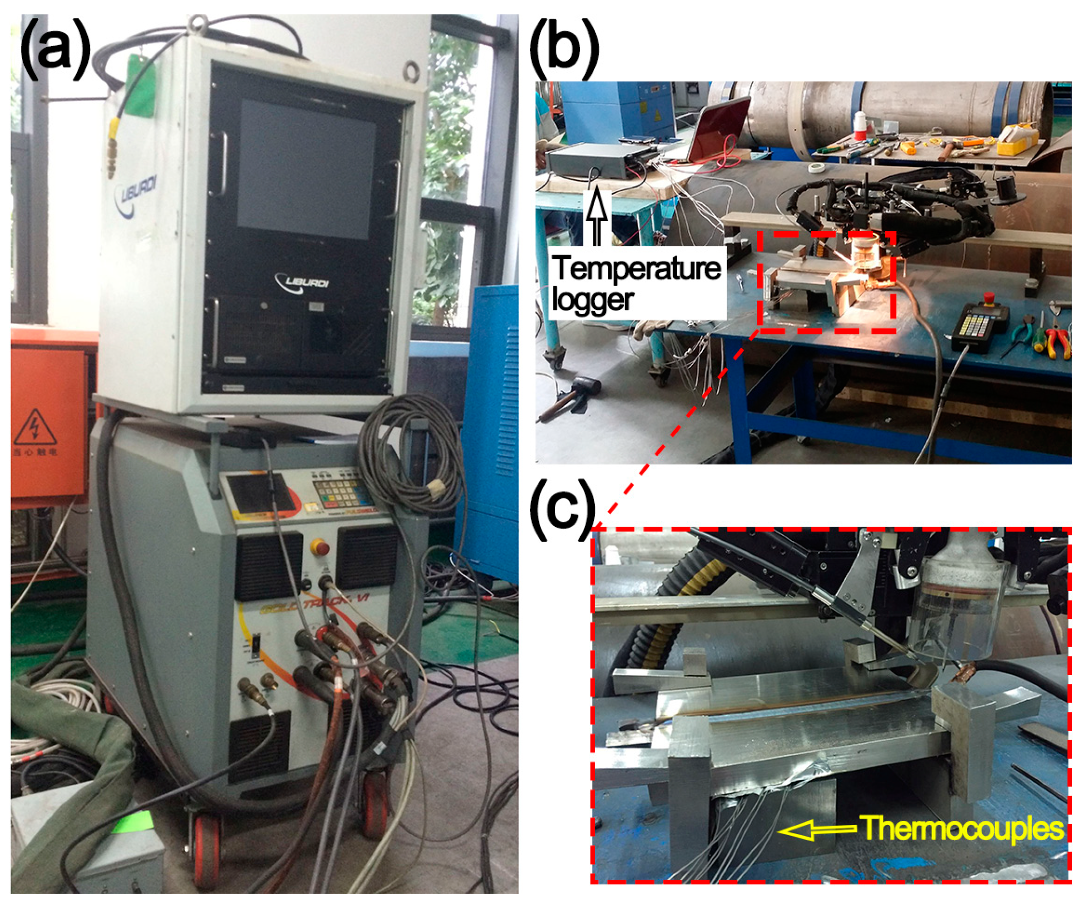
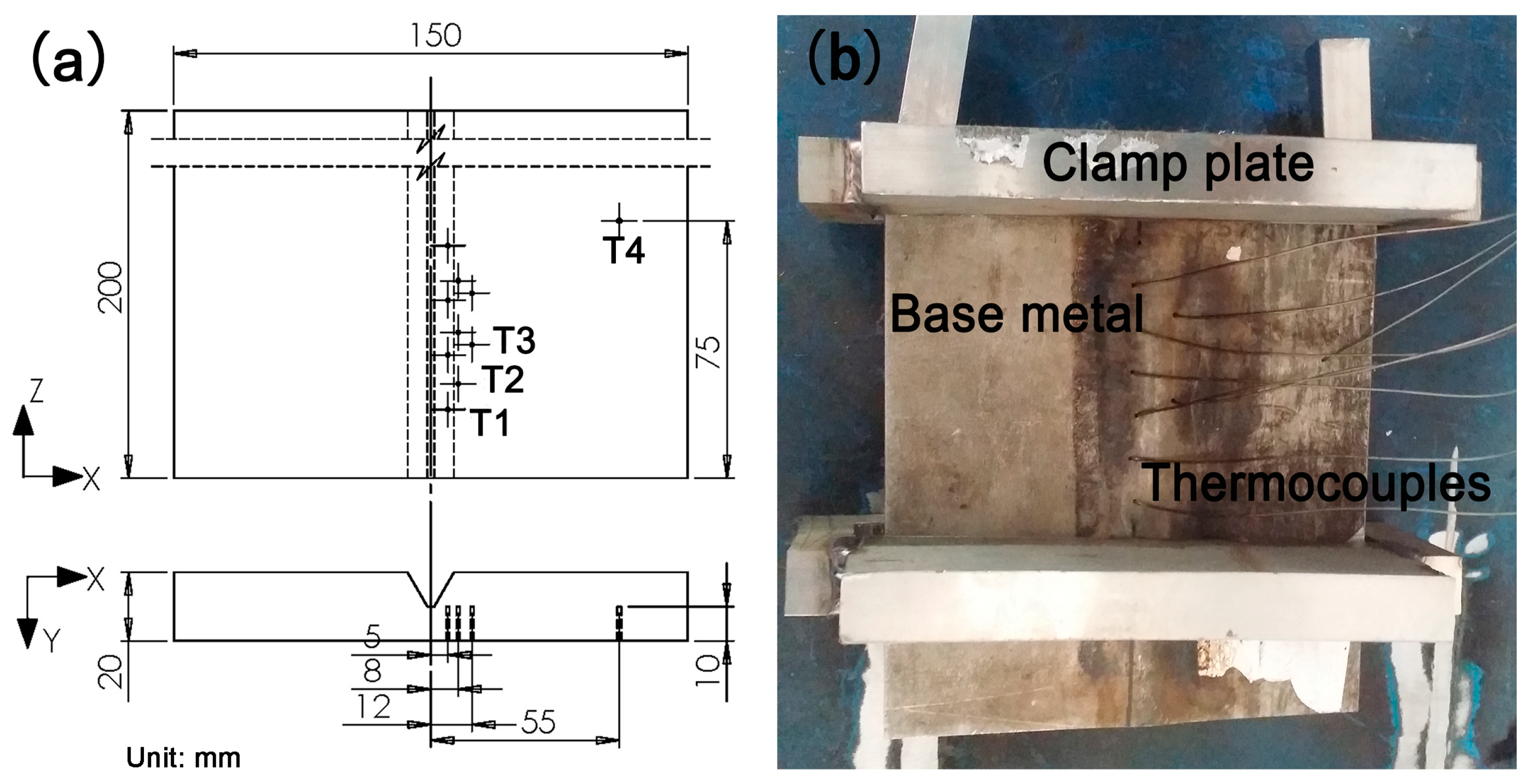
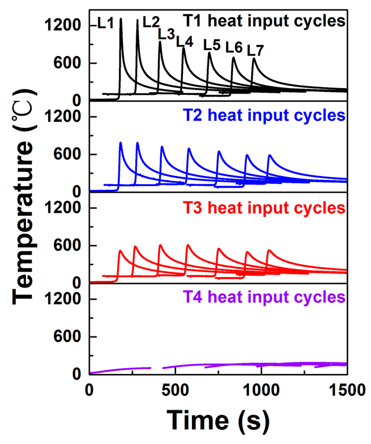
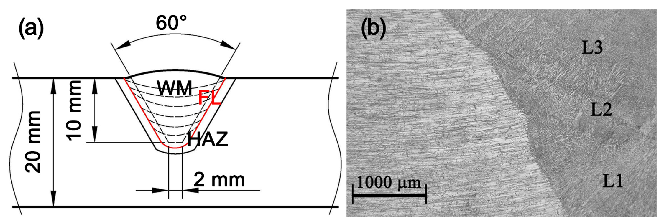
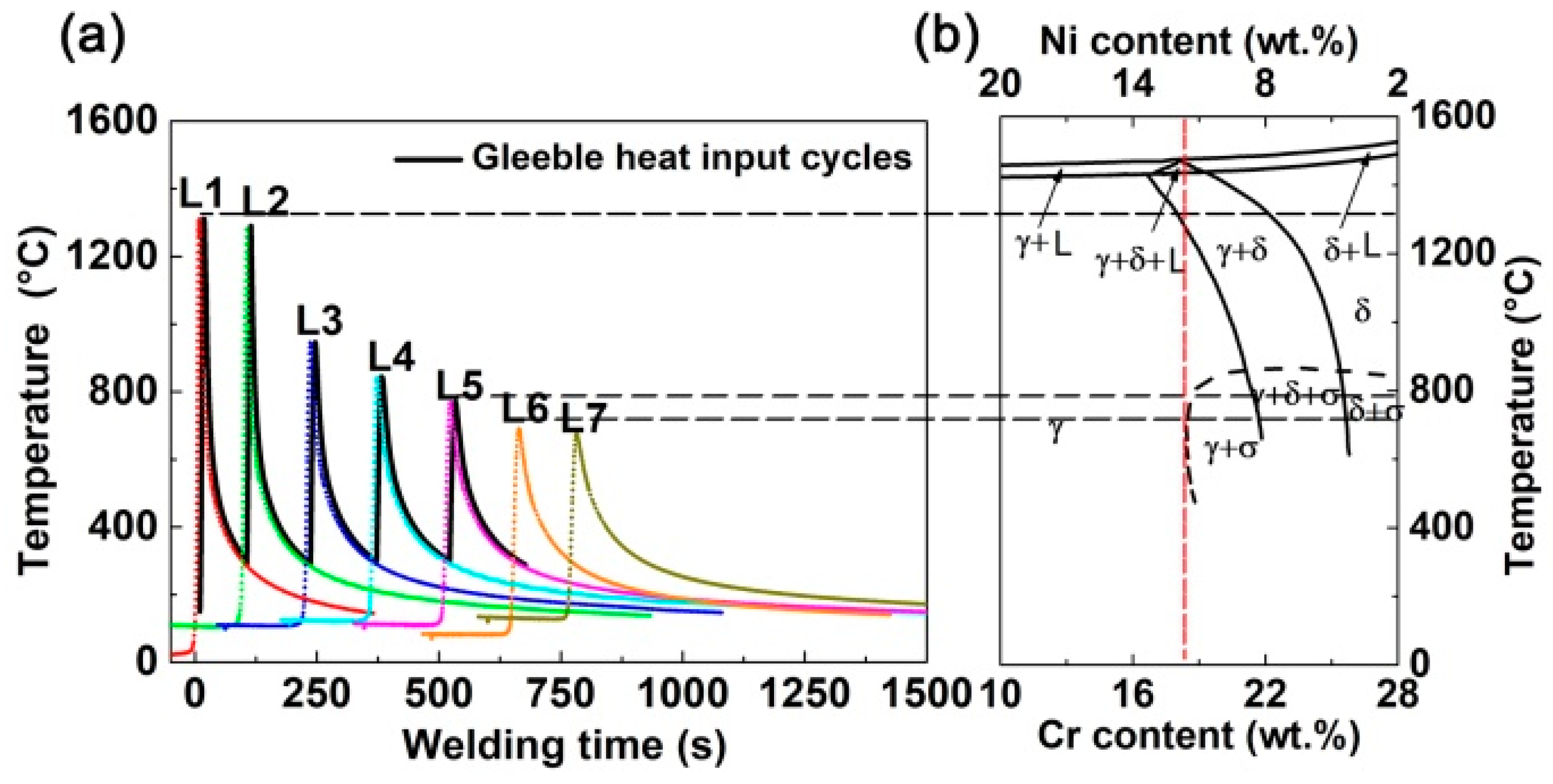
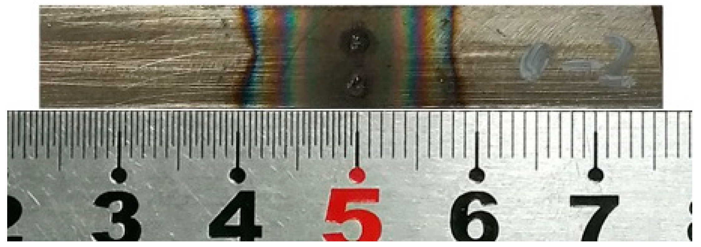
3.1. Heat Input of HAZ in the Multi-Bead Welding

The peak temperature attained during the multi-bead welding was significant, which could alter the microstructure and mechanical properties of the HAZ [16]. Figure 6 shows the temperature profiles measured at the T1–T4 positions for the L1–L7 beads with a time when the temperature was down to 300 °C. The interpass temperature lower than 300 °C between beads was controlled by the cooling time of L1–L7. As each bead performed, the temperatures at the T1–T4 positions rapidly reached a peak when the weld pool was nearest to the thermocouple, and then gradually decreased to room temperature. The maximum peak temperature of 1314 °C at the T1 position was reached during the L1 bead. The other peak temperatures of 1290 °C, 945 °C, 843 °C, 768 °C, 695 °C, and 677 °C was recorded for the L2–L7 beads, respectively. The peak temperatures of 788 °C, 784 °C, 724 °C, 694 °C, 648 °C, 589 °C, and 587 °C at the T2 position was reached for the L1–L7 beads. A similar trend in the peak temperature at the T2 position for L1–L7 was observed as that at the T1 position. However, the maximum peak temperature reached at the T3 position appeared during the L3 bead because of the welding heat input and the residual temperature of the welding plate. The peak temperatures of the T1–T4 positions became lower subsequently. The temperatures at the T4 position were not more than 200 °C during the overall welding process, implying that the distribution of welding temperature field is independent of the dimensions of welding plate. A similar temperature field of the HAZ was reported on AISI 321 austenitic stainless steel by GTAW [16], on nickel sheet welded by laser beam [17], and temperature field during multi-bead GMAW Surfacing [18]. Therefore, the heat input at the T1 position, nearest to the fusion line of the welding joint with the highest peak temperature among the T1–T4 positions was chosen as a heat input to simulate the HAZ of the repeated welding. The AW specimen was prepared under the heat input introduced once, and the RW1–RW5 specimens were under the heat input by 1–5 times as the repeated welding.

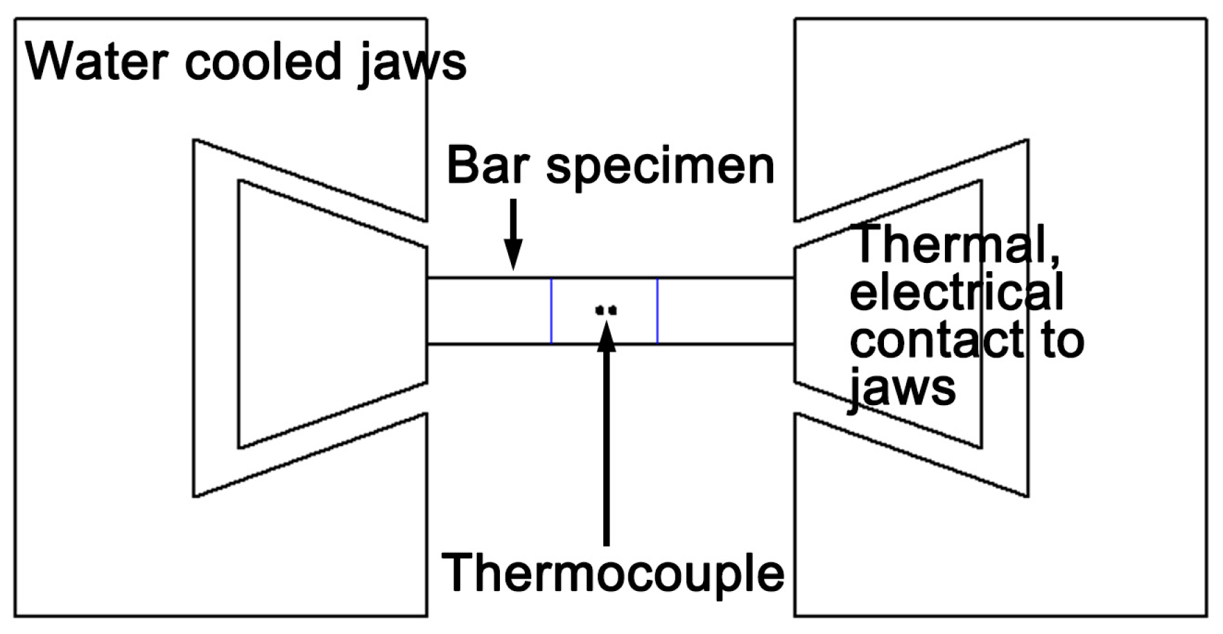
3.2. Gleeble Simulation of the Repeated Welding

Figure 7 shows the thermal cycles of the Gleeble weld-simulator from the temperature field measured at the T1 position and the 70 wt.% Fe pseudo binary phase diagram of the Fe–Cr–Ni alloy with the Cr/Ni ratio. Higher peak temperatures were observed for the L1 and L2 beads, and the significant decreases were for the L3–L7 beads with a gradual incline. The peak temperatures of the L1 and L2 beads were 1314 °C and 1290 °C, corresponding to the time taken to cool from 1200 °C to 800 °C of ∆t12/8 = 6.8 s and 7.6 s. According to the 70 wt.% Fe pseudo binary phase diagrams of the Fe–Cr–Ni alloy [19], the solid-state phase transformation would follow the δ + γ → γ path during the L1 and L2 beads. The peak temperatures of the L3–L5 beads were 945 °C, 843 °C, and 768 °C. Between the peak temperatures of the L3–L5 beads, the γ phase would be stabilized according to Figure 7b. Moreover, a lower peak temperature than the 900 °C of L4 and L5 beads could not motivate the solid-state phase transformation, but may cause interphase precipitation and the distribution of residual stress and strain [20]. For temperatures below 700 °C, the phase transformation of the δ and γ phases would not happen. Hence, the welding thermal cycles after five beads had little effect on the transformation of the HAZ for the Fe–Cr–Ni austenitic stainless steel. Therefore, the thermal cycles of the L1–L5 at position T1 were chosen as the input of the Gleeble weld-simulator. Figure 8 shows a photo of a typical specimen after HAZ simulation using the Gleeble simulator that was approximately 10 mm in width at the center. These specimens were used to study the microstructure and mechanical properties.

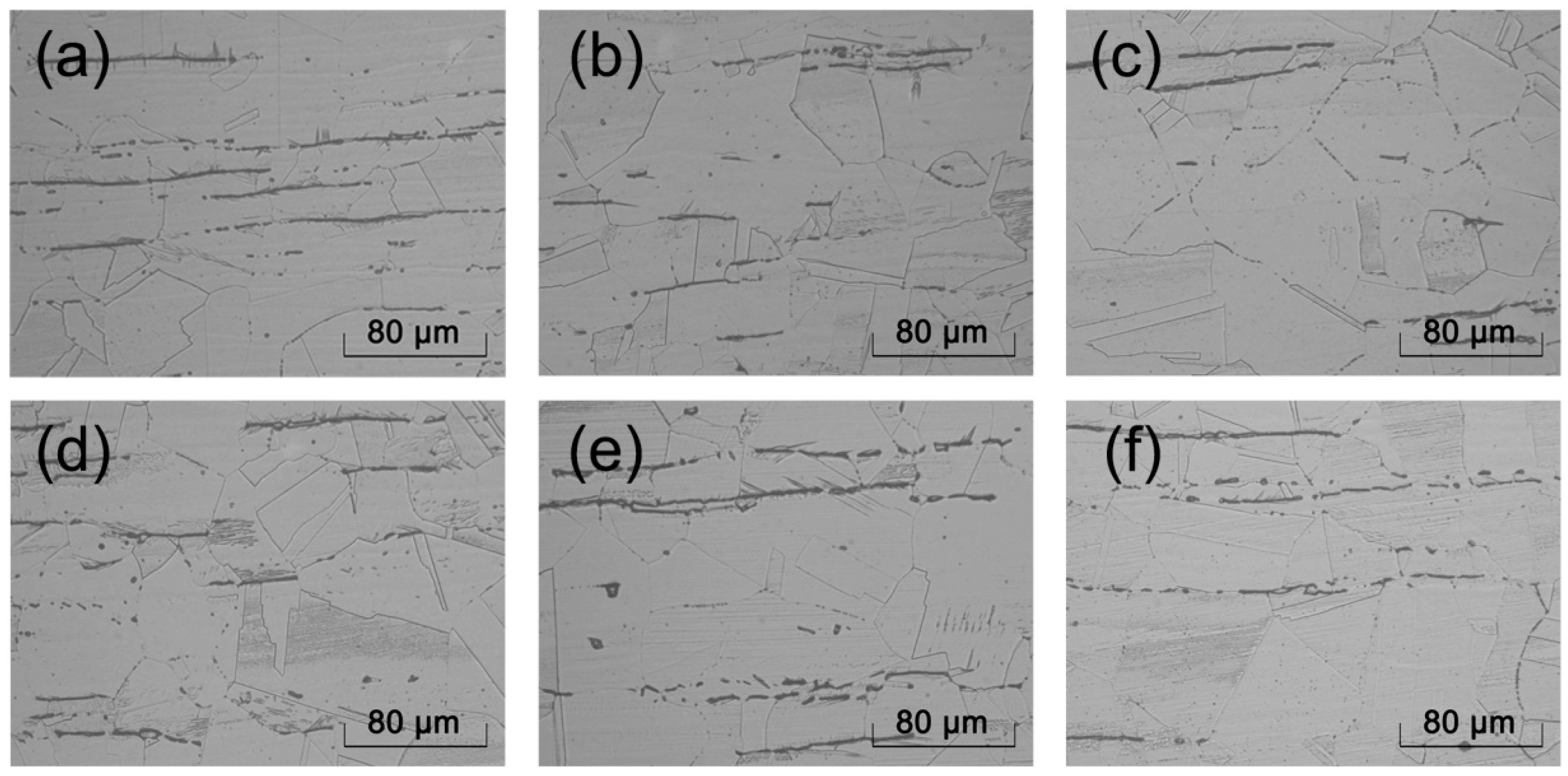
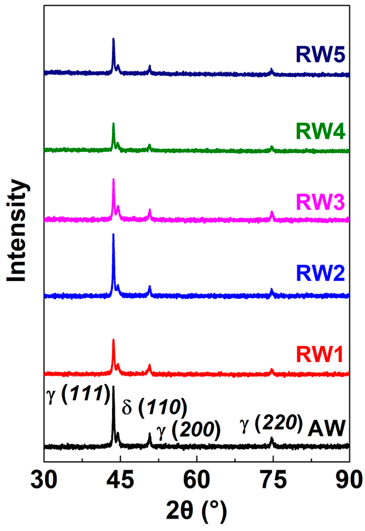
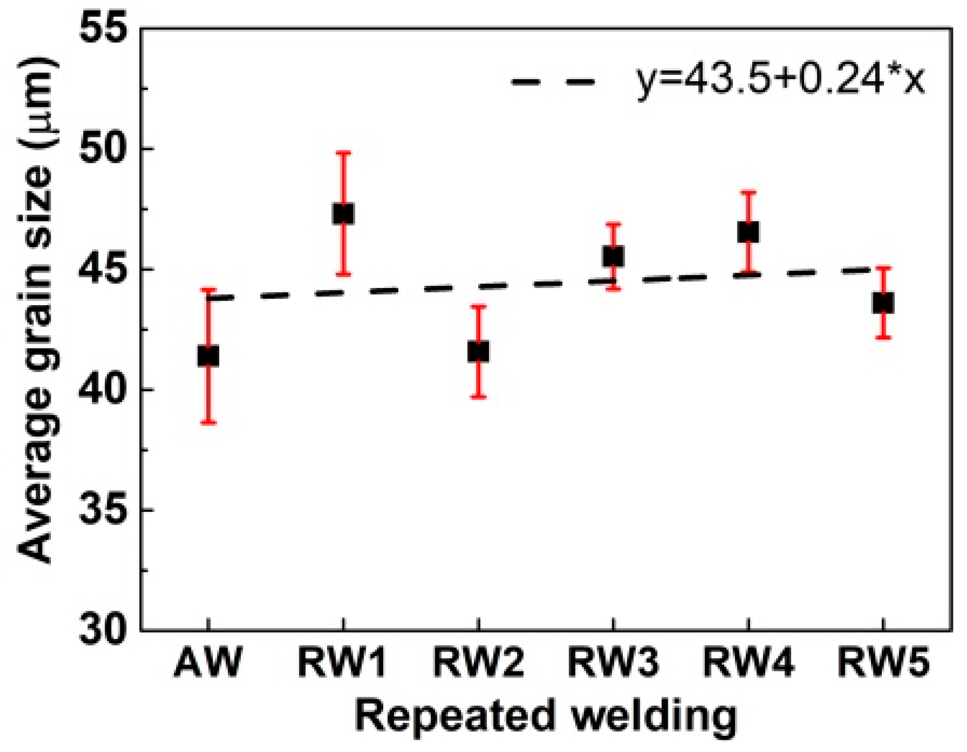
3.3. Microstructure of the Repeated Welding Specimens

Figure 9 shows the optical micrographs of the AW and RW1–RW5 specimens obtained by the Gleeble weld-simulator. The microstructure of the AW and RW1–RW5 specimens consisted of lathy δ ferrite in the matrix. The matrix mostly comprises equiaxcrystal and twins, and a small number of secondary twins. The lathy inclusions were in the grain boundaries. With the repeated welding, the laths’ length of inclusions was changed. The AW specimen had the longest δ-ferrite lath of about 48 μm, and the RW1 specimen had the shortest δ-ferrite at about 30 μm. Longer δ-ferrite lath and disperser δ-ferrite precipitates were simultaneously observed. Figure 10 shows the XRD patterns for the AW and RW1–RW5 specimens. The XRD results show that γ-austenite was the predominant phase for all the samples along with minor levels of δ-ferrite.
Figure 11 shows the average grain size of the as-welded and repeated welding specimens by metallography for the AW and RW1–RW5, respectively. The grain size assessment of the AW and RW1–RW5 specimens was carried out using the linear intercept method according to ASTM E-112 standard. The relative measurement error was less than 6%, which met the ASTM E-112 standard requirements with an error of less than 10%. With repeated welding, the average grain size increased first to a maximum value of 47.3 μm for the RW1 specimen from the minimum value of 41.4 μm for the AW specimen, then decreased to 41.6 μm for the RW2 specimen followed up to 43.6 μm for the RW5 specimen. A slight variation in the average grain size was obtained in the range of 41.4–47.3 μm for the AW and RW1–RW5 specimens. The linear regression function was used to fit the relationship between the grain size and the repeated welding times, as shown in Figure 11. With the repeated welding times, the grain size gradually increased.
Figure 12 shows the average δ-ferrite content measured in AISI 304N austenitic stainless steel of the as-welded and repeated welding for the AW and RW1–RW5. With the repeated welding, the δ-ferrite content first decreased from 3.13 vol.% for the AW specimen to 0.69 vol.% for the RW2 specimen, then increased to 1.50 vol.% for the RW4 specimen, and finally decreased to 1.18 vol.% for the RW5 specimen. The largest and smallest content of δ-ferrite was obtained for the AW and RW2 specimens, respectively. A similar trend in the δ-ferrite content was observed by the magnetic method, as 1.10 FN (Ferrite Number), 0.75 FN, 0.63 FN, 0.88 FN, 0.95 FN, and 0.64 FN with the AW and RW1–RW5 specimens.
Figure 13 shows the networks of misorientation angles of >15° in the austenitic matrices for the repeated welding specimens using EBSD. Grain boundaries can be classified by the misorientation angle between two grains into two categories: low-angle boundaries (LAB) and high-angle boundaries (HAB) [21]. LABs are defined as boundaries with misorientation angles <15°; HAB are those with misorientation angles >15°. As the number of repeated welds increased, a variation in the LAB fraction of 68.2–77.7% was observed, whereas the HAB fractions of the AW and RW1–RW5 specimens showed large variations of 30.1%, 27.9%, 31.8%, 25.7%, 22.3%, and 23.7%, respectively. Networks of HAB in the AW and RW1–RW5 specimens were observed in the misorientation maps. The networks of HABs were distributed continuously in AW, RW1, and RW2 with small degrees of clustering. In comparison, those in RW3, RW4, and RW5 had sparse distributions and poor continuity.

3.4. Mechanical Properties of the Repeated Welding Specimens

Figure 14 shows the tensile strength of the AW and RW1–RW5 specimens by the as-welded and repeated welding, respectively, in the Gleeble weld-simulator. Tensile testing was realized according to ASTM E-8. The failure zones were all located at the centers of the cylinder specimens. With repeated welding, the ultimate tensile strength (UTS) first increased from 555 MPa for the AW specimen to the maximum of 670 MPa for RW2, then decreased to 525 MPa for RW4, and was followed up to 530 MPa for RW5. A similar trend in the yield strength (YS) was obtained to that of UTS. The highest UTS and YS were obtained at 670 MPa and 245 MPa for RW2, and the lowest values of 525 MPa and 190 MPa were for RW4. The UTSs of RW1–RW3 were higher than those of AW, and all above 550 MPa of the UTS of AISI 304N austenitic stainless steel, though a decreased UTS for the RW3 specimen was observed relative to that of the RW1 and RW2 specimens.
Figure 15 shows the impact energy of the AW and RW1–RW5 specimens for once welding and 1–5 times repeated welding, respectively, in the Gleeble weld-simulator. Impact testing was performed at room temperature according to ASTM E-23. Three specimens of each set were taken for impact testing. With the repeated welding, the impact energy decreased first to the minimum value of 225 J for RW1 from the 246 J for the AW, then increased to the maximum value of 272 J for the RW3 followed by a decline to 254 J for the RW5 specimen. The impact energy of all the repeated heating specimens was very high with a variation in the range of 225–272 J.

4. Discussion

AghaAli et al. investigated the effects of repeated welding four times on the microstructure and mechanical of AISI 316L austenitic stainless steel. The grain size decreased from 23.46 μm for the once welded specimen to 23.00 μm for the fourth welding. For the 2–4 times repeated welding specimens, the grains grew and then became bigger. The grain size of the HAZ of the repeated welding joint reached 25.65 μm for the fourth repeated welding [6]. The variation in grain size of the repeated welding specimens was not consistent with those ones in the Gleeble weld-simulator in this work. This inconsistency may be due to the fact that the manual SMAW provides an unstable welding heat input when compared with that in Gleeble weld-simulator which has an effective way to obtain the stable welding heat input. It is also difficult to accurately locate the HAZ of the actual repeated welding joints, e.g., about 1–2 mm.
The effects of the repeated welding on the microstructure and mechanical properties of the HAZ in AISI 304N austenitic stainless steel were investigated in the Gleeble weld-simulator. The repeated phase transformation between δ + γ and γ may occur in the microstructure of the HAZ under the repeated welding consisting of multiple bead thermal cycles. The grain size of the as-welded specimen was larger than that of the base austenitic stainless steel, from 26 μm in the base metal to 41.4 μm. The repeated welding specimens had a slight variation in grain size in the range of 41.4–47.3 μm. It was found that the δ-ferrite content fluctuated with the repeated welding. Lathy δ-ferrite and disperser δ-ferrite precipitates were simultaneously observed, caused by the heat input of the welding [22]. Tseng et al. [23] studied the formation of austenite from δ-ferrite in AISI 304L stainless steel. The Cr and Ni elements could concentrate or migrate at the grain boundaries of the austenite matrix in the austenitic stainless steel due to rapid cooling or insufficient hot working, e.g., welding. This would lead to a variation in the local Cr/Ni ratio. As shown in Figure 7b, at the same peak temperature, the phase diagram enters the δ + γ area with the ratio of Cr/Ni increasing; therefore, δ-ferrite is formed again. This may result in a variation in the content of δ-ferrite with repeated welding.
During repeated welding, the δ-ferrite content had a significant effect on the tensile properties of the repeated welding specimens. The highest UTS and YS of 670 MPa and 245 MPa for the RW2 specimen corresponded to the lowest δ-ferrite content of 0.69 vol.%. The lowest UTS and YS of 525 MPa and 190 MPa for the RW4 specimen corresponded to the largest δ-ferrite content of 1.5 vol.%. In Figure 16, linear regression functions were used to fit the relationship between tensile strength and δ-ferrite content, and tensile strength and austenitic grain size. By increasing the grain size and the δ-ferrite content, the tensile strength decreased. The slope of the tensile strength-ferrite content fitted line was larger than that of the tensile strength-grain size fitted line, which means that the δ-ferrite content affected tensile strength more significantly than the austenitic grain size under this experimental condition. For the austenitic stainless steel with good toughness, the tensile fracture was strongly influenced by the secondary phase during the tensile process with crack nucleation and propagation. When plastic deformation occurred in the austenitic stainless steel, a great number of dislocations were built up around the secondary phase. With the effect of dislocation pile-up and tensile stress, a head dislocation of the pile-up migrated to the boundary of the secondary phase [21]. As a result, a tensile crack was generated at the interface between the austenite and δ-ferrite. During crack propagation, the crack path was much longer for the HABs than the LABs. When cracks encountered the HAB, they required more energy to induce a boundary slip, thus preventing crack propagation [24]. Furthermore, the UTS and YS were affected by the combined effects of δ-ferrite and HAB during the crack initiation and propagation.
The impact energy of the repeated welding specimens was dependent on the grain size of the austenite and the contents of δ-ferrite. The highest impact energy of 272 J for the RW3 specimen corresponded to the larger grain size of 45.5 μm. The crack growth energy accounted for a very large proportion of the total impact energy [25]. As the grain size was big, a high roughness, and a long crack path length was generated [26]. The energy required for crack propagation increased. Therefore, the change of impact energy basically depended on that of the average grain size, that is, when the grain size increased, the impact energy increased. Nevertheless, the δ-ferrite content had an adverse effect on the impact energy. As the austenite and δ-ferrite had different crystal structures, the boundaries of δ-ferrite/austenite had weak coherence when compared to that of the austenite/austenite [27]. When the impact crack was in the propagation, the crack tip easily passed through δ-ferrite with lower impact energies. Therefore, the impact energy decreased as the δ-ferrite content decreased. In Figure 16, linear regression functions were also used to fit the relationships between impact energy and δ-ferrite content and austenitic grain size. The gentle slope of the impact energy-ferrite fitted line was much closer to that of the impact energy-grain size fitted line, which means that the toughness properties of the HAZ for the repeated welding specimens were mildly determined by both the grain size and the δ-ferrite content.
In our work, the mechanical properties after each repeated welding do not change significantly. However, the UTSs of the RW1–RW3 specimens were higher than those of the AW specimen, all above the base metal UTS of 550 MPa, i.e., the required minimum UTS of AISI 304N austenitic stainless steel, though a decreased UTS of the RW3 specimen was observed relative to that of the RW1 and RW2 specimens. The UTS of the RW3 specimen also satisfied the ASME IX that was stated to qualify a welding procedure [28]. The tensile strength of the weld should be greater than or equal to the specified minimum tensile strength of the base metal. However, following repeated welding three times, the tensile strength of the RW4 specimen was lower than 550 MPa, which did not meet the requirements of the ASME IX. The impact energy of the RW1–RW5 specimens varied from 246 J to 272 J, and were all more than the minimum impact energy of 56 J as per the requirements of the ASME BPVC III NB subsection. At present, welding seams should not be repaired more than twice in the same location according to some welding specifications. The mechanical properties of specimens with repeated welding up to three times also met the requirements of the ASME. Furthermore, one time more repeated welding would offer economic advantages to power plants as the equipment could prolong service life.

5. Conclusions

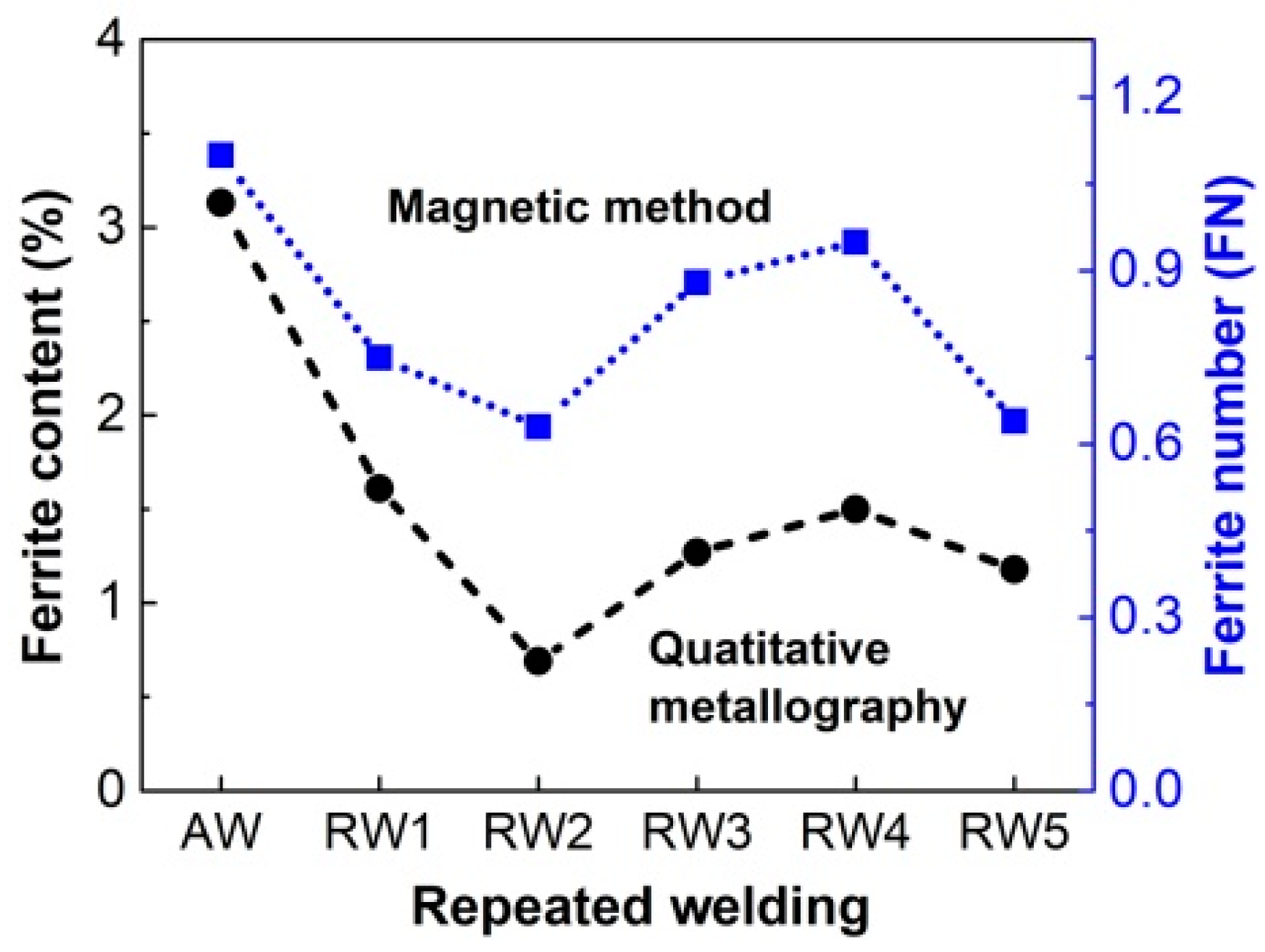
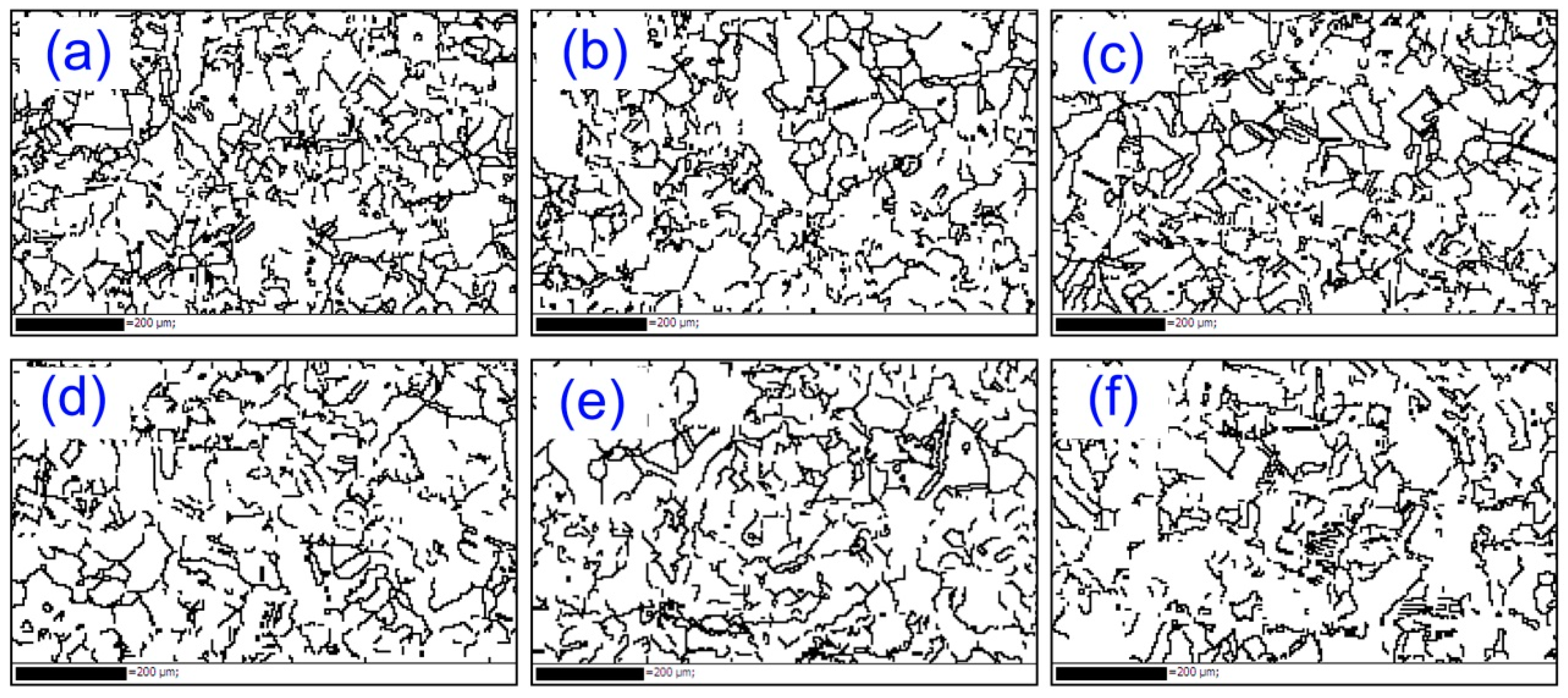
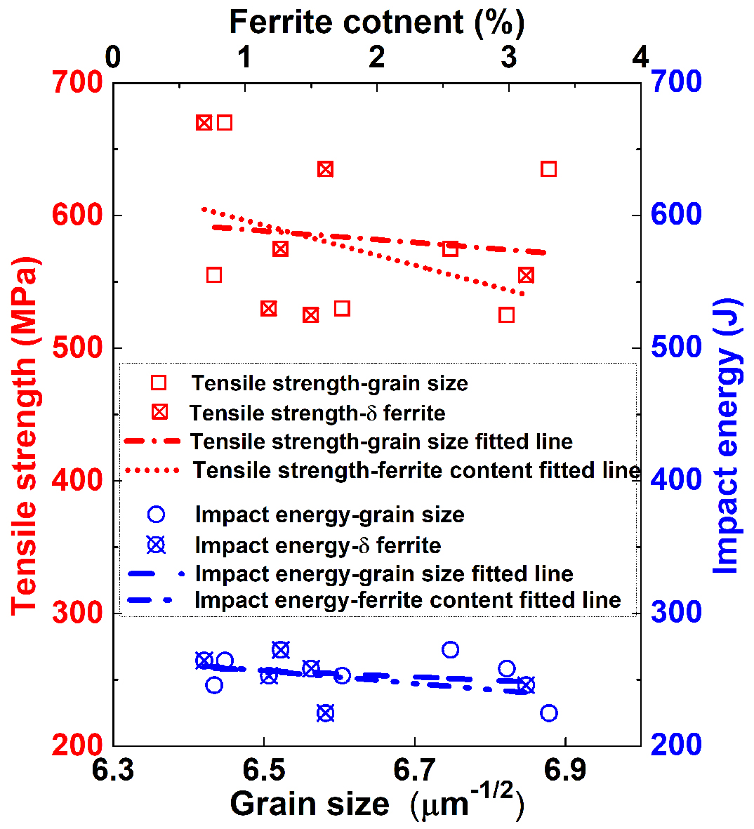
  • Uniform HAZ specimens were prepared under the measured temperature field by the Gleeble weld-simulator to evaluate the microstructure of the repeated welding joints. With the increasing number of repeated welding, the average grain size of austenite fluctuated from 41.4 μm to 47.3 μm, and the content of δ-ferrite ranged from 0.69 vol.% to 3.13 vol.%.
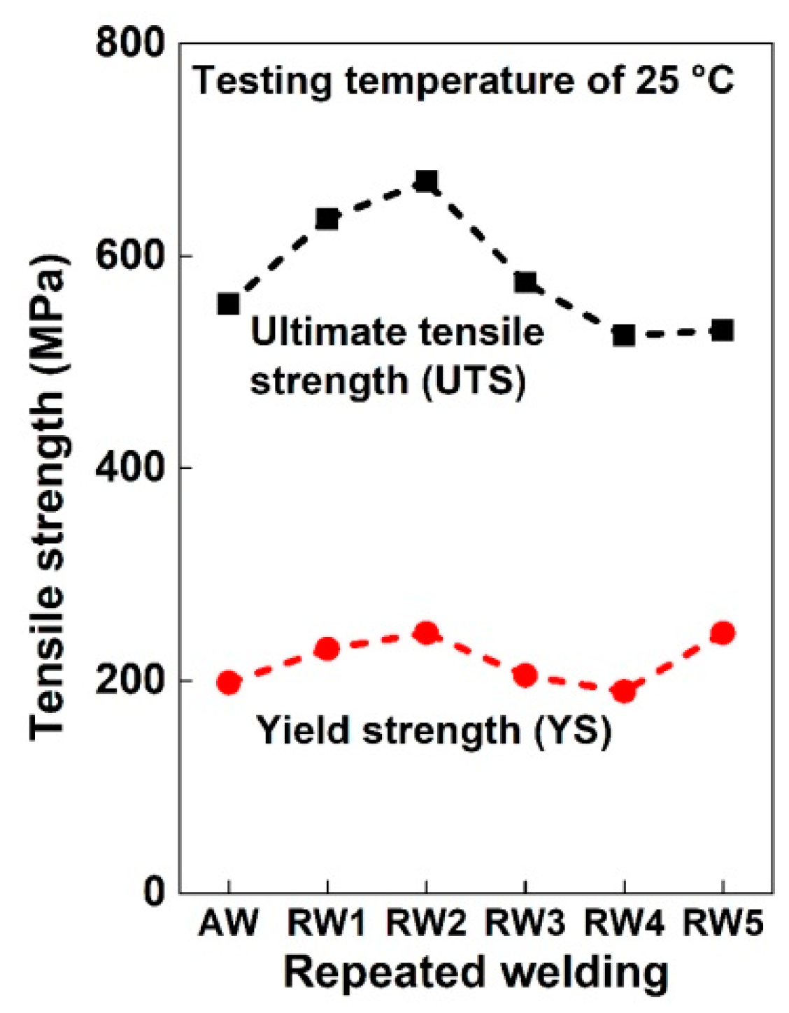
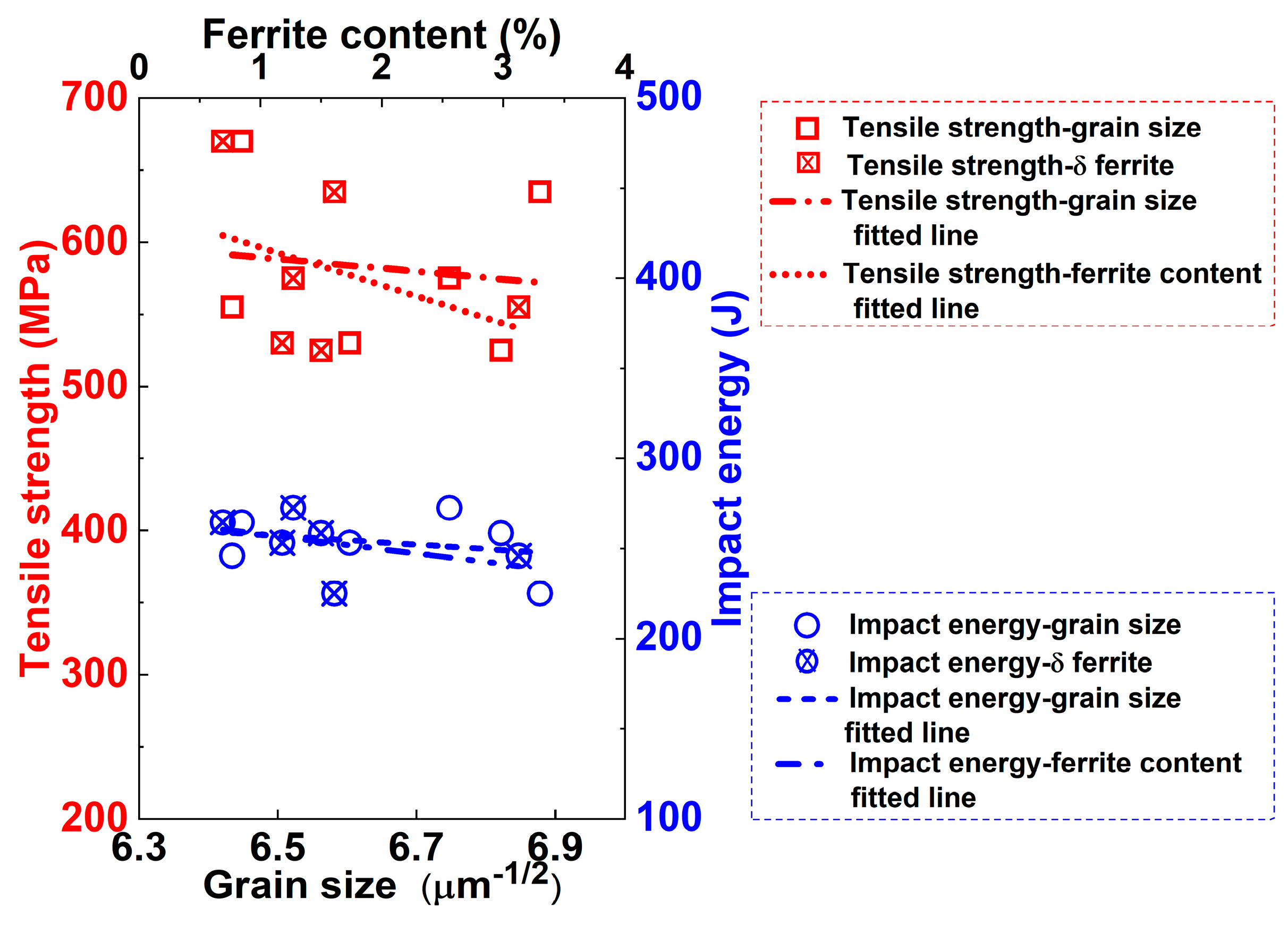
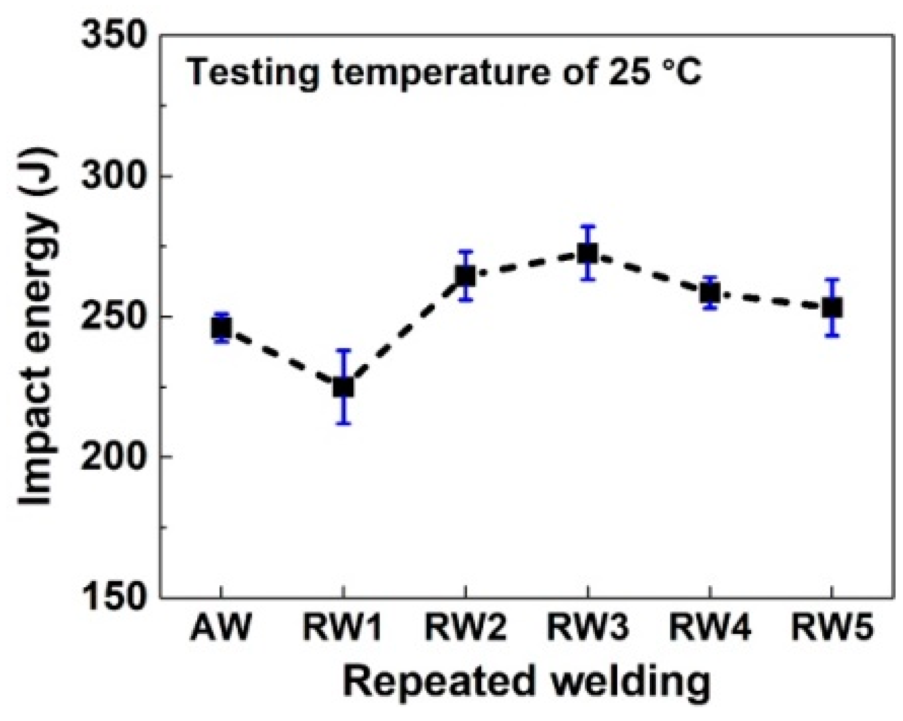
  • The ultimate tensile strength and yield strength mainly depended on the δ-ferrite content and HAB frequency, and the impact energy mainly depended on both the austenitic grain size and the δ-ferrite content. The highest UTS and YS were obtained for the RW2 specimen with the minimum δ-ferrite content, and the lowest values were for the RW4 specimen with the maximum δ-ferrite content. A slight variation in the impact energy was observed for the RW1–RW5 specimens.
  • The UTSs of the RW1–RW3 specimens were higher than those of the AW specimen, and all were above the UTS of the base austenitic stainless steel of 550 MPa to the ASME standard. The impact energy of all specimens was much higher than the ASME standard of 56 J. Repeated welding of up to three times met the requirements of construction, maintenance, and repair, considering the matching strength and toughness in industry.

Author Contributions

Methodology, Y.H.G., D.Z., and L.L.; Project administration, M.K.L.; Supervision, L.L.; Writing—original draft, Y.H.G.; Writing—review & editing, M.K.L.

Funding

This research was funded by the National Basic Research Program of China (973 Program) under Grant No. 2015CB057306.

Acknowledgments

The authors are grateful to Xuemin Pan, Jianying Gao, and Ning Ding for their helpful discussion and technical assistance.

Conflicts of Interest

The authors declare no conflict of interest.

References

  1. Code for Construction of Field Equipment, Industrial Pipe Welding Engineering, GB Standard 50236-2011; China Planning Press: Beijing, China, 2011.
  2. Standard Construction Standard for Welding of Transportation Pipeline; IPS-C-PI-2070(2); Iranian Petroleum Standards: Tehran, Iran, 2001.
  3. RCC-M Design and Construction Rules for Mechanical Components of PWR Nuclear Island Section IX Welding; AFCEN: Pairs, France, 2002.
  4. Rules for Construction of Nuclear Facility Components Division 1-Subsection NB Class 1 Components; ASME Section III; American Society of Mechanical Engineers: New York, NY, USA, 2013; Volume 3.
  5. Lant, T.; Robinson, D.L.; Spafford, B.; Storesund, J. Review of weld repair procedures for low alloy steels designed to minimize the risk of future cracking. Int. J. Press. Vessel. Pip. 2001, 78, 813–818. [Google Scholar] [CrossRef]
  6. AghaAli, I.; Farzam, M.; Golozar, M.A.; Danaee, I. The effect of repeated repair welding on mechanical and corrosion properties of stainless steel 316L. Mater. Des. 2014, 54, 331–341. [Google Scholar] [CrossRef]
  7. Lin, C.M.; Tsai, H.L.; Cheng, C.D.; Yang, C. Effect of repeated weld-repairs on microstructure, texture, impact properties and corrosion properties of AISI 304L stainless steel. Eng. Fail. Anal. 2012, 21, 9–20. [Google Scholar] [CrossRef]
  8. Vega, O.E.; Hallen, J.M.; Villagomez, A.; Contreras, A. Effect of multiple repairs in girth welds of pipelines on the mechanical properties. Mater. Charact. 2008, 59, 1498–1507. [Google Scholar] [CrossRef]
  9. Nascimento, M.P.; Voorwald, H.J.C.; Payão Filho, J.D.A.C. Effects of several TIG weld repairs on the axial fatigue strength of AISI 4130 aeronautical steel-welded joints. Fatigue Fract. Eng. Mater. Struct. 2012, 35, 191–204. [Google Scholar] [CrossRef]
  10. Liu, W.; Lu, F.; Yang, R.; Tang, X.; Cui, H. Gleeble simulation of the HAZ in Inconel 617 welding. J. Mater. Process. Technol. 2015, 225, 221–228. [Google Scholar] [CrossRef]
  11. Kardoulaki, E.; Lin, J.; Balint, D.; Farrugia, D. Investigation of the effects of thermal gradients present in Gleeble high-temperature tensile tests on the strain state for free cutting steel. J. Strain Anal. Eng. Des. 2014, 49, 521–532. [Google Scholar] [CrossRef]
  12. Moeinifar, S.; Kokabi, A.H.; Hosseini, H.R.M. Effect of tandem submerged arc welding process and parameters of Gleeble simulator thermal cycles on properties of the intercritically reheated heat affected zone. Mater. Des. 2011, 32, 869–876. [Google Scholar] [CrossRef]
  13. Hsieh, R.-I.; Liou, H.-Y.; Pan, Y.-T. Effects of cooling time and alloying elements on the microstructure of the Gleeble-simulated heat-affected zone of 22% Cr duplex stainl ess steels. J. Mater. Eng. Perform. 2001, 10, 526–536. [Google Scholar] [CrossRef]
  14. Silwal, B.; Li, L.; Deceuster, A.; Griffiths, B. Effect of postweld heat treatment on the toughness of heat-affected zone for grade 91 steel. Weld. J. Res. Suppl. 2013, 92, 80–87. [Google Scholar]
  15. ГOCГ 6996 Welding Joints. Methods of Mechanical Properties Determination; Kaluga typography Standards Press: Moscow, Russia, 1966. [Google Scholar]
  16. Nakhodchi, S.; Shokuhfar, A.; Iraj, S.A.; Thomas, B.G. Evolution of temperature distribution and microstructure in multipass welded AISI 321 stainless steel plates with different thicknesses. J. Press. Vessel Technol. 2015, 137, 061405. [Google Scholar] [CrossRef]
  17. Li, M.-Y.; Kannatey-Asibu, E., Jr. Monte Carlo simulation of heat-affected zone microstructure in laser-beam-welded nickel sheet. Weld. J. Res. Suppl. 2002, 37–44. [Google Scholar]
  18. Winczek, J. Modeling of temperature field during multi-pass GMAW surfacing or rebuilding of steel elements taking into account the heat of the deposit metal. Appl. Sci. 2016, 7, 6. [Google Scholar] [CrossRef]
  19. Lippold, J.C.; Savage, W.F. Solidification of austenitic stainless steel weldments: Part I—A proposed mechanism. In AWS 60th Annual Meeting; American Welding Society: Detroit, USA, 1979; pp. 362–374. [Google Scholar]
  20. Moon, J.; Lee, J.; Lee, C. Prediction for the austenite grain size in the presence of growing particles in the weld HAZ of Ti-microalloyed steel. Mater. Sci. Eng. A 2007, 459, 40–46. [Google Scholar] [CrossRef]
  21. Gourgues, A.-F. Electron backscatter diffraction and cracking. Mater. Sci. Technol. 2002, 18, 119–133. [Google Scholar] [CrossRef]
  22. Kamiya, O.; Kumagai, K.; Kikuchi, Y. Effects of δ Ferrite morphology on low temperature fracture toughness of SUS304L steel weld metal. Trans. Jpn. Weld. Soc. 1990, 21, 57–62. [Google Scholar]
  23. Tseng, C.C.; Shen, Y.; Thompson, S.W.; Mataya, M.C.; Krauss, G. Fracture and the formation of Sigma Phase, M23C6, and Austenite from Delta-Ferrite in an AISI 304L stainless steel. Metall. Mater. Trans. A 1994, 25, 1147–1158. [Google Scholar] [CrossRef]
  24. Sinha, S.; Kim, D.-I.; Fleury, E.; Suwas, S. Effect of grain boundary engineering on the microstructure and mechanical properties of copper containing austenitic stainless steel. Mater. Sci. Eng. A 2015, 626, 175–185. [Google Scholar] [CrossRef]
  25. Harvey, D.P., II; Terrell, J.B.; Sudarshan, T.S.; Louthan, M.R., Jr. Participation of hydrogen in the impact behavior of 304L stainless steel. Eng. Fract. Mech. 1993, 46, 455–464. [Google Scholar] [CrossRef]
  26. Buirette, C.; Huez, J.; Gey, N.; Vassel, A.; Andrieu, E. Study of crack propagation mechanisms during Charpy impact toughness tests on both equiaxed and lamellar microstructures of Ti-6Al-4V titanium alloy. Mater. Sci. Eng. A 2014, 618, 546–557. [Google Scholar] [CrossRef]
  27. Lee, D.N.; Han, H.N. Orientation relationships between precipitates and their parent phases in steels at low transformation temperatures. J. Solid Mech. Mater. Eng. 2012, 6, 323–338. [Google Scholar] [CrossRef]
  28. Welding, Brazing and Fusing Qualifications, ASME Section IX; American Society of Mechanical Engineers: New York, NY, USA, 2013; Volume IX.
Figure 1. Profiles of the welding joint: (a) welding groove geometry; and (b) macro-image of cross section cover the HAZ.
Metals 08 00773 g001
Figure 2. Experimental system for measurement of welding thermal cycles: (a) automatic gas tungsten arc welding machine; (b) temperature logger; and (c) thermocouples and a welding plate.
Metals 08 00773 g002
Figure 3. Arrangement of the K-type thermocouple with a thermocouple wire diameter of 0.1 mm: (a) dimension of welding plate and location of thermocouples; and (b) thermocouples attached to the welding plate.
Metals 08 00773 g003
Figure 4. Schematic of the Gleeble simulation specimen of the welding HAZ.
Metals 08 00773 g004
Figure 5. Dimensions of tensile and impact specimens of the repeated welding specimens: (a) tensile specimen; and (b) Charpy-V impact specimen.
Metals 08 00773 g005
Figure 6. Temperature filed measured at the T1–T4 positions for the L1–L7 beads.
Metals 08 00773 g006
Figure 7. Heat input of the Gleeble weld-simulator from the temperature field measured at the T1 position in the 70 wt.% Fe pseudo binary phase diagram of the Fe–Cr–Ni alloy with the Cr/Ni ratio: (a) heat input for Gleeble weld-simulator; and (b) 70 wt.% Fe pseudo binary phase diagram of Fe–Cr–Ni.
Metals 08 00773 g007
Figure 8. A photo of typical specimen after HAZ simulation using the Gleeble simulator with about a 10 mm width located at the center.
Metals 08 00773 g008
Figure 9. Optical micrographs of the AW and RW1–RW5 specimens by welding and repeated welding in the Gleeble weld-simulator: (a) AW; (b) RW1; (c) RW2; (d) RW3; (e) RW4; and (f) RW5.
Metals 08 00773 g009
Figure 10. XRD spectrum of the AW and RW1–RW5 specimens.
Metals 08 00773 g010
Figure 11. Average grain size of the AW and RW1–RW5 specimens by metallography.
Metals 08 00773 g011
Figure 12. δ-ferrite contents measured in AISI 304N austenitic stainless steel of the as-welded and repeated welding by the quantitative metallography method and magnetic method for the AW and RW1–RW5 specimens.
Metals 08 00773 g012
Figure 13. Networks of misorientation angles >15° for the repeated welding specimens using EBSD: (a) AW; (b) RW1; (c) RW2; (d) RW3; (e) RW4; and (f) RW5.
Metals 08 00773 g013
Figure 14. Ultimate tensile strength and yield strength of the AW, RW1–RW5 specimens by welding and repeated welding in the Gleeble weld-simulator at room temperature.
Metals 08 00773 g014
Figure 15. Impact energy of the AW, RW1–RW5 specimens by the as-welded and repeated welding in Gleeble weld-simulator at room temperature.
Metals 08 00773 g015
Figure 16. Linear regression of the relationship between tensile strength, impact energy and grain size, and ferrite content.
Metals 08 00773 g016
Table 1. Chemical composition and mechanical properties of AISI 304N austenitic stainless steel.
Chemical Composition (wt.%)Mechanical Properties
CCrNiMnSiPSNUTSYS
0.05018.5458.2111.6000.5000.0340.0010.120550 MPa240 MPa
Table 2. Welding process parameters used for thermal cycling measurement of the HAZ.
Bead No.Current (A)Volts (V)Travel Speed (mm/s)Feed Rate of Wire (mm/min)Heat Input (kJ/mm)
12609.501.52891.62
22609.201.52891.57
3–72609.501.52891.62

