Article

Tensile Behavior of Sintered Stainless Steel Fiber Felts: Effect of Sintering Joints and Fiber Ligaments

1
State Key Laboratory for Strength and Vibration of Mechanical Structures, Xi’an Jiaotong University, Xi’an 710049, China
2
State Key Laboratory of Porous Metal Materials, Northwest Institute for Nonferrous Metal Research, Xi’an 710016, China
3
State Key Laboratory of Explosion Science and Technology, Beijing Institute of Technology, Beijing 100081, China
*
Author to whom correspondence should be addressed.
Metals 2018, 8(10), 768; https://doi.org/10.3390/met8100768
Submission received: 10 August 2018 / Revised: 30 August 2018 / Accepted: 7 September 2018 / Published: 27 September 2018

Abstract

:
To optimize the tensile properties of sintered 316L stainless steel fiber felts (SSFFs) which is important for their practical applications, the influence of sintering conditions on the microstructure (fiber ligament, sintering joint) and in turn, the tensile properties was investigated experimentally. It was shown that the tensile strength and tensile elongation of SSFFs were dominated by the tensile properties of the fiber ligaments and the bonding strength of the sintering joints. With the increase of sintering temperature versus holding time, the tensile strength of the fiber ligaments dropped significantly, while the sintering joints grew, producing a higher bonding strength between the fibers, resulting in more fibers being involved in the tensile process. These changes in sintering joints and fiber ligaments finally led to a relatively static ultimate strength of SSFFs with a significantly increased elongation, thus with a large increase in tensile fracture energy. The increase of size of the sintering joints also helped to considerably raise the tensile fatigue limit of 316L SSFFs. This research provides a basis to improve the mechanical properties of sintered 316L SSFFs in industrial production.

1. Introduction

Sintered metal fiber felt is a kind of open-network porous metal material composed of metal fibers metallurgically bonded to one another. It exhibits a number of unique properties such as high specific strength, high specific toughness, high specific surface area, and high permeability. As a result, it is widely used for filtration [1], lightweight sandwich core structures [2,3], fuel cell electrodes [4], biomedical devices [5,6], catalyst supports [7], heat transfer elements [8], and environmental noise control devices [9].
As a kind of ultralight cellular material, their mechanical properties need to be fully understood. In earlier times, most studies focused on the relationships between mechanical properties and structural variables such as relative density and fiber orientation [2,3,10,11,12,13]. Zhao et al. [10] investigated the constitutive relationship between the shear modulus and relative density of sintered 316L SSFFs. Markaki et al. [2,3,12] established the single fiber deformation model for sintered SSFF and captured the network structure (e.g., fiber orientation distribution, inter-joint distance) by computed X-ray tomography, then applied the data to a model for prediction of the Young’s modulus [11]. By contrast, only little attention was paid to the effect of such microstructures like the sintering joint and fiber ligament on the mechanical properties. The properties of the sintering joint and fiber ligament are mainly controlled by the manufacturing process. This lack of research has confused the understanding of the mechanical properties of sintered 316L SSFFs. For instance, despite their similar volume fraction and structural characteristic, the values of testing Young’s modulus of 316L SSFFs reported by Zhao et al. [12] are almost two times larger than those reported by Neelakantan et al. [13]. These differences were suggested to arise from different holding pressures during the sintering processes [12]. Sintered 316L SSFFs are far superior in tensile properties to other porous metals such as metal foam and cellular lattices [13]. This advantage makes them more attractive for many applications like industrial filtration. To optimize the tensile properties of 316L SSFFs, the influence of sintering conditions on the microstructure (i.e., sintering joints, fiber ligaments) and tensile properties was deemed worthy of further investigation. Zhou et al. [14] investigated the effect of sintering conditions on the tensile property of Cu fiber felt and found that with the rise of sintering temperature (from 700 °C to 900 °C), the ultimate strength of Cu fiber felt increased by about two times. Liu et al. [15] suggested that the coarse grains of fibers with ‘bamboo like’ structure formed at a high temperature of 1200 °C could lead to severe degradation in the tensile properties of sintered 316L SSFFs. Unfortunately, no reports providing systemic investigation of the complicated relationship between tensile properties, microstructure (i.e., sintering joints, fiber ligaments) are currently available.
To systematically investigate the effect of microstructure on the tensile behavior of sintered 316L SSFFs, a series of sintering experiments with varied sintering temperatures and holding times were conducted. The effect of sintering conditions on the microstructure (i.e., sintering joints, fiber ligaments) was investigated. The relationship between the tensile property of 316L SSFFs and the characteristic sizes of sintering joints and the strength of single fiber was established. The influence of sintering joints and fiber ligaments on the fatigue response of 316L SSFFs was also investigated to thoroughly understand the effect of sintering joints and fiber ligaments on tensile behavior.

2. Experimental Methods

The raw felts were fabricated by forming an air-laid web of bundle-drawn 316L stainless steel fibers (average fiber diameter of 28 µm). Then they were placed layer by layer in steel molds and uniaxially pressed to a certain thickness along the through-thickness direction (see Figure 1a) to obtain unsintered compacts with porosity of 83%. Each mold was fastened at the edges by bolts to stabilize the dimensions of the green compacts in the following processes. The green compacts together with the molds were put in a vacuum furnace at 10−2 Pa, heated from room temperature to 1000–1200 °C at a rate of 10 °C/min, sintered for the holding time in the range from 5 min to 6 h, and then cooled inside the furnace to room temperature. Finally, the dimension of the sintered compact was about 140 mm × 140 mm × 10 mm (y × x × z). Their particular sintering parameters and corresponding porosity (porosity calculations based on the sample’s weight, volume, and the density of 316L steel bulk) are listed in Table 1. In order to measure the corresponding mechanical properties of the fiber ligaments, the single 316L stainless steel fibers together with the samples above were tested by the same sintering process.
Monotonic tensile samples having a dimension of 130 mm × 10 mm × 10 mm (y × x × z) were cut from sintered compacts by wire electrical discharge machining. The tensile sample used is shown in Figure 1b, in which the through-thickness and in-plane directions are defined respectively as z-axis and x- or y-axis. The fatigue tensile samples were electro-discharge machined into dog-bone shape with gauge section of 10 mm (length, y direction) and a cross section of 5 mm (width, x direction) × 3 mm (thickness, z direction).
The quasi-static uniaxial tensile tests of all the sintered 316L SSFFs samples were performed on the universal test machine (Instron-5967, Instron, Boston, MA, USA) with a 30 KN load cell and the loading direction was along the y-axis, each test with at least 3 specimens. A gauge length of 50 mm (y) was used to measure the displacement and strain. In order to avoid crushing in the grip sections (40 mm (y) on the length for each side), the ends of the specimens were impregnated with cyanoacrylate adhesive. All the tests were conducted with a tensile rate of 1.5 mm/min. The test data of the tensile samples fractured near the reinforced part was discarded to ensure the validity of the tests. The quasi-static tensile tests of single fibers were performed on the Model YG006 electronic single yarn strength tester (Dongguan Hust Tony Instruments Co., Dongguan, China). The gauge length was set to 20 mm and the tensile rate was set to 2 mm/min for all tested fibers. A servo-hydraulic universal testing machine (Instron E10000, Instron, Boston, MA, USA) was used for the tension fatigue tests, with samples loaded along the y-axis. Tension-tension fatigue tests of sample II and sample VII were performed under constant amplitude loading with a sinusoidal waveform at a frequency of 50 Hz. The load ratio R was set to 0.1, defined as the ratio of minimum absolute applied tensile stress σmin to maximal absolute applied tensile stress σmax. The ultimate strength σUTS and corresponding elongation for sample II, sample VII are listed in Table 2. At least three fatigue samples were tested for each of the maximal stresses. Fractured surfaces were examined by scanning electron microscopy (SEM) (Hitachi, Tokyo, Japan).
To characterize the sintering joint neck size in the samples, a column with dimension of Ø1.2 mm × 3 mm was cut from each sample by wire electrical discharge machining. Then computed tomography (CT) data was obtained on the columns. The CT scans were performed at the BL13w1 beam line at the Shanghai Synchrotron Radiation Facility (SSRF, Shanghai, China). The source energy was set at 35 KeV and the voxel size was 0.65 µm. The scans were recorded at projection angles between 0° and 180° in steps of 0.2°. Following X-ray data acquisition the projection images were reconstructed to produce two-dimensional (2D) slice images, finally the three-dimensional (3D) structures of the sintered 316L SSFFs were obtained from the stacks of slice images. The neck size of the sintering joints with a represent fiber angle of 90° in every sample was measured in the 3D structures. The measuring process is outlined in Figure 2 (corresponding details of the procedure can be found in the literature [16]). A slicing plane (represented by the black line) which is perpendicular to the two fibers and passes through the bisectrix of the obtuse angle between the two fibers was used to virtually cut the sintering joint (in the red circle) in half to obtain a representative section of the sintering joints in the transverse direction (see Figure 2b,c). Then the sintering joint was turned over to make the representative section visible and the size of the inter-fiber neck diameter was measured (see Figure 2d). At least 80 sintering joints in each CT sample were measured to ensure good statistics.
Optical microscopy was performed on the samples of sintered 316L SSFFs to observe the evolution of the fiber microstructure under different sintering conditions. The fracture morphology of both monotonic test and fatigue test samples was investigated by scanning electron microscopy (SEM).

3. Results and Discussion

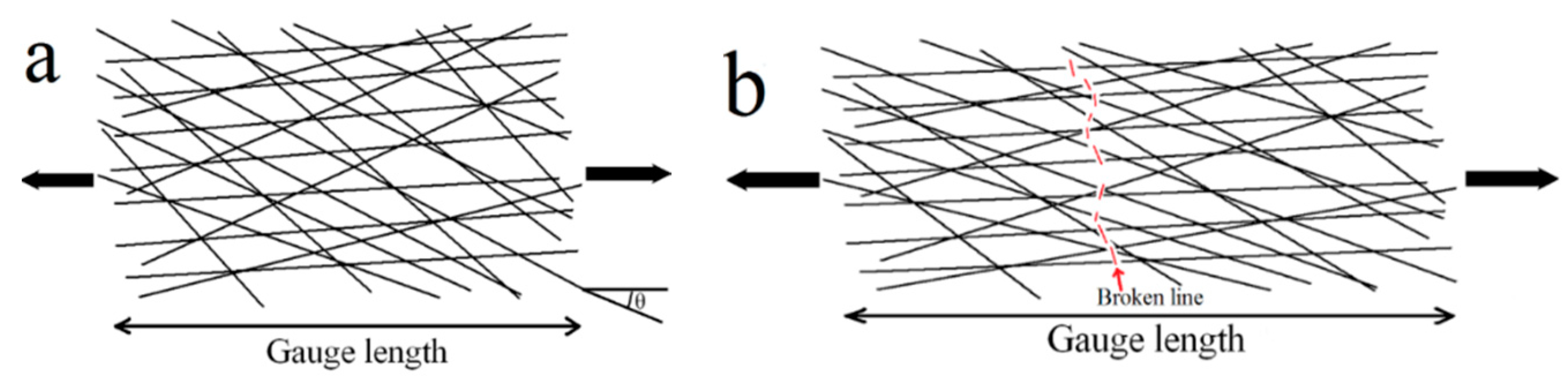
3.1. Tensile Behavior of Sintered 316L SSFF and 316L Stainless Steel Fibers

The exemplary tensile stress–strain curves and the statistical tensile properties of all the sintered 316L SSFFs samples are shown in Figure 3 and Table 2, respectively. The stress-strain curves of all the samples are close to bilinear shape. The plastic stage is considerably long, indicating good plastic performance of the sintered 316L SSFFs. However, from the stress-strain curve of sample I, it is clear that the transition from elastic stage to plastic stage is less distinct than for the others, and the plastic stage is not nearly as linear as for the others sample I has the highest ultimate strength (peak stress at stress-strain curve) and lowest elongation (strain at ultimate strength) (see Table 2). With the rise of sintering temperature from 1000 °C to 1200 °C (with a holding of 5 min), the elongations of 316L SSFFs increase considerably from about 9% for sample I to about 15% for sample II, while the ultimate strengths decrease only slightly. The elongations of sample III are very close to those of sample II but the ultimate strengths drop a little. For the samples sintered at 1200 °C for 60–360 min, the ultimate strengths and elongations were very close to one another, at around 17% and 19 MPa respectively. These stable tensile properties over a large range of holding time are beneficial for the manufacturing of large size uniform sintered 316L SSFFs. It seems that the sintering conditions applied here have a relatively small influence on such elastic properties as Young’s modulus (extracted from the linear portion of the elastic stage of the stress-strain curve) and yield strength (at plastic strain of 0.2%). From the tensile stress-strain curves of these samples, it is obvious that increasing the sintering temperature and holding time considerably improve the elongation, at the price of a relatively small drop in the ultimate strength.
The macrographs of the y-z plane of the fractured samples are given in Figure 4. It can be seen that the lengths of fractures (between the red lines) for samples I, II, and III are considerably larger than those for samples VI and VII. The samples sintered under lower temperature or shorter holding time fractured with clear delamination (especially for sample I, in which the delamination region expanded across a large part of the gauge). While samples VI and VII fractured with far less delamination. The continual decrease of delamination could be caused by the rise of inter-fiber bonding strength which results from the rise of sintering temperature or holding time.
The statistic tensile properties and exemplary tensile stress-strain curves of single fibers are shown in Table 3 and Figure 5, respectively. The exemplary stress-strain curves of sintered single fibers exhibit distinct bilinear shapes irrespective of the sintering conditions, whereas the as drawn fibers show no plastic behavior (see Figure 5). The as drawn fibers show much larger ultimate strengths but far smaller elongations than the sintered fibers. The fractured surface of as drawn fiber, as shown in Figure 6a, is a type of brittle fracture, which is due to the large amount of martensite phase formed during the bundle drawing process [17]. The martensite phase could transform to the austenite phase in the following high temperature sintering process, causing significant “softening” of fibers, as shown in the tensile performance of sample I. The ultimate strength of a single fiber considerably decreases with the rise of temperature from 1000 °C to 1200 °C (see sample I and sample II in Table 3). For the fibers sintered at 1200 °C, the ultimate strengths of fibers decrease a little when the holding time increases from 5 min to 20 min, and then fluctuate around 300 MPa for longer holding times, as shown in Table 3. The fracture surfaces of the sintered fibers show clear necking, and with the rise of sintering temperature and holding time the fiber surfaces become smoother (see Figure 6b–d) due to the diffusion process of the atoms activated by the gradient of the fiber surface curvatures. The elongation of a single fiber seems independent of the sintering conditions. It is obvious that the trends in ultimate strength and elongation of sintered 316L SSFFs are not the same as those of single fibers. The average of the ultimate strengths of single fibers is 470 MPa for sample I, but is 290 MPa for sample VII, only 61.7% of the former. By contrast, the averages of the ultimate strengths for the two corresponding sintered 316L SSFF samples are 22.44 MPa and 20.3 MPa respectively. The close values of ultimate strength between the two SSFFs samples in spite of their large variation in single fiber strength could be explained as following: at the points of peak stress of 316L SSFFs, there were many more fibers burdening the stress at the same time in sample VII than in I, which then compensated for the much lower ultimate strength of a single fiber in sample VII. The continual increase in the elongations of the sintered 316L SSFFs in spite of little variation in single fiber elongations can also be attributed to the fact that in samples from I to VII there are an increasing number of fibers involved in the tensile deformations.
The optical micrographs of fiber grains in the sintered samples are presented in Figure 7. The grains in sample I are much smaller than those in the samples sintered at 1200 °C and are not directly across the fiber sections. While even with a minus holding time of 5 min at 1200 °C, some grains occupied the whole fiber section (see Figure 7b). The continual increase in the average grain size from sample I to sample III by large increments is in accordance with the continual drop of the fiber strength from sample I to sample III (see Table 3). With further increase of the holding time from 20 min to 360 min, the growth of grains is no longer evident, as demonstrated in Table 3 and Figure 7c–e, which could be attributed to the fact that when the grains grow and occupy the full transverse section of fibers, the straight “bamboo like” grain boundaries (marked by red arrows in Figure 7c–e) are hard to move, then hindering further growth of the grains. The indistinctive variation in fiber grain size of samples from III to VII resulted in a relative small variation in their fiber strengths, as shown in Table 3. Apparently these “bamboo like” coarse grains do not result in degradation in the tensile properties of sintered 316L SSFFs (see Figure 3). This observation is opposite to the assertion in the literature [16]. There are grain boundaries distributed between the two edges of the inter-fiber joints (see Figure 7), which could affect the local stress distribution near the joints because the grain boundaries are a hard phase in comparison to the grains.

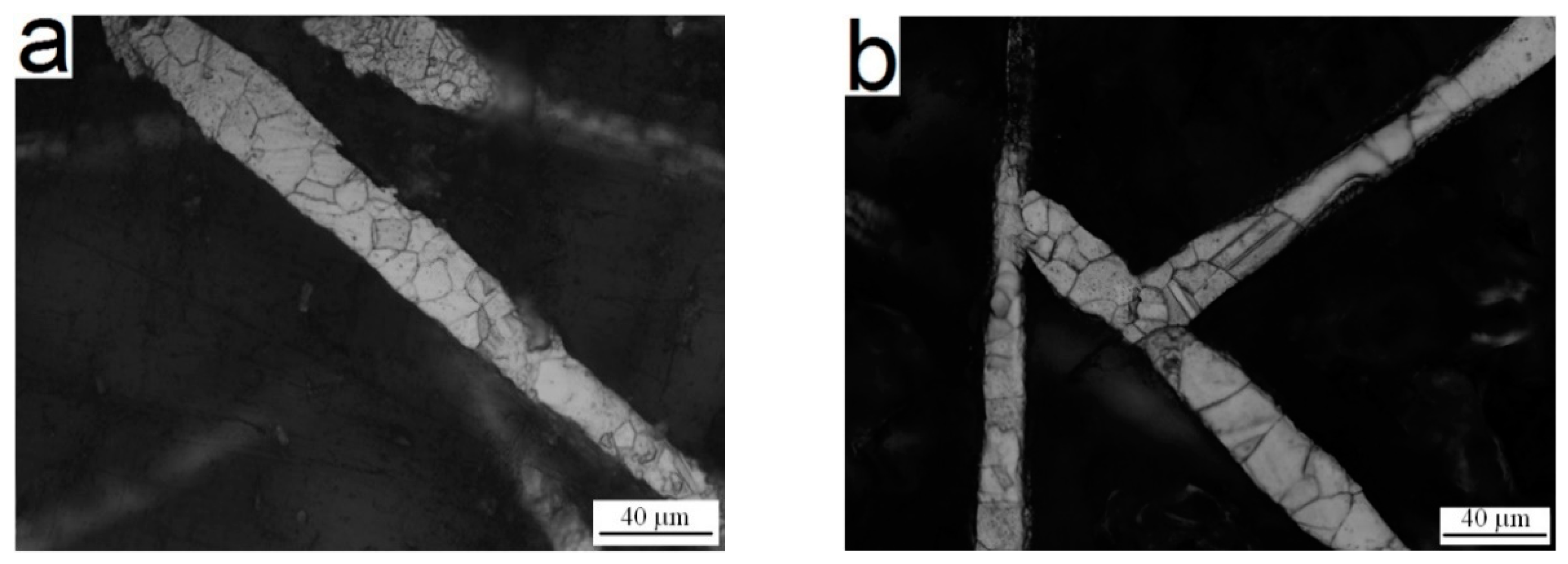
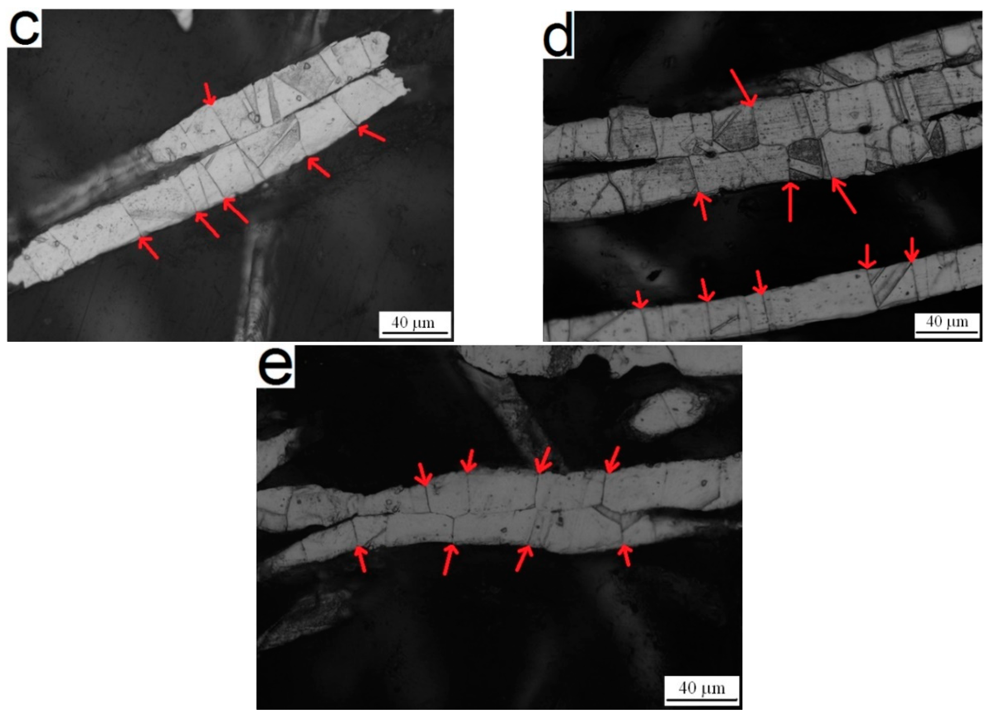
3.2. Effect of Sintering Conditions upon Sintering Joints

In general, a bigger inter-fiber joint neck can provide a stronger bonding strength between fibers. Strong inter-fiber joints can facilitate stress transfer between fibers, bringing more fibers into the fully tensile deformation as analyzed in Section 3.1. Thus, stronger sintering joints can result in larger tensile elongation and tensile strength. So it is important to obtain the size of the sintering joints in 316L SSFFs. The change of measured sintering joint neck size in term of sintering conditions is summarized in Table 4. The neck size varies over large ranges for all the samples, which could be attributed to the irregular shape of the fibers. The sizes of inter-fiber necks for samples from I to VII continually increase according to measurements from the CT images. When the holding time further increases from 240 min for sample VI to 360 min for sample VII, the sintering neck sizes drop a little (see Table 4), which could be attributed to the diversity of the CT samples. The increase in tensile elongation for 316L SSFFs sample from I to IV (see Figure 3 and Table 2) could be attributed to the increase in joint sizes. The increase in joint neck sizes in these samples from I to VII also helps to prevent the ultimate strength of these 316L SSFFs samples from a severe drop as with the trend on the ultimate strength of single fibers (see Table 2 and Table 3). These different trends are discussed in Section 3.1. Furthermore, though the average strengths of single fibers for samples from IV to VII are close to one another, the ultimate tensile strengths of the corresponding sintered 316L SSFFs still increase a little (see Figure 3 and Table 2), which could be caused by the further increase of inter-fiber neck size for the samples from IV to VII.

3.3. Fracture Energy

The measured fracture energy of a single fiber or sintered 316L SSFFs can be calculated based on the area covered by the tensile stress-strain curve. Markaki et al. [3] initially proposed a micro-model for tensile deformation of the fiber network to correlate the fracture energy of single fiber to the fracture energy of sintered 316L SSFFs. To simplify the deduction process they confined the model to the deformation of the gauge part only close to the fractured region. Here we extend the model as valid for the full gauge length of the sample, because it is obvious that the tensile fracture energy of sintered 316L SSFFs is associated with plastic deformation of all the fibers within the gauge, and not confined to deformation of the fibers near the fractured region (see Figure 8).
The calculating formula (adapted from the corresponding formula given in [3]) is given as following:
G fr = [ 4 f cos θ π d 2 ] U s
where Gfr is the fracture energy of sintered 316L SSFFs per unit volume; f is the relative density of sintered 316L SSFFs; θ is the average angle between fiber orientation and the tensile direction; d is the fiber diameter; Us is the measured fracture energy of single fiber per unit length; the formula in the large bracket as a whole represents the number of fibers per unit volume of sintered 316L SSFFs.
For sintered 316L SSFFs samples investigated here, the orientation of fibers in the in-plane directions distributes randomly, so θ is averaged at 45°. The calculated values and measured values of Gfr for samples I, II, and VII are shown in Table 5. The calculated Gfr are of the same order as the measured Gfr, confirming the assumption mentioned above. However their trends with variation of sintering conditions are different from one another. Samples II and VII have much higher measured Gfr than sample I, despite the highest calculated Gfr of I among the three samples. This may be due to the fact that in sample I there are more weak sintering joints than in sample II and sample VII. These weak joints could fail very early during the tensile tests, preventing a number of fibers from being effectively involved in the tensile deformation, as a result the measured Gfr of sample I became lower, despite of having the highest Us of the three samples. For sample VII the measured Gfr and calculated Gfr are very close, indicating that nearly all fibers within the gauge effectively participated in the tensile processes. Neelakantan et al. [13] suggested that by increasing the fracture energy of a single fiber the fracture energy of sintered 316L SSFFs can be improved, but here we can see that to fully utilize the fracture energy of fibers, the strength of the sintering joints must be sufficiently high.

3.4. Fatigue Tensile Behavior of 316L SSFFs

The accumulated strain ε versus the number of cycles N is plotted in Figure 9a–c. Similar to fatigue in metal foams [18], the tension-tension fatigue processes of sintered 316L SSFFs can be divided into three stages: initial stage, stable incubation stage, rapid failure stage. The fatigue lives of 316L SSFFs are sensitive to normalized maximal stresses σmax/σUTS. With a decrease of σmax/σUTS, the fatigued lives increase exponentially.
The measured S-N curves of 316L SSFF samples are plotted in Figure 9c. Though sample II and sample VII have close monotonic tensile properties, their normalized fatigue limits, defined by the ratio σmaxUTS at a fatigue life of 107 cycles, are very different (equal to 0.32 and 0.54 respectively). It can be seen that the sintering condition of 316L SSFF significantly influences their normalized tension fatigue limits.
Under every similar normalized maximal stress σmax/σUTS, sample II exhibits a far shorter fatigue life than sample VII, which may result from the difference in strength of the sintering joints and fiber ligaments between sample II and sample VII. Sample II has relative “stocky” fiber ligaments and “weak” sintering joints, leading to a severe stress concentration in the sintering joints during the tension process. As a result, the fatigue failure in the sintering joints may take place earlier than that of fiber ligaments, leading to shorter fatigue lives of sample II. From Figure 11a, it can be seen that the fractured surface of sample II takes the mode of clear delamination, due to the initial fatigue breakages in the sintering joints as shown in Figure 11b,c. In contrast, not the fatigue failures but the tensile fractures in the fiber ligaments (caused by final sudden breakage of samples in the third stage of the fatigue process) are frequently observed in this sample. In sample VII, the strengths of the sintering joints and fiber ligament are more a match to each other, leading to less stress concentration during the fatigue process. Thus in the sample, the strong sintering joints can withstand the fatigue load throughout the cyclic process, then the fiber ligaments can more effectively bear the fatigue load, resulting in much longer fatigue lives. In Figure 11d, the fracture surface of sample VII shows almost no delamination. Evident fatigue failures in fiber ligaments are observed in Figure 11e,f. In contrast, the fatigue failures in sintering joints are seldom observed in sample VII. Here we can assert that to effectively raise the fatigue life of 316L SSFF, there should be as many fiber ligaments involved in the fatigue process as possible, which is exactly the situation occurring in sample VII.

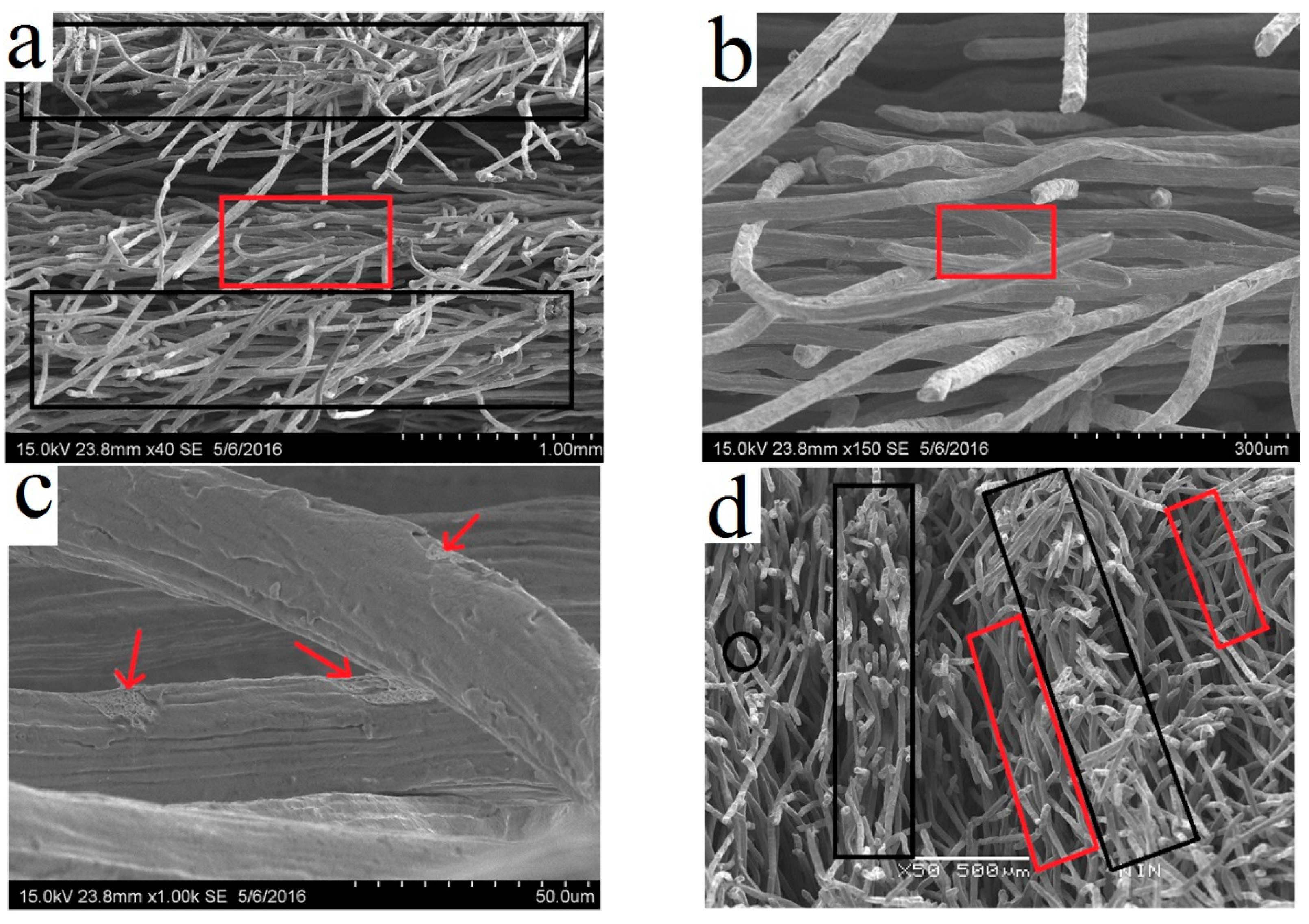
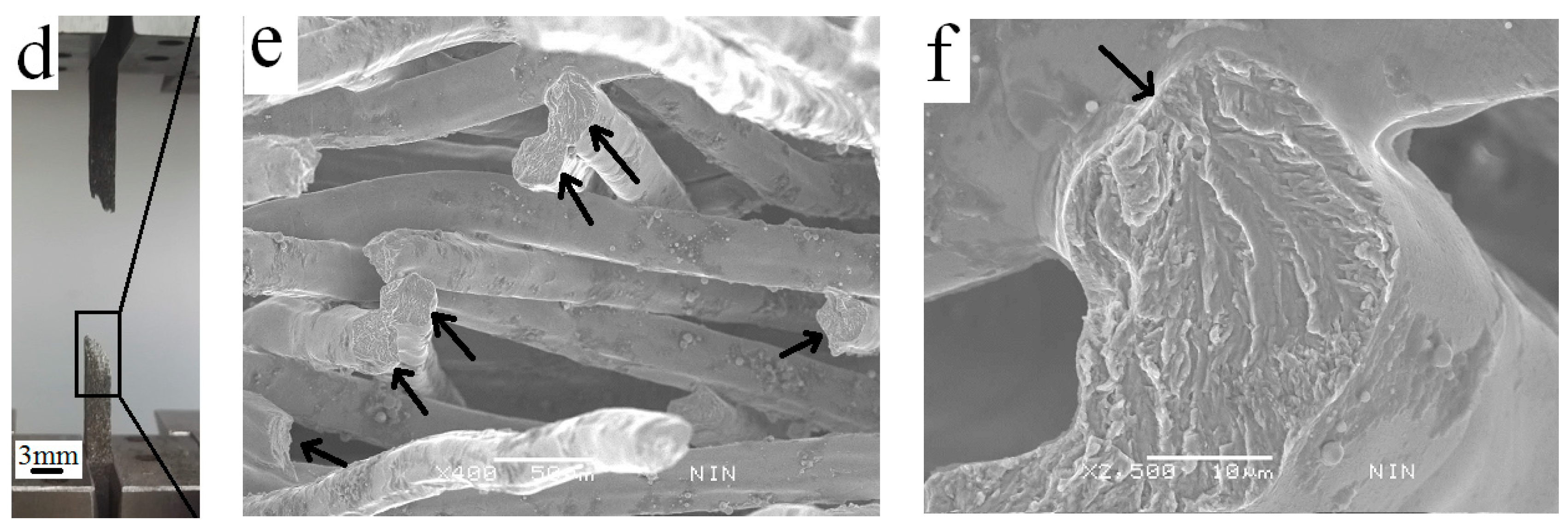
3.5. Fracture Morphology

Figure 10 demonstrates the fractured surface of monotonic tensile samples I and VI. Two kinds of fractures are observed in the samples. One fracture is mainly at the fractured surfaces roughly perpendicular to the load direction, marked by the black boxes in Figure 10a,d,e. In these regions, the fiber grains near the fractured ends experience severe plastic deformation prior to failure and show tortuous and drape morphology (see Figure 10h). The necking of fibers is distinct for this kind of fracture. Allowing for the location and morphology of this kind of fracture it can be inferred that these fibers were subjected to normal tensile stress during the loading processes. Another kind of fracture is located at the delamination surfaces roughly parallel to the load direction, marked by the red boxes in Figure 10a,b,d,e. The fractures at these surfaces are located either at sintering joints or at fiber ligaments close to the sintering joints, depending on the sintering conditions of 316L SSFF. For sample I, fractures are mainly located at the sintering joints because the joints are considerably weaker than the fiber ligaments. Typical examples are shown in Figure 10c,g. With the increase of average size of joints, the locations of the fractures change to fiber ligaments, as shown in Figure 10f for sample VI. This trend could be enhanced by the existence of grain boundaries at the sintering joints which are of tougher phase than the grains and lead to the tendency to fracture beyond the joints, especially when the grains at the fiber ligaments are very large, as for the cases shown in Figure 7c–e. We believe that this kind of fracture was caused by shear stress. This kind of fracture causes delamination between fiber layers in the sintered 316L SSFFs, and contributes little to the macroscopic fracture energy Gfr. With the growth of bonding strength between fibers, the second kind of fracture gradually decreases, as shown in the macrographs of the y-z plane of the fractured samples (Figure 4).
Figure 11 shows the fractured surface of fatigue tensile samples II and VII. In sample II, the fractured sintering joints (marked by black arrows in Figure 11b) exhibit smooth surfaces, which have been squeezed or rubbed during cyclic loading. Fatigue striations are also observed (marked by black arrows in Figure 11c). In sample VII, the fractured fibers (marked by black arrows in Figure 11e) show no necking and many fibers fractured at locations near the sintering joints which are intact. The typical rivers or radial patterns indicate the direction of damage propagation (from the joint region marked bythe black arrow to the bottom of the fractured section in Figure 11f).

4. Conclusions

In this paper we systematically investigated the effect of sintering joints and fiber ligaments on the tensile behavior of sintered 316L SSFFs. A series of conclusions can be drawn as follows:
(1).
With the initial rise of sintering temperature and holding time from I (1000 °C × 10 min) to III (1200 °C × 20 min), the strength of single fibers continually drops due to the coarsening of the fiber grains. Upon further increase in holding time from IV (1200 °C × 60 min) to VII (1200 °C × 360 min), there is no evident decrease of strength of the single fibers observed, due to the very weak further growth of the fiber grains.
(2).
The neck size of the sintering joints varies throughout the samples, but in general its average value increases with the rise of sintering temperature and holding time. The rise of size of the sintering joints results in more fibers being involved in tensile loading, which considerably improves tensile elongation, and prevents the ultimate tensile strength of 316L SSFFs from a severe drop, which could be the result of a severe drop of fiber-ligaments strength in 316L SSFFs caused by the rise of sintering temperature and holding time.
(3).
The measured fracture energies of sintered 316L SSFFs generally increase with the growth of the sintering joint size, even though the fracture energies of single fibers drop. To fully utilize the fracture energy of fibers, the strength of the sintering joints must be sufficiently strong.
(4).
For the 316L SSFFs, the normalized tensile fatigue limit can be increased considerably by raising the holding time during the sintering process. With the same porosity, the normalized fatigue limit of samples with stronger sintering joints is far higher than that of samples with weaker sintering joints.

Author Contributions

Investigation and Writing—Original Draft Preparation, J.M.; Conceptualization, J.M. and Q.Z.; Writing—Review & Editing, Q.Z.; Validation, J.W.; Funding Acquizition, W.S.; Supervision, H.T. and F.J.

Funding

This research was funded by National Nature Science Foundation of China grant number [51701164], and Opening Project of State Key Laboratory of Explosion Science and Technology grant number [KFJJ17-14M].

Acknowledgments

This research was funded by the National Nature Science Foundation of China (No. 51701164), the Opening Project of State Key Laboratory of Explosion Science and Technology (KFJJ17-14M) and the National Key Research and Development Program of China (No. 2016YFB0600100).

Conflicts of Interest

The authors declare no conflict of interest.

References

  1. Lefebvre, L.P.; Banhart, J.; Dunand, D.C. Porous metals and metallic foams: Current status and recent developments. Adv. Eng. Mater. 2008, 10, 775–787. [Google Scholar] [CrossRef] [Green Version]
  2. Markaki, A.E.; Clyne, T.W. Mechanics of thin ultra-light stainless steel sandwich sheet material: Part I. Stiffness. Acta Mater. 2003, 51, 1341–1350. [Google Scholar] [CrossRef]
  3. Markaki, A.E.; Clyne, T.W. Mechanics of thin ultra-light stainless steel sandwich sheet material: Part II. Resistance to delamination. Acta Mater. 2003, 51, 1351–1357. [Google Scholar] [CrossRef]
  4. Tang, Y.; Zhou, W.; Pan, M.; Chen, H.; Liu, H.; Yu, H. Porous copper fiber sintered felts: An innovative catalyst support of methanol steam reformer for hydrogen production. Int. J. Hydrogen Energy 2008, 33, 2950–2956. [Google Scholar] [CrossRef]
  5. Markaki, A.E.; Clyne, T.W. Magneto-mechanical stimulation of bone growth in a bonded array of ferromagnetic fibres. Biomaterials 2004, 25, 4805–4815. [Google Scholar] [CrossRef] [PubMed]
  6. VerSys Epoch Full Coat Hip Prosthesis. Available online: http://www.zimmer.com/en-US/hcp/hip/product/versys-epoch-fullcoat.jspx (accessed on 10 August 2018).
  7. Liu, Y.; Wang, H.; Li, J.; Lu, Y.; Xue, Q.; Chen, J. Microfibrous entrapped Ni/Al2O3 using SS-316 fibers for H2 production from NH3. AIChE J. 2007, 53, 1845–1849. [Google Scholar] [CrossRef]
  8. Zhi, H.; Tang, H.P.; Zhu, J.L.; Wang, J.Z.; Ao, Q.B.; Ma, J. Preparation Method of Composite Porous Surface with Metal Fiber for Heat Transfer. Chinese Patent CN: ZL201110396522.4, 2 May 2012. [Google Scholar]
  9. Bo, Z.; Tianning, C. Calculation of sound absorption characteristics of porous sintered fiber metal. Appl. Acoust. 2009, 70, 337–346. [Google Scholar] [CrossRef]
  10. Zhao, T.F.; Chen, C.Q. The shear properties and deformation mechanisms of porous metal fiber sintered sheets. Mech. Mater. 2014, 70, 33–40. [Google Scholar] [CrossRef]
  11. Tsarouchas, D.; Markaki, A.E. Extraction of fibre network architecture by X-ray tomography and prediction of elastic properties using an affine analytical model. Acta Mater. 2011, 59, 6989–7002. [Google Scholar] [CrossRef]
  12. Zhao, T.F.; Chen, C.Q.; Deng, Z.C. Elastoplastic properties of transversely isotropic sintered metal fiber sheets. Adv. Mater. Sci. Eng. A 2016, 662, 308–319. [Google Scholar] [CrossRef]
  13. Neelakantan, S.; Bosbach, W.; Woodhouse, J.; Markaki, A.E. Characterization and deformation response of orthotropic fibre networks with auxetic out-of-plane behaviour. Acta Mater. 2014, 66, 326–339. [Google Scholar] [CrossRef]
  14. Zhou, W.; Tang, Y.; Pan, M.; Wei, X.; Xiang, J. Experimental investigation on uniaxial tensile properties of high-porosity metal fiber sintered sheet. Mater. Sci. Eng. A 2009, 525, 133–137. [Google Scholar] [CrossRef]
  15. Liu, H.L.; Wang, J.Z.; Tang, H.P. Study on tensile property of sintered metal fiber felts. Rare Met. Mater. Eng. 2014, 14, 2023–2029. [Google Scholar]
  16. Ma, J.; Li, A.; Tang, H. Study on sintering mechanism of stainless steel fiber felts by X-ray computed tomography. Metals 2016, 6, 18. [Google Scholar] [CrossRef]
  17. Shyr, T.-W.; Shie, J.-W.; Huang, S.-J.; Yang, S.-T.; Hwang, W.-S. Phase transformation of 316L stainless steel from wire to fiber. Mater. Chem. Phys. 2010, 122, 273–277. [Google Scholar] [CrossRef]
  18. Kolluri, M.; Mukherjee, M.; Garcia-Moreno, F.; Banhart, J.; Ramamurty, U. Fatigue of a laterally constrained closed cell aluminum foam. Acta Mater. 2008, 56, 1114–1125. [Google Scholar] [CrossRef]
Figure 1. (a) Green 316L stainless steel fiber felts (SSFFs) compact (un-pressed) in steel mold; (b) schematics and photograph of 316L SSFF tensile sample.
Metals 08 00768 g001
Figure 2. Measurement of neck radius of sintering joints from the computed tomography (CT) image of sintered 316L SSFFs.
Metals 08 00768 g002
Figure 3. Tensile stress–strain curves for 316L SSFFs samples.
Metals 08 00768 g003
Figure 4. Macrograph of y-z plane of the fractured samples.
Metals 08 00768 g004
Figure 5. Tensile stress-strain curves of single fibers.
Metals 08 00768 g005
Figure 6. Fracture surfaces of single fiber of (a) as drawn; (b) sample I; (c) sample II; (d) sample VII.
Metals 08 00768 g006
Figure 7. Optical micrographs of sample (a) I; (b) II; (c) III; (d) VI; (e) VII.
Metals 08 00768 g007aMetals 08 00768 g007b
Figure 8. Schematic representations of the micro-model for the fiber network: (a) before tensile deformation; (b) after tensile break, in which state every single fiber experiences plastic deformation and is elongated, contributing to the accumulation of fracture energy of sintered 316L SSFFs.
Metals 08 00768 g008
Figure 9. The accumulated strain ε versus number of cycles N of (a) sample II, (b) sample VII and, (c) the measured S-N (Nomalized maximum stress-Number of cycles) curves of samples II and VII under cyclic tension-tension loading.
Metals 08 00768 g009
Figure 10. Fracture surfaces of tensile samples of 316L SSFFs (a) I, area of two kinds fractures; (b) I, enlarged area of delamination in (a); (c) I, enlarged area in the red box in (b); (d) VI, area of two kinds fractures; (e) VI, enlarged area of delamination in (d); (f) VI, enlarged area in the red box in (e); (g) I, joint breakage at area of delamination; (h) VI, fiber breakage subjected to normal stress, enlarged area in the black circle in (d).
Metals 08 00768 g010aMetals 08 00768 g010b
Figure 11. Fatigue failure mode of sample II (ac), and sample VII (df).
Metals 08 00768 g011aMetals 08 00768 g011b
Table 1. 316L stainless steel fiber felts (SSFFs) fabricated at different sintering parameters.
SampleSintering Temperature (°C)Holding Time (min)Porosity (%)
I10001082.7 ± 0.24
II1200582.8 ± 0.14
III12002082.5 ± 0.18
IV12006082.7 ± 0.20
V120012082.6 ± 0.24
VI120024082.3 ± 0.09
VII120036082.2 ± 0.04
Table 2. Tensile property of 316L SSFFs samples.
ConditionsYoung’s Modulus (GPa)Yield Strength σ0.2 (MPa)Ultimate Strength (MPa)Elongation (%)
I, 1000 °C × 10 min3.68 ± 0.149.50 ± 0.0622.44 ± 0.429.0 ± 0.9
II, 1200 °C × 5 min3.38 ± 0.099.82 ± 0.7622.06 ± 0.4214.9 ± 0.5
III, 1200 °C × 20 min3.67 ± 0.069.53 ± 0.0720.34 ± 0.3215.5 ± 0.8
IV, 1200 °C × 60 min3.62 ± 0.099.44 ± 0.1218.68 ± 0.4517.4 ± 0.4
V, 1200 °C × 120 min3.68 ± 0.139.52 ± 0.1318.71 ± 0.3917.6 ± 0.7
VI, 1200 °C × 240 min4.20 ± 0.0510.2 ± 0.1119.85 ± 0.3117.0 ± 0.8
VII, 1200 °C × 360 min4.05 ± 0.099.85 ± 0.1120.30 ± 0.3717.2 ± 0.5
Table 3. Tensile properties of single fibers and average transverse size of fiber grains.
SampleUltimate Strength (MPa)Elongation (%)Average Grain Transverse Size (µm)
As drawn1330 ± 2521.18 ± 0.25-
I, 1000 °C × 10 min470.0 ± 7711.4 ± 3.810.9
II, 1200 °C × 5 min360.0 ± 5212.4 ± 3.4616.8
III, 1200 °C × 20 min280.0 ± 5112.3 ± 3.920.2
IV, 1200 °C × 60 min320.0 ± 4313.2 ± 3.222.2
V, 1200 °C × 120 min290.0 ± 5011.3 ± 3.722.8
VI, 1200 °C × 240 min310.0 ± 519.4 ± 3.122.3
VII, 1200 °C × 360 min290.0 ± 4710.9 ± 3.622.4
Table 4. Average neck size of sintering joints in different CT samples.
Sintering ConditionsNeck Size (µm)
I, 1000 °C × 10 min8.1 ± 7.0
II, 1200 °C × 5 min13.3 ± 6.4
III, 1200 °C × 20 min19.9 ± 7.0
IV, 1200 °C × 60 min20.4 ± 7.6
V, 1200 °C × 120 min23.5 ± 8.1
VI, 1200 °C × 240 min25.2 ± 7.6
VII, 1200 °C × 360 min24.6 ± 5.6
Table 5. Fracture energies for sintered 316L SSFFs and single fiber.
SampleMeasured Gfr (J/cm3)Us (J/cm)Calculated Gfr (J/cm3)
I2.48 ± 0.140.00026 ± 0.000065.08 ± 1.17
II3.29 ± 0.110.00018 ± 0.000023.52 ± 0.391
VII3.10 ± 0.070.00015 ± 0.000032.93 ± 0.586

