Article

Effect of High-Pressure Torsion on Structure and Microhardness of Ti/TiB Metal–Matrix Composite

1
Laboratory of Bulk Nanostructured Materials, Belgorod State University, Belgorod 308015, Russia
2
Karlsruhe Institute of Technology, Institute of Nanotechnology, 76021 Karlsruhe, Germany
*
Author to whom correspondence should be addressed.
Metals 2017, 7(11), 507; https://doi.org/10.3390/met7110507
Submission received: 19 October 2017 / Revised: 10 November 2017 / Accepted: 13 November 2017 / Published: 16 November 2017

Abstract

:
Effect of high-pressure torsion (HPT) at 400 °C on microstructure and microhardness of a Ti/TiB metal–matrix composite was studied. The starting material was produced by spark plasma sintering of a mixture of a pure Ti and TiB2 (10 wt %) powders at 1000 °C. The microstructure evolution during HPT was associated with an increase in dislocation density and substructure development that resulted in a gradual microstructure refinement of the Ti matrix and shortening/redistribution of TiB whiskers. After five revolutions, a nanostructure with (sub) grain size of ~30 nm was produced in Ti matrix. The microhardness increased with strain attaining the value ~520 HV after five revolutions. The contribution of different hardening mechanisms into the hardness of the Ti/TiB metal–matrix composite was quantitatively analyzed.

Graphical Abstract

1. Introduction

Due to high strength-to-density ratio, excellent corrosion resistance and good biocompatibility titanium and titanium alloys are attractive for various applications, including the aerospace, automotive, chemical and biomedical industries [1]. However, relatively low strength, hardness and wear resistance limit the application of titanium and low-alloyed titanium alloys. One of the effective methods to improve their strength-related mechanical properties is creating a metal–matrix composite (MMC) by inserting ceramic fibers or particles into the Ti matrix [2,3,4,5,6,7]. In this case, high strength and stiffness of ceramic reinforcements combine with good toughness provided by a metal matrix. Some improvements of wear resistance and high temperature properties of MMCs (metal–matrix composites) can also be expected [6,8,9,10]. Titanium alloys can be reinforced by TiB2, TiN, B4C, ZrC, TiB, TiC, and Al2O3 [6]. Among various reinforcements, TiB seems to be the most attractive option because it has a close to titanium density, high Young’s modulus and reasonable stability at the processing temperatures [11,12]. In addition, TiB creates minimal residual stresses due to similarity of thermal expansion coefficient and good crystallographic interfaces with the titanium matrix [11,12,13]. The effect of TiB on the strength properties of Ti-based matrix was either as good as, if not better than, most widely used reinforcements such as TiC or Al2O3 [7,14].
Fully dense bulk Ti/TiB specimens can be obtained in situ during the spark plasma sintering (SPS) process through the TiB2 + Ti →Ti + 2TiB reaction [13]. The TiB crystals have a whisker-like shape with very small (down to nano-range) diameter [13]. Due to high heating rate and high pressures, consolidation during the SPS occurs at relatively low temperatures and within short time intervals. Therefore, in contrast to many other sintering treatments, noticeable microstructure coarsening can be avoided during the SPS. However, high strength of Ti/TiB MMCs is usually accompanied by low ductility at room temperature [11,15].
Thermomechanical treatment can considerably improve ductility and strength and decrease ductile-to-brittle transition temperature of MMCs [15,16,17,18]. However, the microstructure evolution of MMCs during deformation under different conditions has not been studied comprehensively so far [19]. One of the promising ways to modify the microstructure of metallic materials considerably is severe plastic deformation (SPD) [20], which usually resulted in microstructure refinement to the nanoscale region. Although SPD of various materials by different methods has been a subject of intensive investigations during few last decades [20,21,22], SPD of MMCs was studied insufficiently. Recent studies on the influence of high pressure torsion (HPT) on microstructure and mechanical properties of various MMCs composites, including Ti/Al2O3 and Ti/TiO2 [23,24], have shown that SPD basically resulted in grain refinement of the matrix material, homogeneous distribution of the second phase particles and diminished particle size [25], thereby enhancing both strength and ductility of the MMCs [26]. It should be noted that the majority of known investigations of microstructure evolution during SPD were conducted using MMCs reinforced with carbon-based or oxide particles of nearly equiaxed shape [22,23,24,25,26]. Much less attention was paid to SPD of MMCs reinforced by elongated particles or fibers, such as Ti/TiB. The processing should obviously break the TiB whiskers with high aspect ratio and reduce the grain size of the Ti matrix. However, no information on this topic was found in the literature.
In this work, a Ti/TiB MMC was produced by the spark plasma sintering using a Ti-10 wt % TiB2 powder mixture at a temperature of 1000 °C. Then the sintered composite was subjected to HPT at 400 °C with a number of revolutions in the interval 1–5. Microstructure evolution of the composite was comprehensively (i.e., both Ti matrix and features of TiB whiskers were investigated) studied using SEM (Scanning Electron Microscope) and TEM (Transmission Electron Microscope) and microhardness measurements were used to estimate the effect of HPT on mechanical properties.

2. Materials and Procedure

Commercial Ti powders (wt % of impurities: 0.07 N, 0.05 C, 0.34 H, 0.34 (Fe + Ni) and 0.1 Si; and TiB2 (wt % of impurities: 0.04 O, 0.04 C, 0.02 Fe) were used as the raw materials. In both cases, the particles had an irregular shape; the average particles sizes of the Ti and TiB2 powders were ~25 and ~4 μm, respectively. A mixture of Ti powder with 10 wt % of TiB2 was prepared using a Retsch RS200 vibrating cup mill (RETSCH, Haan, Germany) for 1 h in ethanol at the milling rotation speed of 700 rpm. Specimens of Ti/TiB metal–matrix composite measured 19 mm diameter and 20 mm height were produced through the SPS process under vacuum at 1000 °C and 40 MPa for 5 min using a Thermal Technology SPS10-3 machine (Thermal Technology, LLC, Santa Rosa, CA, USA).
Disks measured 0.7 mm thickness and 10 mm diameter were cut from the Ti/TiB specimens using the electric-discharge machine (Sodick Inc., Schaumburg, IL, USA) and then deformed by HPT in a Bridgman anvil type unit using a custom-built computer-controlled device (Klement GmbH, Lang, Austria) at 400 °C and 6 GPa with a speed of 1 rpm. The number of revolutions was N = 1, 2 or 5. The corresponding shear strain level γ can be calculated as [22]:
γ = 2 π N r h
where N is the number of revolutions, r is the radius and h is the thickness of the specimen. The temperature of deformation was chosen based on preliminary experiments; at lower temperatures the MMC did not possess enough ductility for the SPD treatment.
X-ray diffraction (XRD) analysis was done for the shear plane of specimens using an ARL-Xtra diffractometer (Thermo Fisher Scientific, Portland, OR, USA) with CuKα radiation. The dislocation density was estimated as broadening of XRD peaks using Williamson-Hall method [27]. A JEOL JEM-2100 transmission electron microscope (TEM; JEOL, Tokyo, Japan) and a Quanta 200 scanning electron microscope (SEM; Thermo Fisher Scientific, Portland, OR, USA) were used for microstructure examination. Structure and mechanical properties were studied in the mid-thickness of the specimens in the axial cross-section (using SEM and microhardness) or in the shear plane (using TEM). SEM analysis and microhardness measurements were done at the distance of 0, or ~5 mm from the center; the observation point for TEM was spaced ~1.5 mm from the edge of the disc.
Specimens for SEM analysis were mechanically polished in water with different SiC papers and colloidal silica suspension; the final size of Al2O3 abrasive was 0.05 μm. Etching was carried out with Kroll’s reagent (95% H2O, 3% HNO3, 2% HF). Thin-foil specimens for TEM characterization were prepared by mechanical thinning followed by electropolishing on a twin-jet TENUPOL-5 at 29 V and at −35 °C using an electrolyte containing 60 mL perchloric acid, 600 mL methanol and 360 mL butanol.
Vickers microhardness was determined under a load of 1 kg for 10 s. The reported hardness values were the average of at least 10 measurements.

3. Results

3.1. Initial Microstructure

According to XRD data (Figure 1), the Ti/TiB MMC consisted of hcp (hexagonal close-packed) α-Ti, TiB2 with a hexagonal lattice, and TiB with an orthorhombic lattice. The volume fractions of the phases in the initial condition were 78.6% of Ti, 19% of TiB and 2.4% of TiB2.
The microstructure of Ti/TiB MMC was rather complicated to analyze since there were no obvious links between the images obtained by either optical or scanning electron microscopy in an unetched state using a BSE backscattered electrons; Thermo Fisher Scientific, Portland, OR, USA) detector (Figure 2a) or in an etched state (Figure 2b–e). On the unetched surface, relatively large light particles of different shape and size (5–10 μm) can be seen (Figure 2a). However, in the etched condition, the microstructure of the Ti/TiB MMC consisted of TiB whiskers heterogeneously distributed within the Ti matrix; some residual TiB2 particles were also observed (shown by arrows in Figure 2b). The variation in density of the TiB whiskers and the presence of the remnants of TiB2 particles were seen as dark-gray or light-gray areas on the unetched surface (areas #1–3 in Figure 2a vs. Figure 2b and corresponding enlarged images in Figure 2c–e). The microhardness for areas #1–3 in Figure 2 was found to be 420 ± 15 HV, 580 ± 25 HV and 940 ± 175 HV, respectively; i.e., an increase in density of TiB whiskers resulted in an increase in hardness.
TEM examination also revealed the TiB whiskers heterogeneously distributed in the Ti matrix (Figure 3a). In the majority of the microstructures, a very high dislocation density was observed, probably due to a large number of the TiB particles. Individual grains cannot be distinguished in the microstructure, however the size of areas with relatively low dislocation density (i.e., the space between areas with a large number of the TiB particles and high dislocation density) was ~1–1.5 μm. The TiB whiskers had an irregular hexagonal shape (Figure 3b) with sides parallel to the (100), (101) and ( 10 1 ¯ ) planes [28]. Many stacking faults were observed in the (100) plane of the TiB whisker. Due to the presence of the orientation relationship (OR) between the TiB particles and the Ti matrix (which is usually described as ( 10 1 ¯ 0 )α//(100)TiB and [ 01 1 ¯ 0 ]α//[ 0 1 ¯ 1 ]TiB [29]), the interphase Ti/TiB boundaries are very clear without noticeable internal stresses. The transversal size of the TiB whiskers varied in a wide interval from tens to few hundred nanometers with the average value of 63 ± 35 nm.

3.2. Microstructure Evolution during High-Pressure Torsion

The influence of HPT on the microstructure depended essentially on the distance from the specimen center (Figure 4). In the central part, the microstructure after one revolution of HPT did not change noticeably. At the edge of specimens (γ ≈ 45), a microstructure consisting of dark wavy bands (elongated regions with a different density of the TiB whiskers) and black spots (remnants of TiB2 surrounded by a “brushes” of TiB whiskers, Figure 2b) was revealed (Figure 4a). Quite similar microstructure was observed in the center of specimens after five revolutions (Figure 4b). Severe deformation (γ ≈ 224) achieved at the edge of specimens after five revolutions (Figure 4c,d) formed quite homogeneous microstructure with numerous inclusions of TiB debris of different size.
The apparent length of the whiskers dropped by a factor of ~5.5 during the first revolution of HPT and then decreased slower (by ~55%) while the number of rotation increased from 1 to 5 (Figure 5). The length-to-diameter aspect ratio of the TiB whiskers approached values of ~5 at the final stages HPT. For comparison, in the initial condition the aspect ratio was ~47. It should be noted that XRD analysis (not shown) did not reveal any noticeable changes in the fraction of the constitutive phases.
Meanwhile, TEM analysis showed considerable refinement of the titanium matrix of the composite as a result of HPT (Figure 6a and Figure 7a). Deformation to γ ≈ 31 (1 revolution) resulted in the formation of a cellular microstructure with a very high dislocation density (Figure 7b). Dislocation density measured by XRD increased from 1.2 × 10¹⁵ m−2 in the initial condition to 1.7 × 10¹⁵ m−2 after one revolution. The boundaries of cells were rather wide and diffuse; however, some (sub)grains with clean thin boundaries and reduced dislocation density can also be seen in the microstructure. The average size of cells and (sub)grains was found to be ~90 nm after one revolution of HPT (Figure 7a). The interphase Ti/TiB boundaries were blurred due to high internal stresses caused by the high dislocation density in the vicinity of the interfaces, however no sign of cracks or voids formation along the interfaces was observed.
During further deformation, the microstructure almost did not change qualitatively. However, increase in strain to γ = 62 (two revolutions) and to γ = 157 (five revolutions) decreased the size of cells and (sub)grain to 55 and 34 nm, respectively, and increased dislocation density to 4.0 × 10¹⁵ m−2 and 8.2 × 10¹⁵ m−2, respectively (Figure 6b,c and Figure 7).

3.3. Microhardness

Figure 8a shows the microhardness evolution at the center and the edge of the disks during HPT. The microhardness at the edge of the specimen increased with strain more intensively than that in the center. The maximum microhardness attained after five revolutions (γ ≈ 224) was ~510 HV and 485 HV at the edge and in the center, respectively. Both values were higher than those in the initial condition; however, the increment did not exceed 10%. In comparison with the microhardness of commercially pure titanium (Ti of 99.4% purity) subjected to HTP at room temperature (~300 HV [30]), the reinforcement with TiB particles and further particles refinement due to HPT yield ~80% hardening. It should be noted that the difference in hardness between the center and edge of the specimen increased during HPT. Usually the hardness of the center of specimens “caught up” the hardness of the edge after a certain strain [22]. However, in our case, five revolutions did not result in hardness saturation at the edge of the specimen yet; that is why hardening in the center occurred slower.

4. Discussion

The results of the present work show considerable changes in microstructure as a result of one to five revolutions during HPT at 400 °C. The main changes were associated with the formation of a nanostructure in the titanium matrix and refinement/redistribution of the TiB particles. However, it should be noted that the microstructure was highly heterogeneous through the specimen; in the center of the discs, the microstructure remained moderately deformed even after five revolutions (Figure 3b). This is an obvious result of a strong gradient of the imposed strain along the radius of the discs (see Equation (1)) and is typical of the HPT process [22].
Formation of a nanocrystalline microstructure after HPT is well documented for various metallic materials [22] including MMCs with different matrixes and reinforcements [22]. The microstructure evolution during HPT at room temperature is usually associated with the formation of low-angle grain boundaries at low strains and transformation of some of these low-angle subgrain boundaries into high-angle grain boundaries at higher strains giving rise to a considerable microstructure refinement. Hughes and Hansen [31] ascribed this process to gradual transformation of geometrically necessary boundaries, which separate microvolumes with different combinations of slip systems, from low-angle subboundaries into high-angle grain boundaries. At elevated temperatures due to the development of thermoactivated processes such a fragmented structure can transform into grain one through continuous dynamic recrystallization (cDRX). In the investigated composite, cDRX was found to operate during uniaxial compression at 700 °C [19]. Therefore, the formation of new very small (34–90 nm, Figure 7a) grains with relatively low dislocation density and well-defined boundaries (Figure 6) during HPT at 400 °C can also be attributed to the occurrence of cDRX. It worth noting that the grain size attained in the commercial pure titanium (Grade 4) during HPT at the same temperature was found to be much larger (approximately 250 nm) [29]. The formation of very small grains in the Ti/TiB MMCs during HPT can be associated with a higly constrained deformation due to the present of a large number of TiB whiskers and very high dislocation density in the initial condition. All these factors resulted in higher flow stress of the composite in comparison with that of commercial pure titanium. Since the size of recrystallized grains (D) depends on the flow stress (σs) as σs = KDN, where K and N are constants [32], an increase in flow stress during deformation should lead to the formation of much smaller recrystallized grains, which is in agreement with the obtained result.
Another effect of severe plastic deformation on the microstructure of Ti/TiB MMC was a considerable (by ~6 times) decrease in the length of the TiB whiskers. This change occurred in the very beginning of the HPT (Figure 4); further straining resulted in more homogeneous redistribution of the TiB particles in the Ti matrix. The latter effect was mentioned by Bachmaier and Pippan [25] with respect to various MMCs.
More interesting is to consider the effect of the observed features on mechanical properties. The microstructural changes occurring during HPT were accompanied by a noticeable rise in hardness (Figure 8a). The contributions of the most relevant hardening mechanisms in hardness of the composite can be expressed as:
H V Σ   =   H V 0   +   H V ρ   +   H V H P +   H V TiB
where H V 0 denotes the friction stress, H V ρ is the substructure hardening, H V H P is the Hall–Petch hardening and H V TiB is the precepetation hardening by debris of TiB.
The substructure hardening H V ρ can be expressed as:
H V ρ   =   M α G b ρ
where M is the average Taylor factor, α is a constant, G is the shear modulus, b is the Burgers vector and ρ is the dislocation density. Typical values of M and α accepted for approximate calculations are 3 and 0.5, respectively. The Hall–Petch contribution to the strength is typically of the form:
H V H P   =   K y   d 1 2
where Ky is the Hall–Petch coefficient and d is the grain size. The precipitation hardening H V TiB (Orowan strengthening) can be calculated using the formula [33]:
H V TiB = M G b 2.36 π ln ( 0.57 D S 1 3 b ) 1 ( 0.92. V 1 3     1.14 ) D S 1 3
where D is the diameter of TiB whiskers, V is the volume fraction of TiB, and S is aspect ratio of TiB whiskers.
Some input parameters for the titanium matrix were taken from [34]: Ky = 0.3 MPa·m1/2, HV0 = 496 MPa and b = 2.9 × 10⁻¹⁰ m. The value of the shear stress G = 130 GPа for the Ti/TiB MMC was taken from [11]. The grain size d, dislocation density ρ, and particles diameter X were taken from Figure 4 and Figure 6a,b, respectively. The volume fraction of TiB determined using X-ray analysis was 19%.
In the case of composite materials, some contribution to the total strength can also be expected from [5]: (i) solid solution strengthening by precipitation of interstitial carbon, oxygen and nitrogen atoms in the Ti lattice; (ii) prismatic punching of dislocations at the Ti/TiB interface due to thermal mismatch between the Ti and TiB; and (iii) load transfer from the Ti matrix to TiB by an interfacial shear stress. The total strengthening effect by interstitial C, O and N atoms in titanium, according to Ref. [35], was found to be 160 MPa (this value was included into HV0). The solubility of boron in titanium is very low (<0.001 at %) [6] therefore the effect of boron atoms on strengthening was neglected. Due to very small difference in coefficient of thermal expansions between Ti and TiB the effect of prismatic punching of dislocations at Ti/TiB interface on strength was too small to mention. According to Refs. [33,36], the effect of load transfer is much lower than that of Orowan strengthening for the aspect ratio smaller than 10 (in our case ~5) so that this factor was also not taken into account.
The calculated contributions of different hardening mechanisms into the total hardness are shown in Figure 8b. It is seen that the Hall–Petch hardening has the lowest effect on strength. Substructure hardening gives a somewhat higher contribution. The contribution of these two hardening mechanisms expectably increased with strain due to the microstructure refinement and increase in dislocation density (Figure 7). Meanwhile, hardening due to the TiB precipitates gives a much more pronounced effect which is more than twice of that for the combined effect of Hall–Petch and substructure hardenings. Precipitation hardening also increased during deformation due to shortening of the reinforcements (Figure 5). More homogeneous distribution of the TiB particles can also give some effect in the mechanical properties, however more likely it can result in an increase in ductility [16,17,22] rather than in a pronounced strengthening.
The overall effect of various strengthening mechanisms fits well with the experimental result, suggesting that the precipitation hardening contribution is much more important than the substructure and Hall–Petch hardenings. Therefore, the properties of MMCs are most probably associated with the morphology and distribution of reinforcements rather than with the properties of the matrix. This statement is in agreement with a number of investigations on the contribution of various strengthening mechanisms after SPD. In various precipitation-hardened alloys (Al-Mg-Sc [37], Cu-Cr-Zr [38] or Mg-Y-Nd-Zr [39]), the effect of Orowan strengthening was equal to or higher than the total contribution of grain-size and substructure strengthenings.
An attractive application of Ti/TiB MMCs with high hardness can be associated with production of medical instruments, in particular cutting tools, because this material has some undeniable advantages over the “medical” steel: possibility of application in a magnetic field, low specific gravity and high biocompatibility.

5. Conclusions

Microstructure evolution and microhardness of Ti/TiB metal–matrix composite were studied during high-pressure torsion (HPT) at 400 °C. The following conclusions were made:
(1)
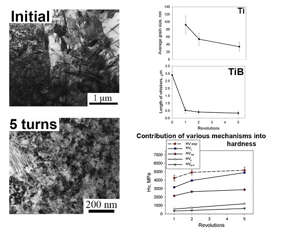
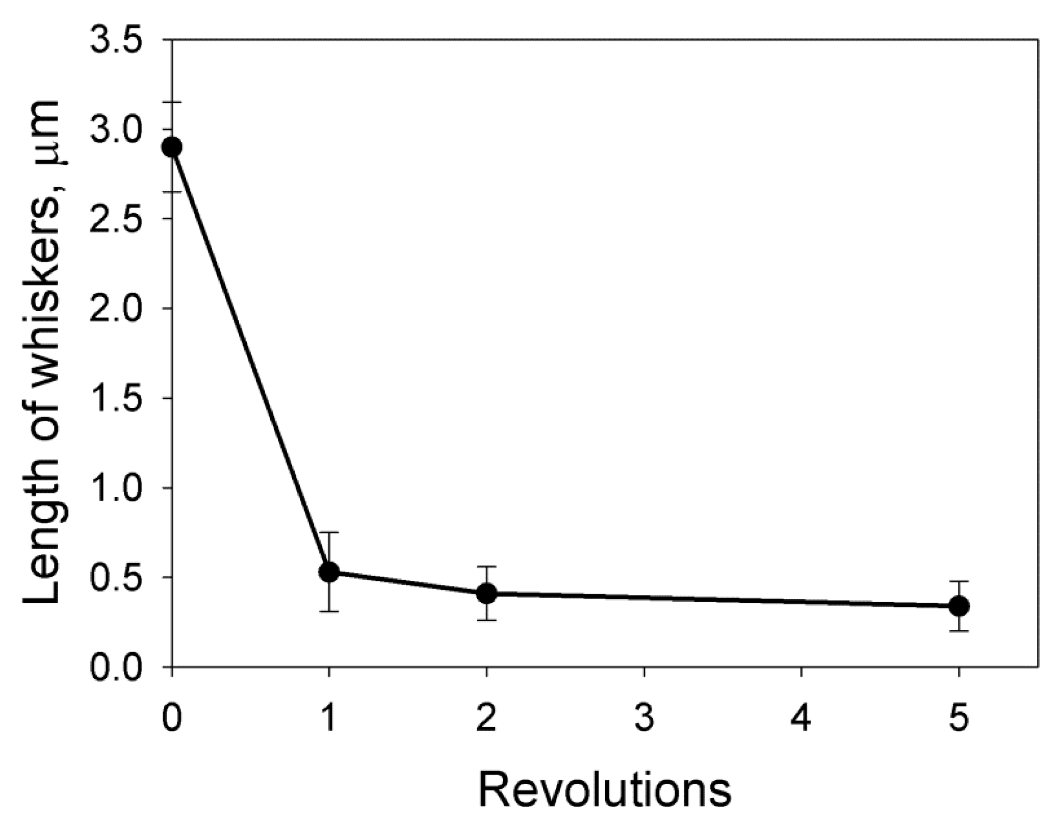
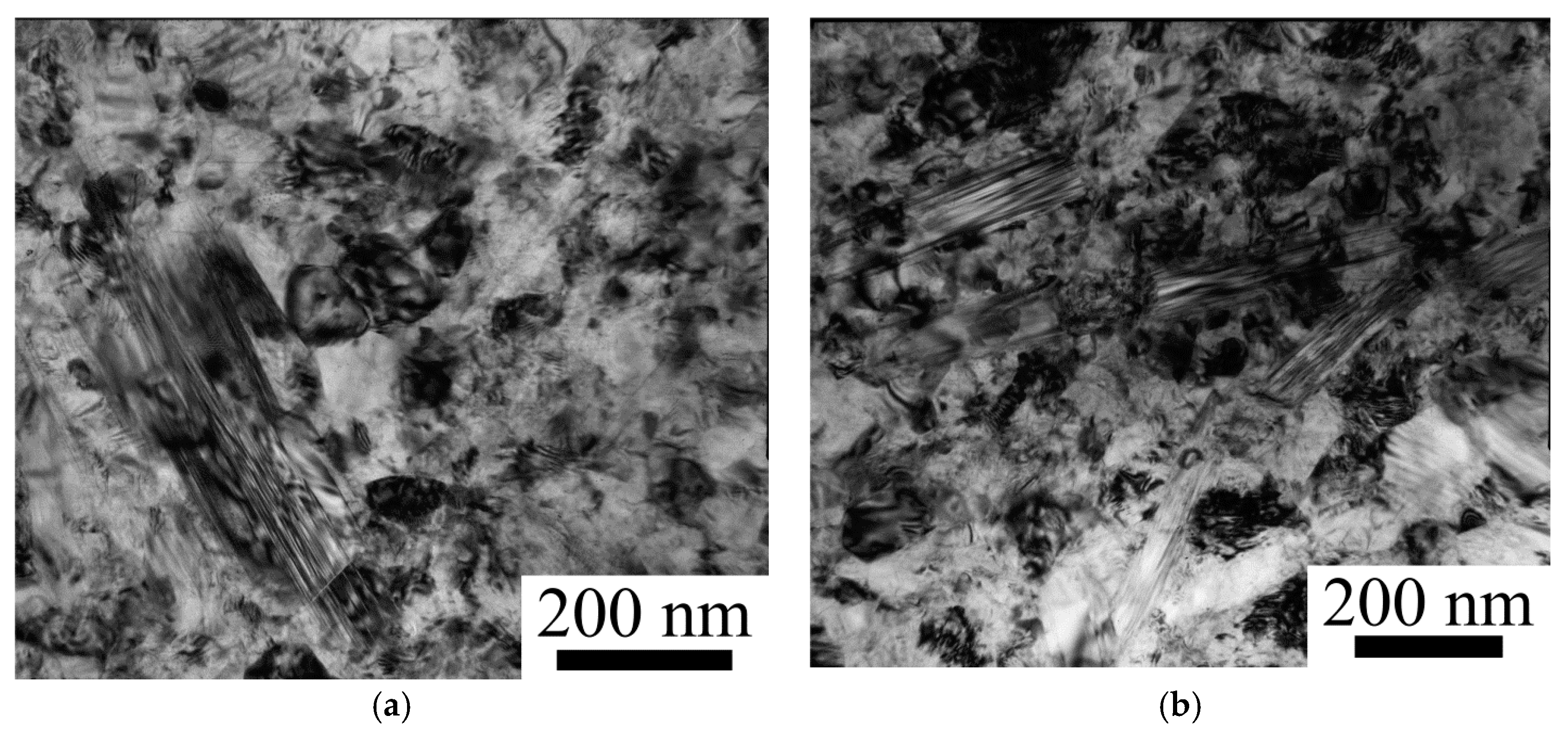
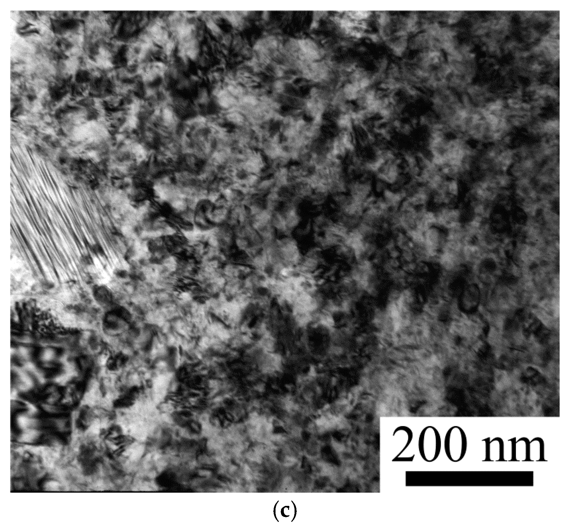
Processing by HPT produced a microstructure with (sub)grains of ~34 nm after five revolutions (γ ≈ 157). The microstructure evolution was associated with an intensive increase in dislocation density and substructure development, resulting in a gradual microstructure refinement of the Ti matrix and shortening/redistribution of TiB whiskers.
(2)
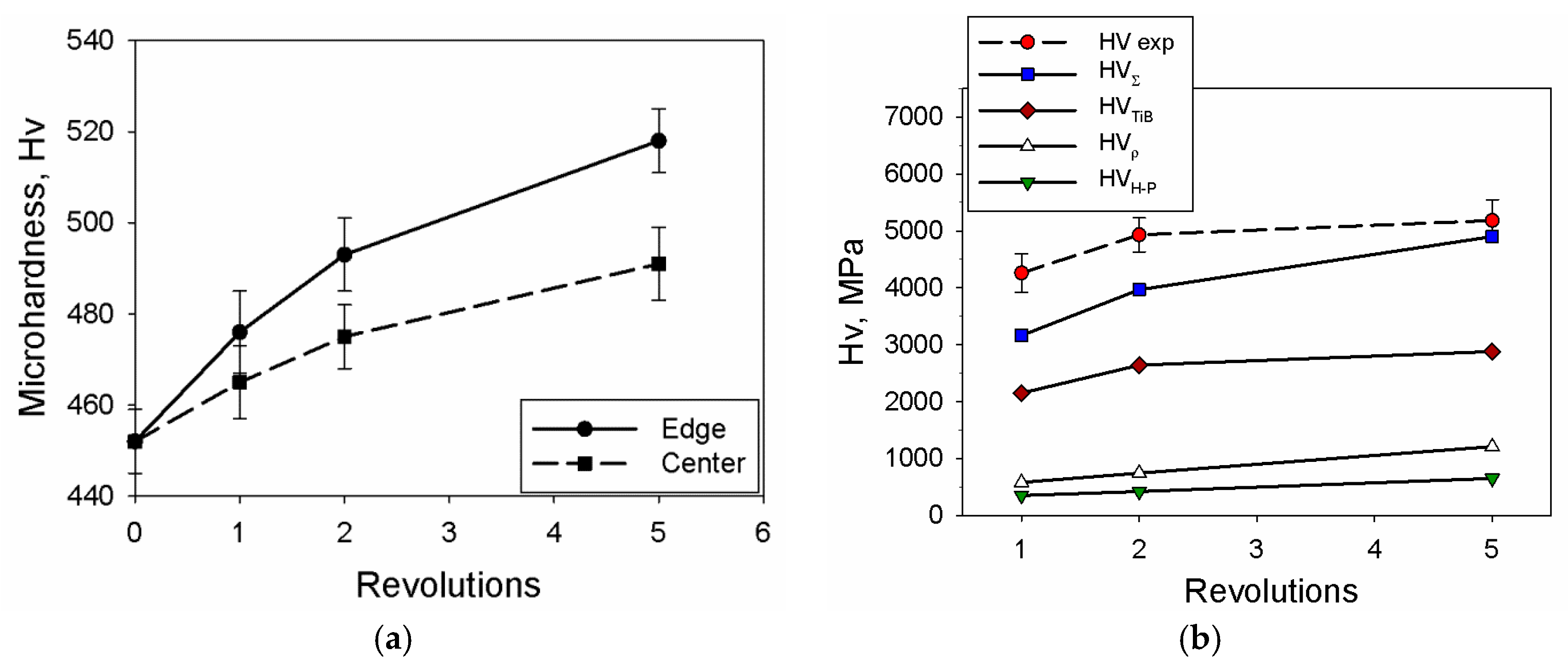
The microhardness increased with strain attaining the maximum value (~520 HV) at the edge of the disk after five revolutions. Analysis of contributions of different hardening mechanisms into the hardness of the Ti/TiB metal–matrix composite shows that an increase in hardness can mostly be ascribed to a contribution of precipitation hardening. The combined effect of substructure and Hall–Petch hardening give approximately two times lower contribution.

Acknowledgments

The authors gratefully acknowledge the financial support from the Russian Science Foundation (Grant Number 15-19-00165). The authors are grateful to the personnel of the Joint Research Centre, Belgorod State University for their assistance with the instrumental analysis.

Author Contributions

Sergey Zherebtsov, Yuliya Ivanisenko and Nikita Stepanov conceived and designed the experiments. Maxim Ozerov, Margarita Klimova and Yuliya Ivanisenko performed the experiments. Maxim Ozerov, Nikita Stepanov and Sergey Zherebtsov analyzed the data and wrote the paper.

Conflicts of Interest

The authors declare no conflict of interest.

References

  1. Leyens, C.; Peters, M. Titanium and Titanium Alloys. Fundamentals and Applications; Wiley-VCH: Weinheim, Germany, 2003; pp. 1–499. [Google Scholar]
  2. Saito, T.; Furuta, T.; Yamaguchi, T. Development of low cost titanium matrix composite. In Advances in Titanium Metal Matrix Composites, the Minerals, Metals and Materials Society; Froes, F.H., Storer, J., Eds.; TMS: Warrendale, PA, USA, 1995; pp. 33–44. [Google Scholar]
  3. Radhakrishna Bhat, B.V.; Subramanyam, J.; Bhanu Prasad, V.V. Preparation of Ti-TiB-TiC & Ti-TiB composites by in-situ reaction hot pressing. Mater. Sci. Eng. A 2002, 325, 126–130. [Google Scholar]
  4. Li, S.; Sun, B.; Imaia, H.; Kondoh, K. Powder metallurgy Ti-TiC metal matrix composites prepared by in situ reactive processing of Ti-VGCFs system. Carbon 2013, 61, 216–228. [Google Scholar] [CrossRef]
  5. Munir, K.S.; Zheng, Y.; Zhang, D.; Lin, J.; Li, Y.; Wen, C. Improving the strengthening efficiency of carbon nanotubes in titanium metal matrix composites. Mater. Sci. Eng. A 2017, 696, 10–25. [Google Scholar] [CrossRef]
  6. Godfrey, T.M.T.; Goodwin, P.S.; Ward-Close, C.M. Titanium particulate metal matrix composites—Reinforcement, production methods, and mechanical properties. Adv. Eng. Mater. 2000, 2, 85–91. [Google Scholar] [CrossRef]
  7. Lindroos, V.K.; Talvitie, M.J. Recent advances in metal matrix composites. J. Mater. Process. Technol. 1995, 53, 273–284. [Google Scholar] [CrossRef]
  8. Yamamoto, T.; Otsuki, A.; Ishihara, K.; Shingu, P.H. Synthesis of near net shape high density TiB/Ti composite. Mater. Sci. Eng. A 1997, 239–240, 647–651. [Google Scholar] [CrossRef]
  9. Kumari, S.; Prasad, N.E.; Chandran, K.S.R.; Malakondaiah, G. High-temperature deformation behavior of Ti-TiBw in-situ metal-matrix composites. JOM 2004, 5, 51–55. [Google Scholar] [CrossRef]
  10. Tsang, H.T.; Chao, C.G.; Ma, C.Y. Effects of volume fraction of reinforcement on tensile and creep properties of in-situ TiBTi MMC. Scr. Mater. 1997, 37, 1359–1365. [Google Scholar] [CrossRef]
  11. Morsi, K.; Patel, V.V. Processing and properties of titanium–titanium boride (TiBw) matrix composites—A review. J. Mater. Sci. 2007, 42, 2037–2047. [Google Scholar] [CrossRef]
  12. Ravi Chandran, K.S.; Panda, K.B.; Sahay, S.S. TiBw-reinforced Ti composites: Processing, properties, application, prospects, and research needs. JOM 2004, 56, 42–48. [Google Scholar] [CrossRef]
  13. Feng, H.; Zhou, Y.; Jia, D.; Meng, Q.; Rao, J. Growth mechanism of in situ TiB whiskers in spark plasma sintered TiB/Ti metal matrix composites. Cryst. Growth Des. 2006, 6, 1626–1630. [Google Scholar] [CrossRef]
  14. Da Silva, A.A.M.; Dos Santos, J.F.; Strohaecker, T.R. Microstructural and mechanical characterisation of a Ti6Al4V/TiC/10p composite processed by the BE-CHIP method. Comp. Sci. Technol. 2005, 65, 1749–1755. [Google Scholar] [CrossRef]
  15. Ozerov, M.; Stepanov, N.; Kolesnikov, A.; Sokolovsky, V.; Zherebtsov, S. Brittle-to-ductile transition in a Ti-TiB metal-matrix composite. Mater. Lett. 2017, 187, 28–31. [Google Scholar] [CrossRef]
  16. Gaisin, R.A.; Imayev, V.M.; Imayev, R.M. Effect of hot forging on microstructure and mechanical properties of near α titanium alloy/TiB composites produced by casting. J. Alloys Compd. 2017, 723, 385–394. [Google Scholar] [CrossRef]
  17. Imayev, V.; Gaisin, R.; Gaisina, E.; Imayev, R.; Fecht, H.-J.; Pyczak, F. Effect of hot forging on microstructure and tensile properties of Ti-TiB. Mater. Sci. Eng. A 2014, 609, 34–41. [Google Scholar] [CrossRef]
  18. Huang, L.; Cui, X.; Geng, L.; Fu, Y. Effects of rolling deformation on microstructure and mechanical properties of network structured TiBw/Ti composites. Trans. Nonferr. Met. Soc. China 2012, 22, 79–83. [Google Scholar] [CrossRef]
  19. Ozerov, M.; Klimova, M.; Kolesnikov, A.; Stepanov, N.; Zherebtsov, S. Deformation behavior and microstructure evolution of a Ti/TiB metal-matrix composite during high-temperature compression tests. Mater. Des. 2016, 112, 17–26. [Google Scholar] [CrossRef]
  20. Valiev, R.Z.; Islamgaliev, R.K.; Alexandrov, I.V. Bulk nanostructured materials from severe plastic deformation. Prog. Mater. Sci. 2000, 45, 103–189. [Google Scholar] [CrossRef]
  21. Valiev, R.Z.; Estrin, Y.; Horita, Z.; Langdon, T.G.; Zechetbauer, M.J.; Zhu, Y.T. Producing bulk ultrafine-grained materials by severe plastic deformation. JOM 2006, 58, 33–39. [Google Scholar] [CrossRef]
  22. Zhilyaev, A.P.; Langdon, T.G. Using high-pressure torsion for metal processing: Fundamentals and applications. Prog. Mater. Sci. 2008, 53, 893–979. [Google Scholar] [CrossRef]
  23. Stolyarov, V.V.; Zhu, Y.T.; Lowe, T.C.; Islamgaliev, R.K.; Valiev, R.Z. Processing nanocrystalline Ti and its nanocomposites from micrometer-sized Ti powder using high pressure torsion. Mater. Sci. Eng. A 2000, 282, 78–85. [Google Scholar] [CrossRef]
  24. Edalati, K.; Iwaoka, H.; Horita, Z.; Konno, M.; Sato, T. Unusual hardening in Ti/Al2O3 nanocomposites produced by high-pressure torsion followed by annealing. Mater. Sci. Eng. A 2011, 529, 435–441. [Google Scholar] [CrossRef]
  25. Bachmaier, A.; Pippan, R. Generation of metallic nanocomposites by severe plastic deformation. Int. Mater. Rev. 2013, 58, 41–62. [Google Scholar] [CrossRef]
  26. Islamgaliev, R.K.; Buchgraber, W.; Kolobov, Y.R.; Amirkhanov, N.M.; Sergueeva, A.V.; Ivanov, K.V.; Grabovetskaya, G.P. Deformation behavior of Cu-based nanocomposite processed by severe plastic deformation. Mater. Sci. Eng. A 2001, 319–321, 872–876. [Google Scholar] [CrossRef]
  27. Williamson, G.K.; Hall, W.H. X-ray line broadening from filed aluminium and wolfram. Acta Metall. 1953, 1, 22–31. [Google Scholar] [CrossRef]
  28. Ozerov, M.; Klimova, M.; Vyazmin, A.; Stepanov, N.; Zherebtsov, S. Orientation relationship in a Ti/TiB metal-matrix composite. Mater. Lett. 2017, 186, 168–170. [Google Scholar] [CrossRef]
  29. Islamgaliev, R.K.; Kazyhanov, V.U.; Shestakova, L.O.; Sharafutdinov, A.V.; Valiev, R.Z. Microstructure and mechanical properties of titanium (Grade 4) processed by high-pressure torsion. Mater. Sci. Eng. A 2008, 493, 190–194. [Google Scholar] [CrossRef]
  30. Edalati, K.; Matsubara, E.; Horita, Z. Processing pure Ti by high-pressure torsion in wide ranges of pressures and strain. Metall. Mater. Trans. A 2009, 40, 2079–2086. [Google Scholar] [CrossRef]
  31. Hughes, D.; Hansen, N. Microstructure and strength of nickel at large strains. Acta Mater. 2000, 48, 2985–3004. [Google Scholar] [CrossRef]
  32. Humphreys, F.; Hatherly, M. Recrystallization and Related Annealing Phenomena, 2nd ed.; Elsevier: Oxford, UK, 2004; pp. 1–605. [Google Scholar]
  33. Chen, B.; Shen, J.; Ye, X.; Jia, L.; Li, S.; Umeda, J.; Takahashi, M.; Kondoh, K. Length effect of carbon nanotubes on the strengthening mechanisms in metal matrix composites. Acta Mater. 2017, 140, 317–325. [Google Scholar] [CrossRef]
  34. Frost, H.J.; Ashby, M.F. Deformation-Mechanism Maps; Pergamon Press: Oxford, UK, 1982; pp. 1–166. [Google Scholar]
  35. Conrad, H. Effect of interstitial solutes on the strength and ductility of titanium. Prog. Mater. Sci. 1981, 26, 123–403. [Google Scholar] [CrossRef]
  36. Kelly, A.; Tyson, W.R. Tensile properties of fibre-reinforced metals: Copper/Tungsten and copper/molybdenum. J. Mech. Phys. Solids 1965, 13, 329–350. [Google Scholar] [CrossRef]
  37. Harrell, T.J.; Topping, T.D.; Wen, H.; Hu, T.; Schoenung, J.M.; Lavernia, E.J. Microstructure and strengthening mechanisms in an ultrafine grained Al-Mg-Sc alloy produced by powder metallurgy. Metall. Mater. Trans. A 2014, 45, 6329–6343. [Google Scholar] [CrossRef]
  38. Mishnev, R.; Shakhova, I.; Belyakov, A.; Kaibyshev, R. Deformation microstructures, strengthening mechanisms, and electrical conductivity in a Cu-Cr-Zr alloy. Mater. Sci. Eng. A 2015, 629, 29–40. [Google Scholar] [CrossRef]
  39. Lukyanova, E.A.; Martynenko, N.S.; Shakhova, I.; Belyakov, A.N.; Rokhlin, L.L.; Dobatkin, S.V.; Estrin, Y.Z. Strengthening of age-hardenable WE43 magnesium alloy processed by high pressure torsion. Mater. Lett. 2016, 170, 5–9. [Google Scholar] [CrossRef]
Figure 1. XRD (X-ray diffraction) patterns of the Ti/TiB MMC (metal–matrix composite) sintered at 1000 °C.
Metals 07 00507 g001
Figure 2. Microstructure of the Ti/TiB composite sintered at 1000 °C: (a) unetched; or (be) etched surface. Images (ce) correspond to areas #1–3, respectively, in (a,b).
Metals 07 00507 g002
Figure 3. TEM (Transmission Electron Microscope) images of: (a) the initial microstructure of the Ti/TiB composite; and (b) a cross-section of a TiB whisker.
Metals 07 00507 g003
Figure 4. SEM (Scanning Electron Microscope) images ((ac) unetched; and (d) etched) of the Ti/TiB MMC microstructure after HPT (high-pressure torsion): (a) one revolution at the edge of the specimen; (b) five revolutions in the center of the specim; (c,d) five revolutions at the edge of the specimen.
Metals 07 00507 g004
Figure 5. Apparent length of TiB whiskers in the Ti/TiB MMC after HPT.
Metals 07 00507 g005
Figure 6. TEM images of microstructure of the Ti/TiB MMC after HPT: (a) one revolution; (b) two revolutions; and (c) five revolutions.
Metals 07 00507 g006aMetals 07 00507 g006b
Figure 7. Microstructure parameters of the Ti/TiB MMC after HPT depending on the number of revolutions: (a) average (sub)grain size; (b) dislocation density.
Metals 07 00507 g007
Figure 8. Microhardness evolution of the Ti/TiB MMC during HPT: (a) Experimental data; and (b) contributions of various mechanism into hardness. Experimental data for the edge of the specimen was used in (b) as a reference.
Metals 07 00507 g008

