Article

Influence and Mechanism of Microstructure Refinement on the Hydrogen Embrittlement Resistance of 34MnB5

1
College of Materials Science & Engineering, Chongqing University, Chongqing 400039, China
2
China Automotive Engineering Research Institute Co., Ltd., Chongqing 401122, China
3
School of Metallurgy and Power Engineering, Chongqing University of Science and Technology, Chongqing 401331, China
4
School of Materials Science and Engineering, Shanghai Jiao Tong University, Shanghai 200240, China
5
CITIC-CBMM Microalloying Technical Center, CITIC Metal Co., Ltd., Beijing 100004, China
6
State Key Laboratory of Vanadium and Titanium Resources Comprehensive Utilization, Pangang Group Research Institute Co., Ltd., Panzhihua 617000, China
*
Authors to whom correspondence should be addressed.
Metals 2026, 16(8), 932; https://doi.org/10.3390/met16080932
Submission received: 14 April 2026 / Revised: 17 July 2026 / Accepted: 18 July 2026 / Published: 21 August 2026

Abstract

To investigate the effect of microalloying on hydrogen embrittlement resistance of hot-stamped steels with strength levels of 1.8 GPa and above, six composition schemes were designed based on conventional 34MnB5 steel, including three routes, namely Nb, V, and Nb–V. U-bend constant-strain bending tests and slow strain rate tensile (SSRT) tests were conducted on quenched specimens for each scheme. Results indicated that the Nb-containing compositions exhibited superior hydrogen embrittlement resistance. The mechanism by which microalloying refines the martensitic microstructure of 34MnB5 in the quenched state and enhances its resistance to hydrogen embrittlement was studied in detail. It was found that Nb exhibits stronger effects than V in refining and homogenizing the martensite structure. The fundamental reasons for Nb’s enhanced ability to pin austenite grain boundaries at high temperatures—leading to better microstructural refinement and homogenization—are its higher temperature range for second-phase precipitation, greater driving force for grain boundary diffusion, lower austenite grain boundary diffusion coefficient, and weaker tendency for high-temperature coarsening of precipitates. The microstructural refinement and homogenization induced by Nb addition are more pronounced than those achieved by combined additions of Nb and V. Furthermore, within the concentration range of 0–0.1%, the amount of Nb is positively correlated with the degree of microstructural refinement and homogenization. By reducing martensite lath size through microalloying, multiple microstructural modifications occur: decreased density of geometrically necessary dislocations (GNDs) in the matrix, significant increase in interface density—especially a higher proportion of high-angle grain boundaries—reduced number of Σ3 special harmful grain boundaries, weakened matrix texture intensity, fewer twin martensites, and smaller twin martensite sizes. These factors collectively contribute significantly to the improved hydrogen embrittlement resistance of Nb-containing steels.

1. Introduction

Hot stamping is one of the most advanced manufacturing technologies in automotive lightweighting, offering comprehensive advantages in safety, weight reduction, cost, and processability [1,2,3]. Driven by the global demand for extreme lightweighting and enhanced safety in vehicles, the development of higher-strength hot-stamped steels (≥1.8 GPa) beyond the conventional 1.5 GPa grade has become a key industry focus [4,5]. The microstructure of hot-stamped components is primarily martensitic, and as martensite strength increases, so does its susceptibility to hydrogen embrittlement [6,7]. Currently, ultra-high sensitivity to hydrogen embrittlement has become a critical barrier limiting the application of hot-stamped steels with strengths at or above 1.8 GPa. For hot-stamped steels, improving hydrogen embrittlement resistance primarily involves three aspects: original austenite grain size, precipitate phases, and retained austenite [8,9,10]. First, fine precipitates such as VC and NbC can act as strong “traps” for hydrogen atoms, capturing and immobilizing them to prevent diffusion toward potential crack initiation sites (e.g., grain boundaries or inclusions), thereby enhancing hydrogen embrittlement resistance [11,12]. However, the size, quantity, and distribution of precipitates are highly sensitive to the hot-forming process and difficult to precisely control. Coarse or unevenly distributed precipitates may instead become hydrogen enrichment sites or crack nucleation points. Retained austenite (RA) is also considered a hydrogen trap, and its transformation-induced plasticity (TRIP effect) can alleviate local stresses and suppress crack propagation. Nevertheless, in martensitic matrices obtained through conventional hot-forming processes, the content of retained austenite is extremely low (<5%), limiting its contribution to hydrogen embrittlement resistance. Moreover, its stability—whether it transforms into martensite under stress or hydrogen exposure—remains uncertain [13,14,15]. Grain refinement of the austenite phase represents the most prominent and effective approach to improving hydrogen embrittlement resistance in hot-stamped steels. By refining austenite grains, the diffusion coefficient of hydrogen in steel can be significantly reduced, while the density of hydrogen traps increases, leading to enhanced resistance. The geometrically exponential increase in interface density provides numerous uniformly distributed shallow traps for hydrogen, preventing localized hydrogen over-enrichment. A fine-grained microstructure implies shorter average hydrogen diffusion paths, enabling hydrogen atoms to be more evenly captured at numerous interfaces rather than diffusing long distances to a few weak spots (such as coarse original austenite grain boundaries). Furthermore, according to the Hall–Petch relationship, grain refinement not only increases strength but also improves material toughness, fundamentally enhancing the material’s ability to resist hydrogen-induced crack initiation and propagation [16,17,18,19,20]. Therefore, compared to precipitate phases and retained austenite, austenite grain refinement offers a more reliable and stable solution for strengthening hydrogen embrittlement resistance by physically and geometrically increasing hydrogen trap density and improving the material’s intrinsic toughness.
However, current research mostly remains at the superficial level of correlating “microstructure refinement” with “improved hydrogen embrittlement resistance.” There is still a lack of systematic studies on how refinement precisely modulates multi-scale substructural parameters of martensite and thereby systematically influences the state of hydrogen within martensite. Existing studies have shown that refining martensite triggers a cascade of changes in its substructural characteristics, all of which are closely related to martensitic hydrogen embrittlement behavior. First, fine-grained microstructures may generate higher or more uniform dislocation densities during phase transformation. Dislocations act as hydrogen traps, but their networks can also serve as fast diffusion pathways for hydrogen (the risk increases with higher strength). Therefore, altering the dislocation density in martensite through microstructure refinement can significantly change hydrogen diffusion behavior, thus affecting the susceptibility of the matrix to hydrogen embrittlement [21]. Second, how microstructure refinement quantitatively affects the proportions of various interfaces in martensite is another critical issue. Refinement increases the total interface area and may also alter the fraction of coincident site lattice (CSL) grain boundaries, particularly those with low Σ values (e.g., Σ3), which are known to influence the hydrogen embrittlement sensitivity of the matrix [22,23]. Third, texture is often an overlooked yet key factor. The refinement of original austenite grains alters the selection rules of martensite variants during quenching transformation, thereby influencing the texture characteristics of martensite, whose intensity and type in turn affect the material’s resistance to hydrogen embrittlement [24,25]. Finally, different types of martensite (lath-type vs. twin-type) exhibit varying effects on hydrogen embrittlement resistance, with twinned martensite being relatively more sensitive [26]. Thus, it is essential to investigate how microstructure refinement impacts these distinct martensite types.
Microalloying is currently the most widely used method to reduce the high hydrogen embrittlement sensitivity of hot-stamped steels, achieving microstructure modification and improved resistance to hydrogen embrittlement by adding elements such as Ti, Mo, Nb, and V. Considering performance, processability, and cost, Nb/V-based microalloying schemes are now commonly applied in the global steel industry, involving three technical routes: Nb-only, V-only, and Nb–V combined. Although previous studies have investigated the grain refinement effects of these three approaches on the microstructure of hot-stamped steels, there remains no definitive conclusion on which route is superior, and quantitative comparative validation under identical alloy systems is still lacking [27,28,29,30]. Particularly for hot-stamped steels with strength levels of 1.8 GPa or higher, their higher alloy content and more complex phase transformation behavior make the interactions among microalloying elements more subtle, resulting in a significant lack of fundamental experimental data. Moreover, studies have shown that adding only trace amounts (0.03–0.05%) of elements such as Nb and V can significantly reduce the hydrogen embrittlement sensitivity of 1.5 GPa hot-stamped steel. However, for hot-stamped steels with strengths above 1.8 GPa, the same microalloying strategy fails to meet requirements (making it difficult to pass automotive manufacturer certifications). Whether further increasing the content of Nb and V can resolve this issue remains a key concern in the global steel and automotive industries. Future research should focus on: (1) conducting more comprehensive and rigorous comparative experiments to clarify the grain refinement efficiency of different microalloying strategies in hot-stamped steels; and (2) revealing the multi-parameter synergistic evolution of martensite substructures induced by microstructure refinement, and its specific mechanisms in enhancing resistance to hydrogen embrittlement.
Based on the traditional 34MnB5 alloy system, this study designed three schemes incorporating Nb, V, and Nb–V, respectively. Quenched specimens of each scheme were subjected to U-bend constant-strain bending and slow strain rate tensile (SSRT) tests to evaluate their effects on hydrogen embrittlement susceptibility of 34MnB5 and to compare the advantages and disadvantages among the different schemes. Using a combination of optical microscopy (OM), scanning electron microscopy (SEM), transmission electron microscopy (TEM), and electron backscatter diffraction (EBSD), this work conducted qualitative and quantitative investigations into the differences in martensite refinement among the three schemes, as well as the evolution patterns and mechanisms of microstructural features at multiple scales—including geometrically necessary dislocations (GNDs), interfaces, texture, and twinned martensite—under refined martensite conditions. The findings provide valuable reference for addressing hydrogen embrittlement issues in hot-stamped steels with strength levels of 1.8 GPa and above within the industry.

2. Materials and Experimental Process

2.1. Materials

Six composition schemes were designed in this study (Table 1). Scheme 1# is a non-microalloyed scheme, schemes 2# and 3# are single Nb addition schemes, schemes 4# and 5# are single V addition schemes, and scheme 6# is a combined Nb–V addition scheme.
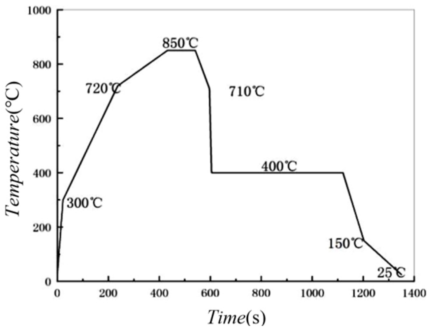
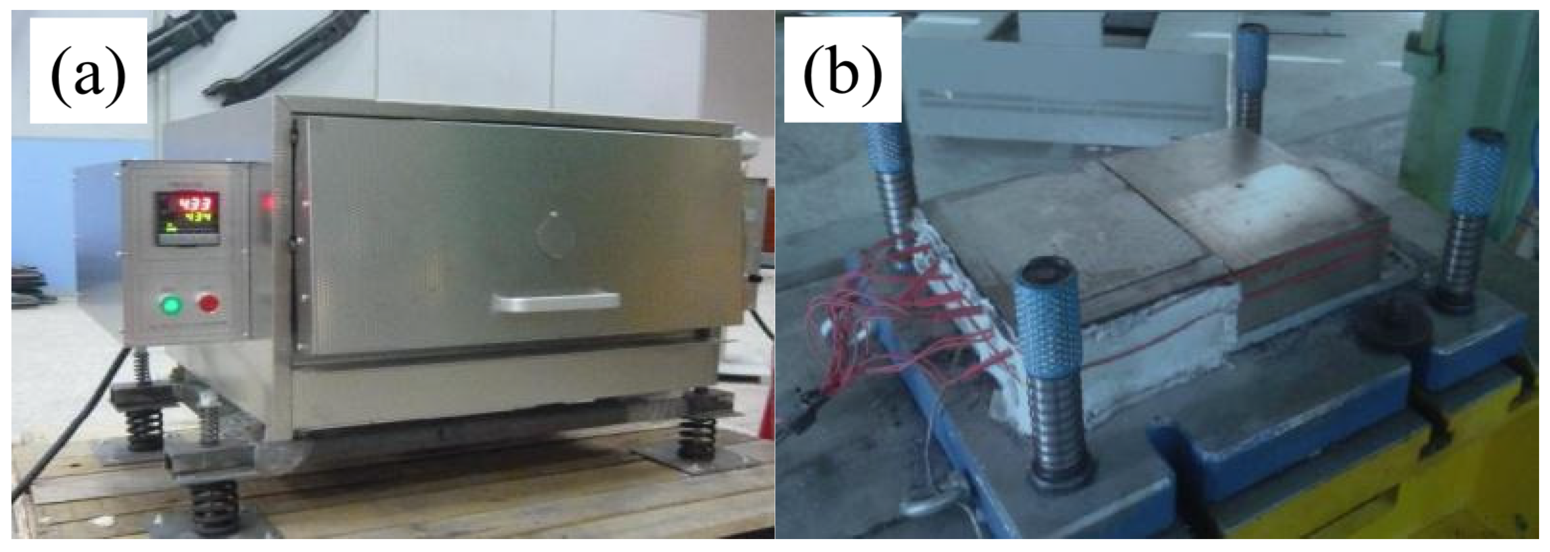
For each scheme, vacuum smelting is first carried out to obtain ingots (150 kg), which are then forged to facilitate subsequent processing and improve the quality of the ingot structure. The forging heating temperature is 1200 ± 20 °C, and the holding time is 3.5 h. The ingots are repeatedly hammered and then sawn into small blocks of 22 × 220 × 300 mm. The forged billets are then hot-rolled. The heating temperature before hot-rolling is 1250 ± 20 °C, and the holding time is 5.0 h. The starting rolling temperature is 1200 ± 20 °C, the final rolling temperature is 900 ± 20 °C, and the coiling temperature is 600 ± 20 °C. Through eight passes of rolling, hot-rolled sheets of 3 × 220 × 1100 mm in size are obtained. After hot-rolling, the sheets are subjected to surface shot blasting to remove the oxide scale, followed by cold-rolling. The final thickness of the cold-rolled sheet is 1.4 mm. The cold-rolled sheets are cut into long samples of 75 × 460 mm and annealed according to the process in Figure 1. Figure 2 shows the sheets used in the experiment. Furthermore, the sheets of different schemes are quenched. Figure 3 shows the heating furnace and flat plate mold used for quenching. The heating system is to first heat to 930 °C (±2 °C) and hold for 5 min, then take out the sheets and quench them in the flat plate mold. The surface of the quenched samples is shot blasted to remove the oxide scale, and then cut to the specified size for the experiment.

2.2. U-Shaped Constant-Strain Bending Test

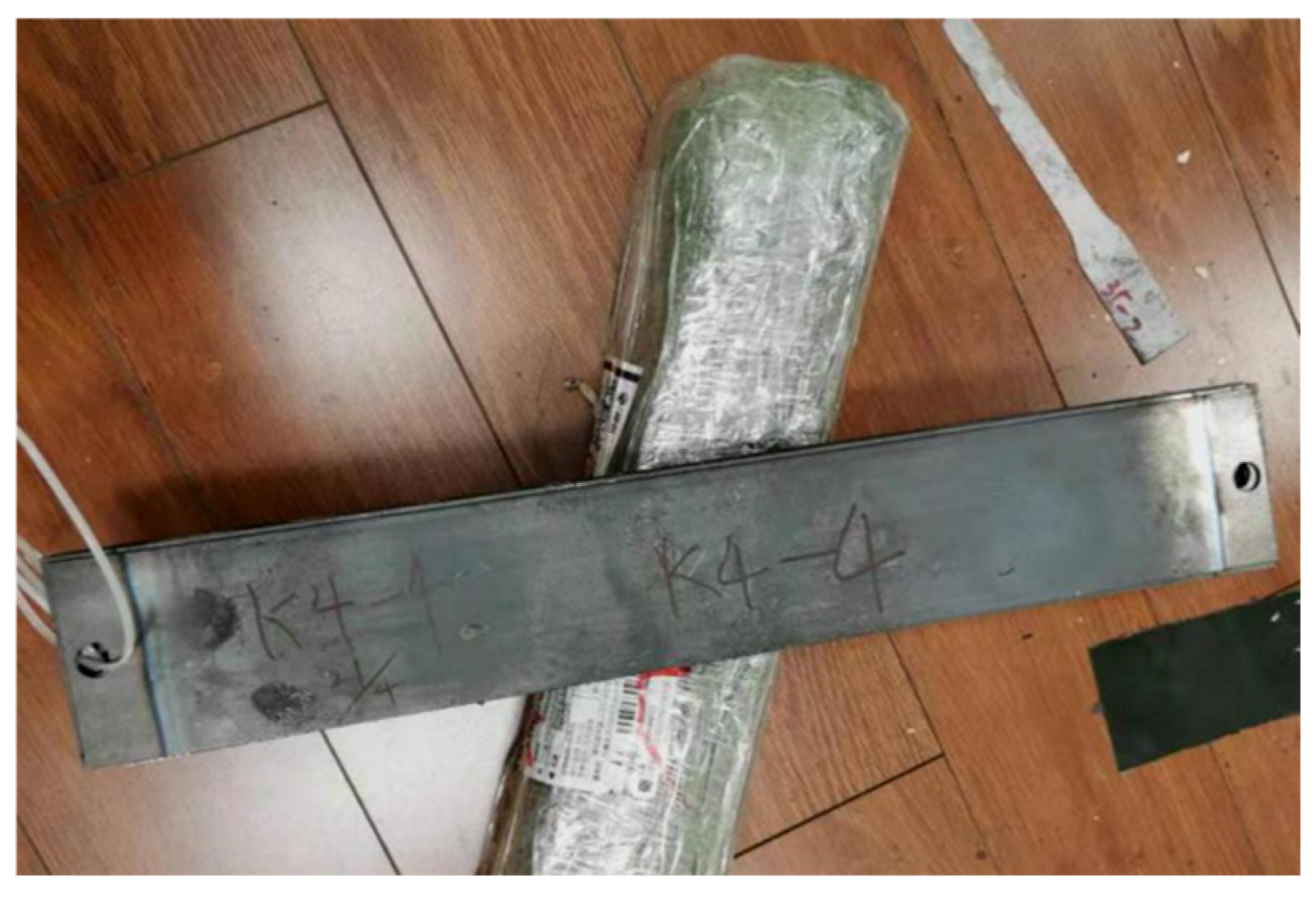
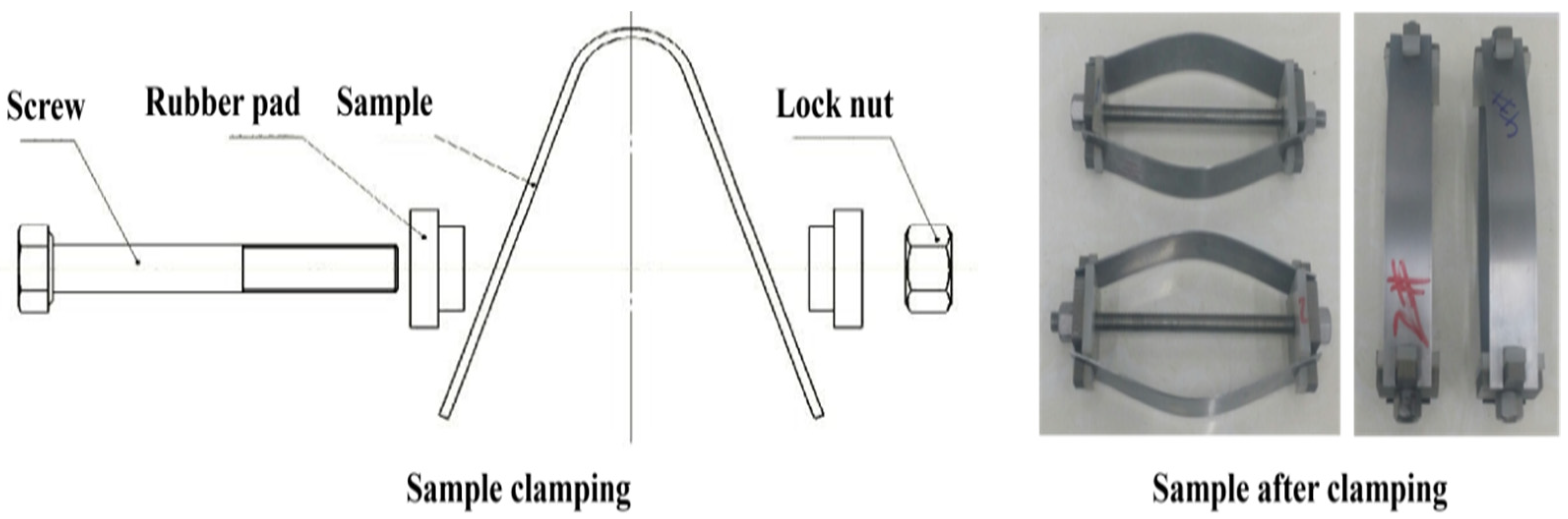
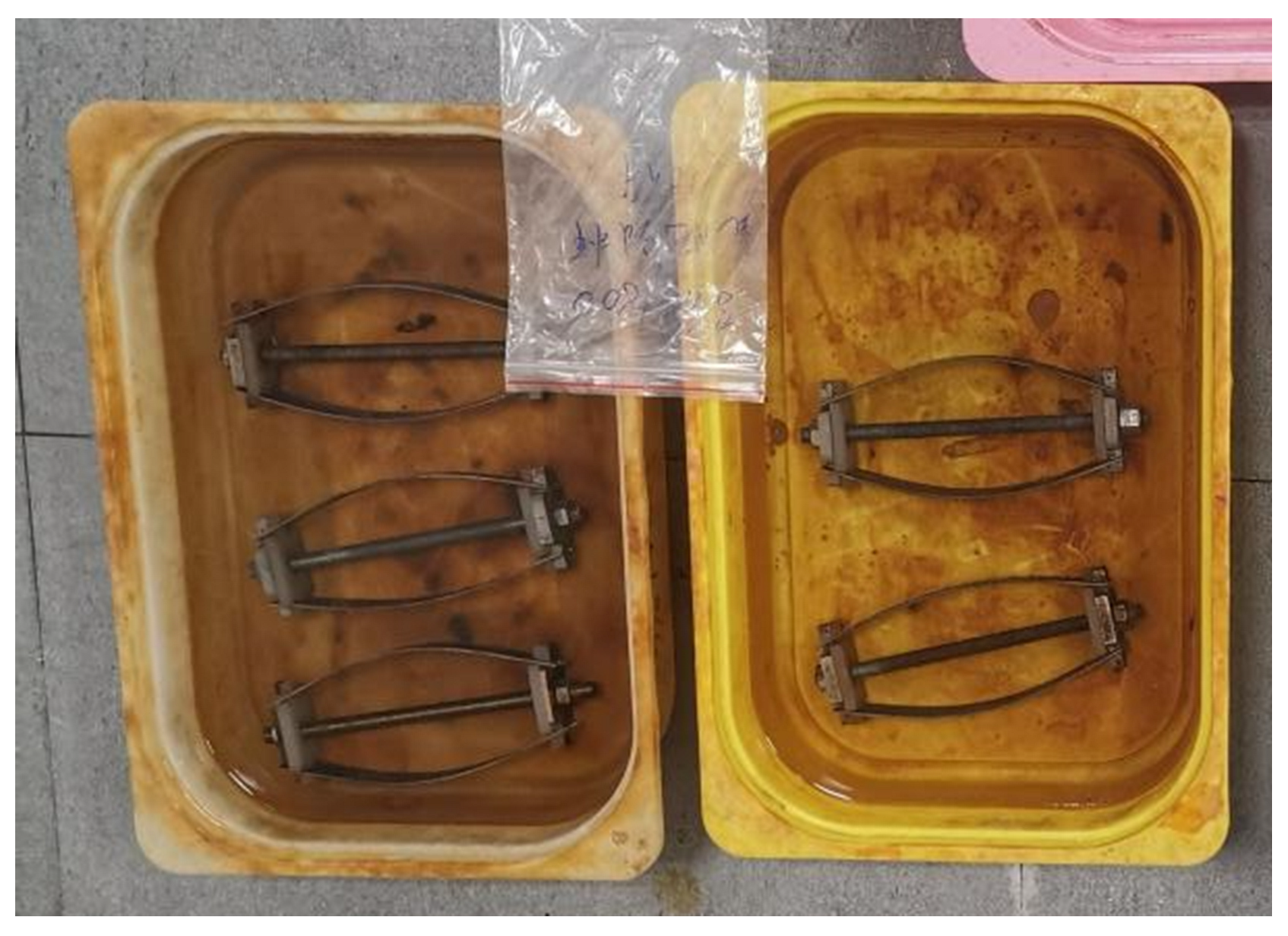
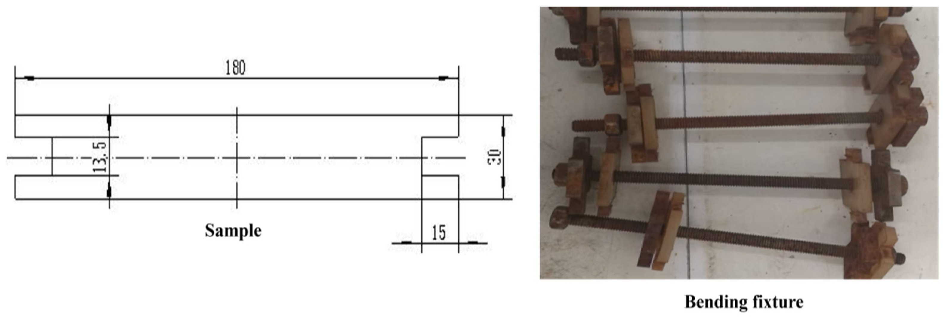
The U-shaped constant-strain bending test was carried out in accordance with the requirements of T/CSAE 155-2020 to evaluate the hydrogen embrittlement sensitivity of different schemes. Before the test, the quenched billets were machined into standard specimens (Figure 4). The specimens were placed in the middle of the bending fixture made of anti-corrosion material (Figure 4), and the sliding blocks on the fixture were pushed towards the middle by tightening the nuts at both ends of the fixture to bend the specimens. The target value of the bending span for all specimens was set at 145 mm (the same bending strain). The test was stopped when the bending span of the specimens met the requirements (Figure 5). There were 10 specimens for each scheme, which were divided into five groups, with two specimens symmetrically clamped on each fixture. After the bending loading of all specimens was completed, they were placed together with the fixtures in a 0.1 mol/L HCl solution (Figure 6) for soaking. The occurrence of cracking within 300 h was observed, and the number of cracked specimens was recorded [31].

2.3. Slow Strain Rate Tensile Test (SSRT)

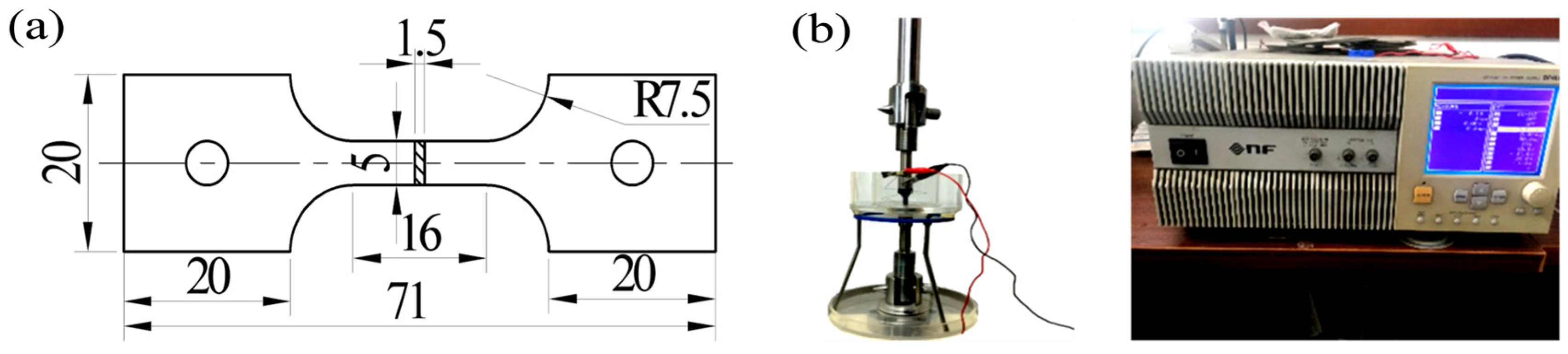
The slow strain rate tensile method was adopted to obtain the hydrogen embrittlement susceptibility index (EI) and evaluate the hydrogen embrittlement susceptibility of different schemes. For each scheme, slow strain rate tensile tests were conducted under hydrogen charging conditions. EI is equal to the loss rate of the post-fracture elongation A caused by hydrogen charging ((ANo charging − Acharging)/ANo charging), and the larger the value, the stronger the hydrogen embrittlement susceptibility. If the elongation of different materials is similar, the elongation under hydrogen charging conditions can be used as a substitute for EI. Figure 7 shows the sample size specifications and the appearance of the hydrogen charging equipment for the slow strain rate tensile test. The equipment model is Zwick (BTC-T1-FR020 TN.A50), the gauge length of the sample is 15 mm, the hydrogen charging tensile rate is 2 × 10⁻⁵ s−1, the electrolyte is NaCl (1 mol/L) + NH4SCH (1 g/L), the hydrogen charging current density is 5 mA/cm2, and the hydrogen charging time is 3 min.

2.4. Microstructure and Mechanical Property Characterization Tests

For the quenched specimens of different schemes, the following microstructure and property tests were carried out. The mechanical properties were evaluated by quasi-static tensile tests using a CMT5305 electronic universal testing machine (Suzhou Kechuang Measurement & Control Co., Ltd., Suzhou, China). The low-magnification microstructure characteristics of the specimens were evaluated by a LEICA DMI3000M metallographic (OM) microscope (Leica Microsystems, Wetzlar, Germany). The fracture morphology of the specimens after slow strain rate tensile treatment was observed by a JEOL7800F scanning electron microscope (JEOL, Ltd., Akishima, Tokyo). The microstructure crystal structure characteristics of the specimens were quantitatively evaluated by an OXFORD EBSD device (Oxford Instruments, Oxford, UK). The various precipitated phases in the specimens were observed by a JEOL 2100F transmission electron microscope (JEOL, Ltd., Akishima, Tokyo). The microstructure scale characteristics of the specimens at high temperatures under different schemes were detected by a VL2000DX-SVF17SP laser confocal microscope (Yonekura Manufacturing Co., Ltd., Yokohama, Japan). The sample preparation, process, and evaluation methods for the relevant tests were all carried out in the traditional way. In addition, to ensure comparability among different test results, all samples were taken from the central region of the steel plate. The specific sampling locations for each type of sample are also completely consistent.

3. Test Results

3.1. Tensile Mechanical Properties

Table 2 presents the quasi-static tensile results of the as-quenched specimens of each scheme in Table 1. It can be seen that the yield strength of all the specimens is in the range of 1200 to 1400 MPa, the tensile strength is in the range of 1800 to 2000 MPa, and the elongation after fracture is in the range of 7% to 8%. There are no significant differences overall, but there are slight variations. Scheme 1# has the lowest yield strength and elongation. Schemes 2# and 3# are single Nb addition schemes, which maintain high strength while also having relatively high elongation after fracture. Scheme 3# has the best strength and plasticity. Schemes 4# and 5# are single V addition schemes. Compared with schemes 2# and 3#, their yield, tensile strength, and elongation after fracture are slightly lower, but they are better than scheme 1#. Scheme 6# is a Nb–V compound scheme, which has slightly lower strength but the best elongation after fracture. The ranking of strength and plasticity for each scheme is as follows: scheme 3# > scheme 6# > scheme 2# > scheme 5# > scheme 4# > scheme 1#. The better the strength and plasticity, the better the toughness is often predicted. The resistance to hydrogen embrittlement is also a reflection of the toughness. From the results in Table 2, schemes 2#, 3#, and 6# may have the best resistance to hydrogen embrittlement, which will be further analyzed in the subsequent chapters.

3.2. U-Shaped Constant-Strain Bending Test

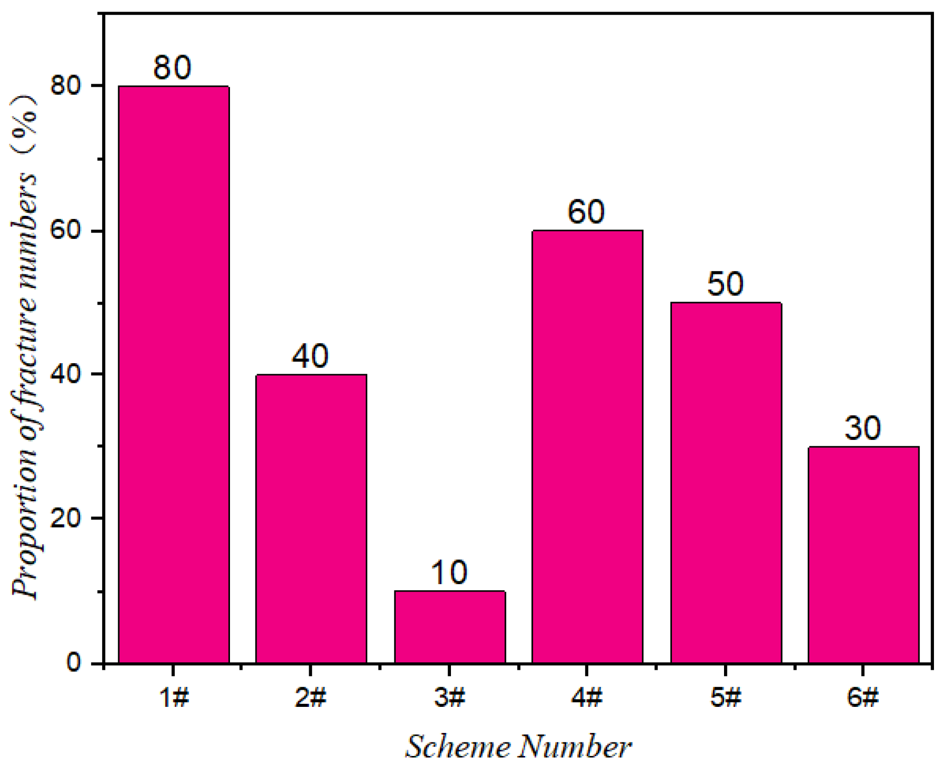
Table 3 and Figure 8 present the results of U-shaped constant-strain bending tests on quenched specimens of different schemes. It can be seen that under the same test conditions, scheme 1# has the most fractured specimens and the poorest resistance to hydrogen embrittlement. Scheme 2# has four fractured specimens at 300 h, while scheme 3# has only one, both showing significantly better resistance to hydrogen embrittlement than scheme 1#. The number of fractured specimens in schemes 4# and 5# is less than that in scheme 1#, but more than that in schemes 2# and 3#, indicating that their resistance to hydrogen embrittlement is stronger than that of scheme 1#, but weaker than that of schemes 2# and 3#. Scheme 6# also has only a few fractured specimens, demonstrating relatively excellent resistance to hydrogen embrittlement. The results show that the Nb-containing schemes have a significant advantage in hydrogen embrittlement resistance. The V-containing schemes have a lower hydrogen embrittlement resistance than the Nb-containing schemes, but they are still stronger than the schemes without microalloying treatment. Scheme 3# has the best resistance to hydrogen embrittlement. The order of resistance to hydrogen embrittlement among the six schemes is consistent with the order of their strength and plasticity.

3.3. Slow Strain Rate Tensile Test (SSRT)

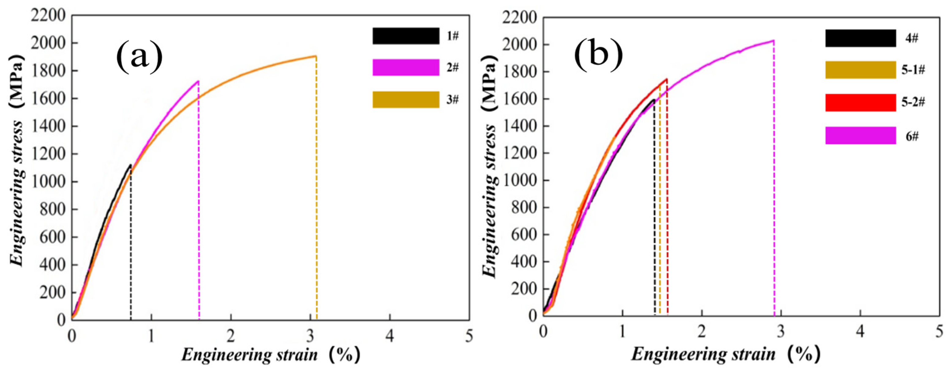
Given that the elongation after fracture of the six schemes’ samples under non-hydrogen conditions shows little overall difference, the elongation after fracture under hydrogen conditions can be simply used as the basis for evaluating their hydrogen embrittlement sensitivity. Figure 9 shows the test results. Scheme 1# has the lowest elongation after fracture under hydrogen conditions, indicating that its plasticity is most sensitive to hydrogen. Schemes 2# and 3# also show plasticity loss under hydrogen conditions, but the extent of the loss is significantly lower than that of scheme 1#, demonstrating better resistance to hydrogen embrittlement, with scheme 3# being the best. The elongation after fracture under hydrogen conditions of scheme 4# is higher than that of scheme 1# but lower than that of scheme 2#. The elongation after fracture under hydrogen conditions of scheme 5# is higher than that of scheme 4# but slightly lower than that of scheme 2#. Scheme 6# has the second-highest elongation after fracture under hydrogen conditions after scheme 3#. The above results are consistent with the patterns in Table 3.
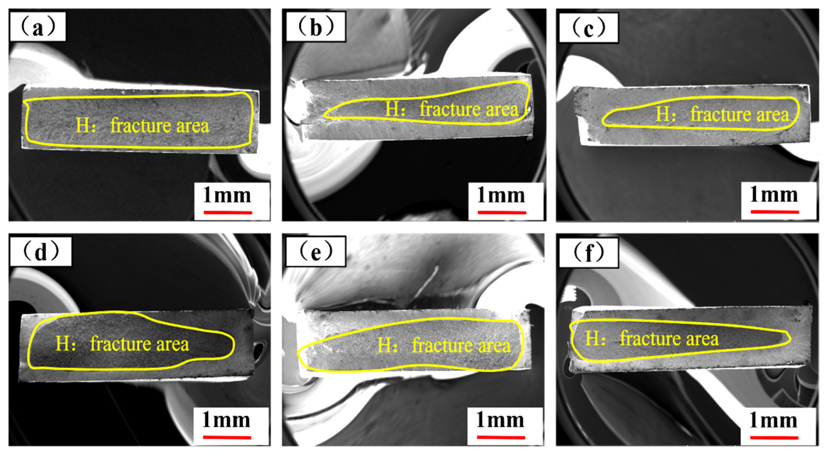
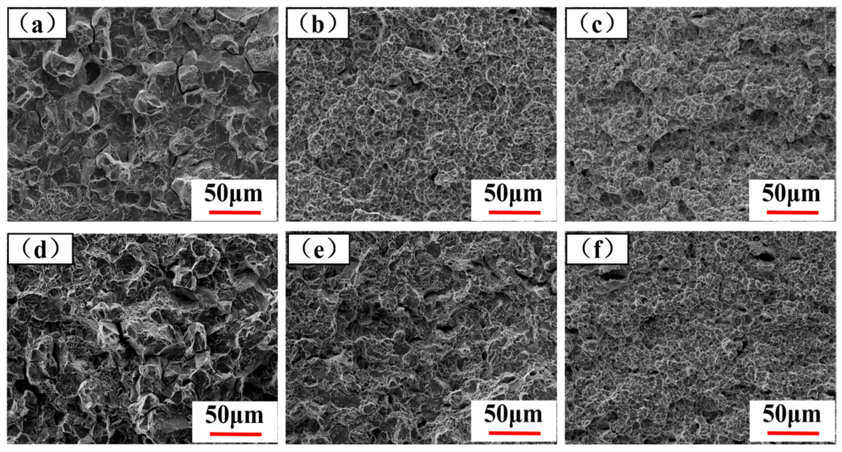
Figure 10 shows the macroscopic fracture morphology of the quenched specimens under different schemes at slow strain rate tensile tests. The hydrogen-induced fracture areas on each fracture surface are marked in each figure, and the size of these areas can reflect the hydrogen embrittlement sensitivity of the material. The larger the area, the stronger the hydrogen embrittlement sensitivity. The hydrogen-induced fracture area of scheme 1# is the largest, which is consistent with the result that its hydrogen embrittlement sensitivity is the strongest. The hydrogen-induced fracture areas of schemes 2#, 3#, and 6# are the smallest, indicating that the contribution of hydrogen to the fracture process of the specimens during the hydrogen-charged tensile test is the least. The hydrogen-induced fracture areas of schemes 4# and 5# are both smaller than that of scheme 1#, but larger than those of schemes 2#, 3#, and 6#. As shown in Figure 11, the hydrogen-induced fracture area of the specimen in scheme 1# shows obvious intergranular fracture characteristics, which is a typical fracture form (HEDE) often exhibited by steels with poor resistance to hydrogen embrittlement. The hydrogen-induced fracture areas of the specimens in schemes 2#, 3#, and 6# show significant dimple fracture characteristics (HELP). The specimen in scheme 4# shows strong intergranular and quasi-cleavage combined fracture characteristics (HEDE), while the hydrogen-induced fracture area of the specimen in scheme 5# shows strong quasi-cleavage and a small amount of dimple combined fracture characteristics (HEDE/HELP). Under the same conditions, the hydrogen embrittlement sensitivity of steels with HEDE fracture characteristics is stronger than that of steels with HELP fracture characteristics (HEDE fracture indicates more high-stress concentration areas in the matrix) [32]. The above results are also consistent with the regularity of the hydrogen embrittlement resistance of each scheme as reflected in the previous related tests.

4. Discussion

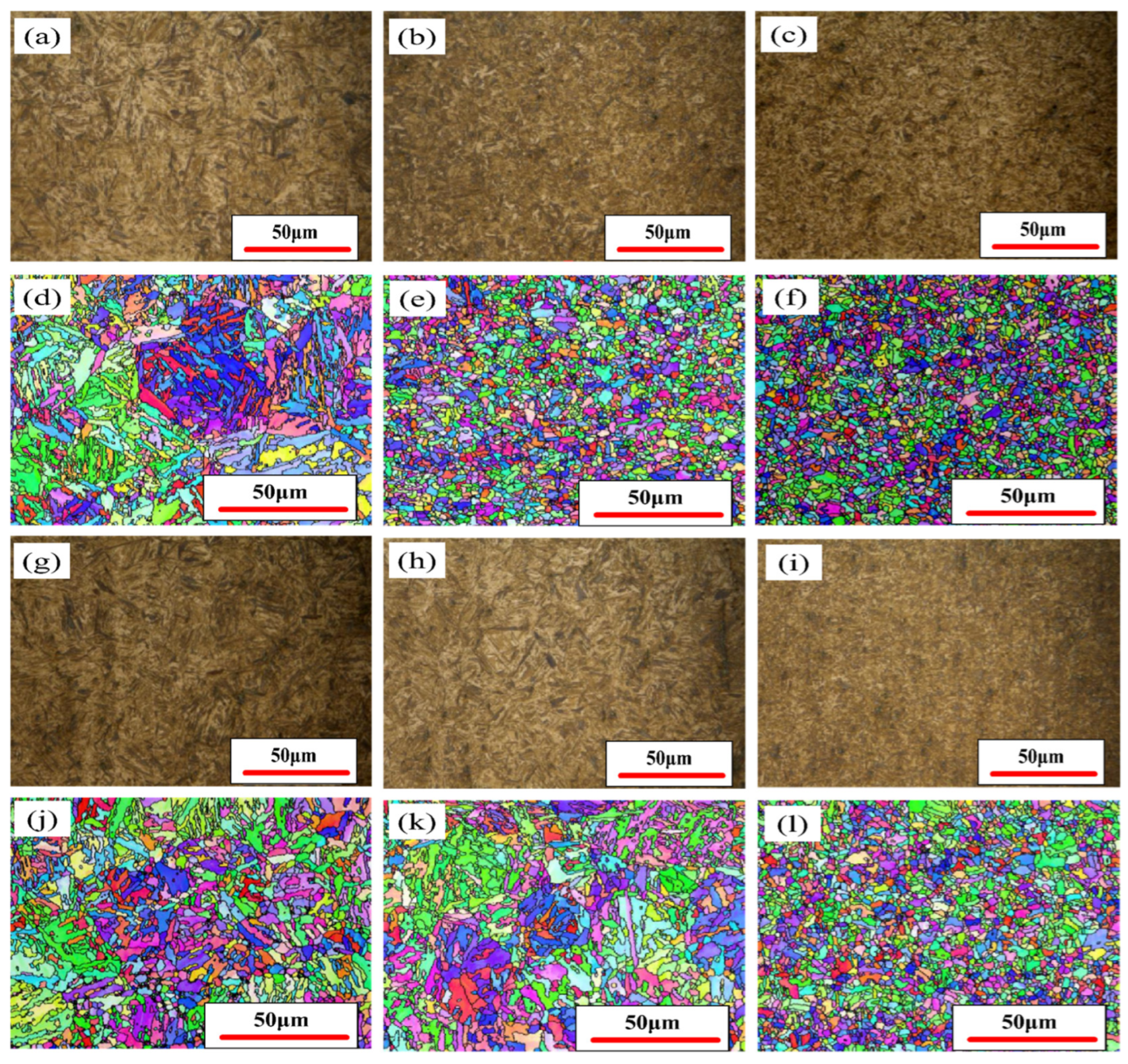
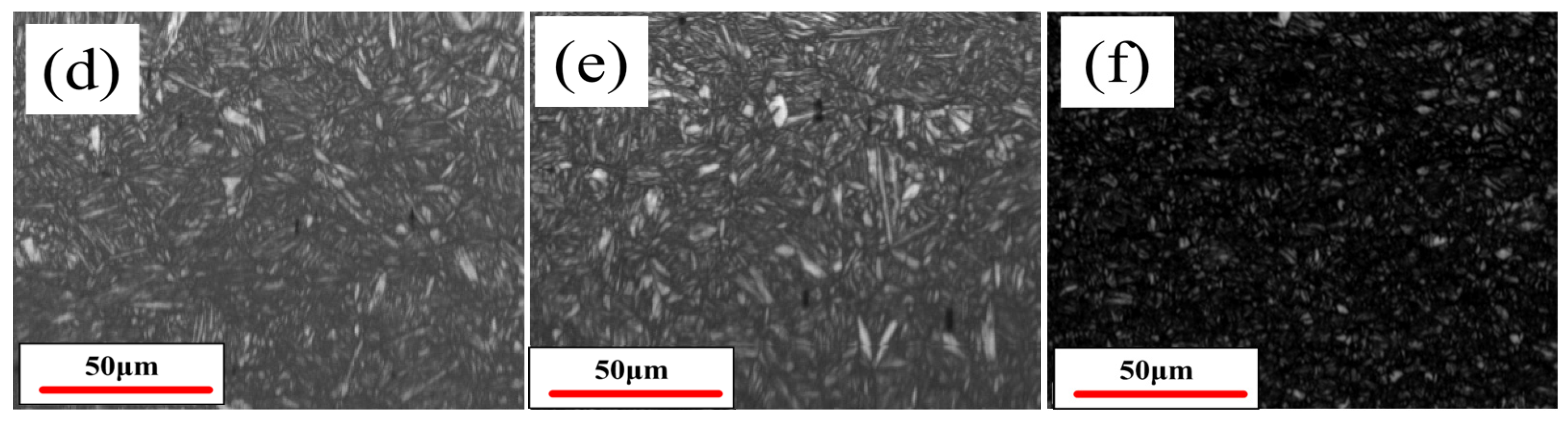
Refining the microstructure of steel through microalloying treatment can reduce its hydrogen embrittlement sensitivity. The threshold stress value for hydrogen-induced crack nucleation in steel is negatively correlated with the square root of the grain diameter D1/2 [33]. Figure 12 shows the quenched martensite (OM) and the lath size and morphology characteristics (EBSD) of samples from different schemes. It can be seen that the size of the quenched martensite laths of schemes 2#, 3#, and 6# is smaller. The size of the quenched martensite laths of scheme 1# is the largest. Schemes 4# and 5# are in the middle. The martensite lath sizes of the samples for schemes 1# to 6# are 7.22 μm, 3.21 μm, 3.11 μm, 5.62 μm, 5.95 μm, and 3.36 μm, respectively.
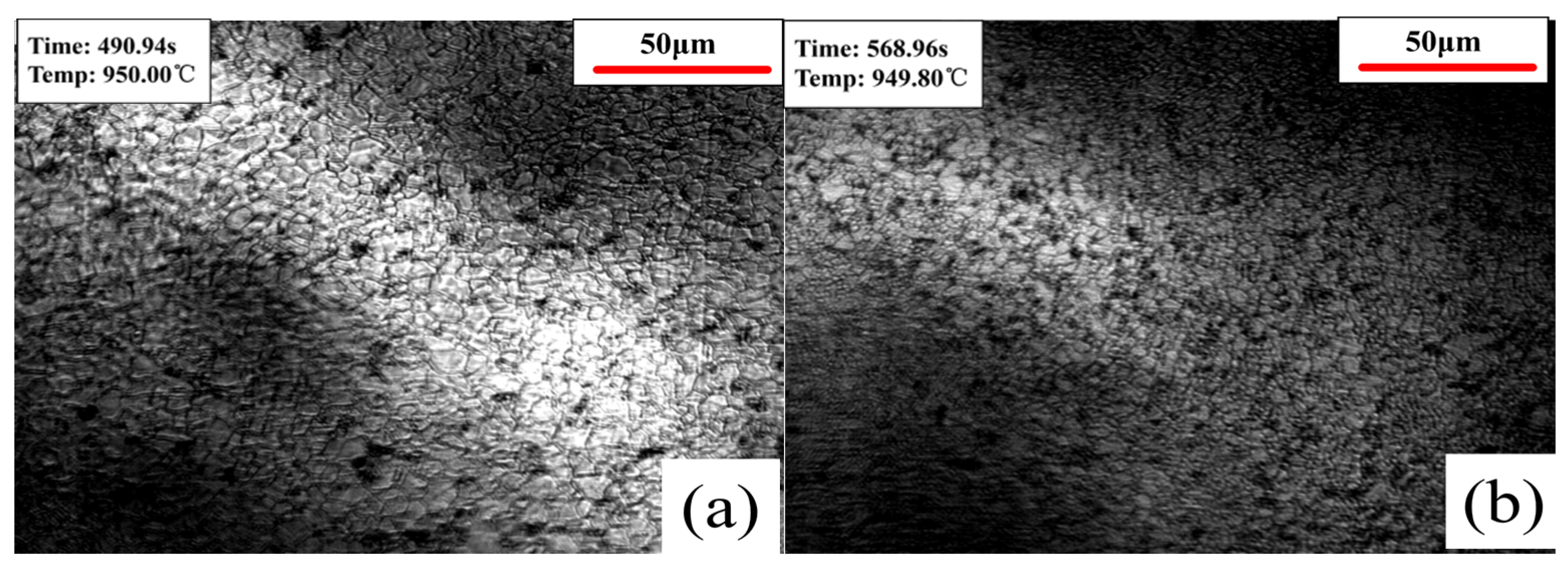
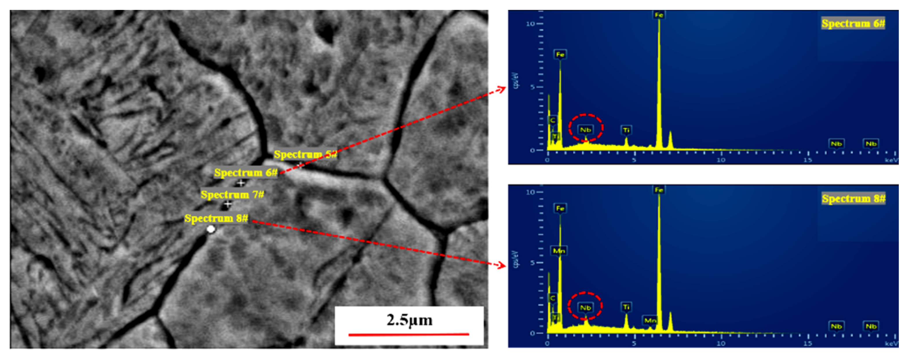
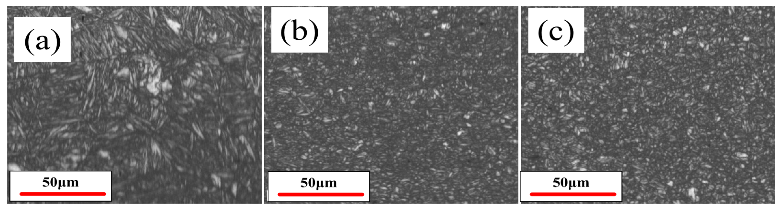
As can be seen from Figure 13, the microstructure of schemes 2#, 3#, and 6# is finer due to the addition of Nb. Schemes 4# and 5# added a trace amount of V, and compared with the non-microalloyed scheme 1#, only a slight microstructure refinement effect was produced. This also indicates that for hot-formed parts, it is difficult to significantly refine the microstructure by adding V. This is because at 930 °C, V is basically dissolved in austenite, and due to the high diffusion coefficient of V at high temperatures, it is difficult to accumulate at the grain boundaries, and its hindrance to the migration of austenite grain boundaries is very weak. Moreover, the driving force for the migration of austenite grain boundaries at high temperatures is significantly increased, resulting in the almost disappearance of the grain boundary pinning effect of V, and the refinement effect of austenite is poor [34]. Of course, considering the high-temperature factor, the fact that quenching cooling rate of the die quenching has not reached a very high level (≥100 °C/s), and the fact that other elements such as P and B in the steel also have a certain promoting effect on the grain boundary segregation of V [35], it also has a certain microstructure refinement effect, resulting in the microstructure of schemes 4# and 5# being slightly finer than that of scheme 1#. However, the amount of undissolved V segregated at the grain boundaries is still very small. According to the Zener mechanism, the hindrance effect of precipitation on the migration of grain boundaries is positively correlated with its volume fraction and negatively correlated with its size [36]. Under high-temperature conditions, the size of these undissolved V is prone to spheroidization due to the Ostwald ripening mechanism and gradually increases, resulting in the pinning effect of V on the austenite grain boundaries gradually decreasing over time, further reducing the refinement effect. Unlike V, Nb is a high-temperature precipitating element, and its solubility in austenite is about 1/10 to 1/100 of V, and it can precipitate at about 1200 °C [37]. Secondly, the radius difference between Nb and γ-Fe atoms is greater than that of V (Nb: 0.143 nm, γ-Fe: 0.126 nm, and V: 0.132 nm), which causes Nb to exert a stronger lattice distortion effect in the grains than V, and its segregation to the grain boundaries can release more strain energy [38]. In addition, because the coherency between Nb (C, N) and the austenite matrix is stronger than that of V, its segregation to the grain boundaries can effectively compensate for the atomic mismatch in the austenite grain boundary region and indirectly stabilize the low-energy grain boundary configuration through the “chemical pinning” effect. Therefore, Nb has a much stronger grain boundary diffusion driving force than V, and this has been verified by relevant literature [39,40]. Thirdly, the diffusion coefficient of Nb in austenite (~10−14 m2/s) is lower than that of V (~10−13 m2/s), and the low diffusion rate makes it more difficult for Nb solutes and Nb (C, N) in the austenite grain boundaries to diffuse away from the grain boundaries [41]. Finally, the melting point of Nb (C, N) (about 3600 °C) is higher than that of V (C, N) (about 2650 °C), and the high-temperature maturation tendency of Nb (C, N) is lower, and its grain boundary pinning effect is more persistent [42]. In summary, multiple factors lead to Nb mainly segregating in the form of Nb (C, N) at the austenite grain boundaries at 930 °C, which will have a significant pinning effect on the migration of austenite grain boundaries during the high-temperature heating process, thereby producing a significant refinement effect on austenite (Figure 13). Figure 14 shows Nb (C, N) distributed along the original austenite grain boundaries in the quenched specimen of scheme 2#.
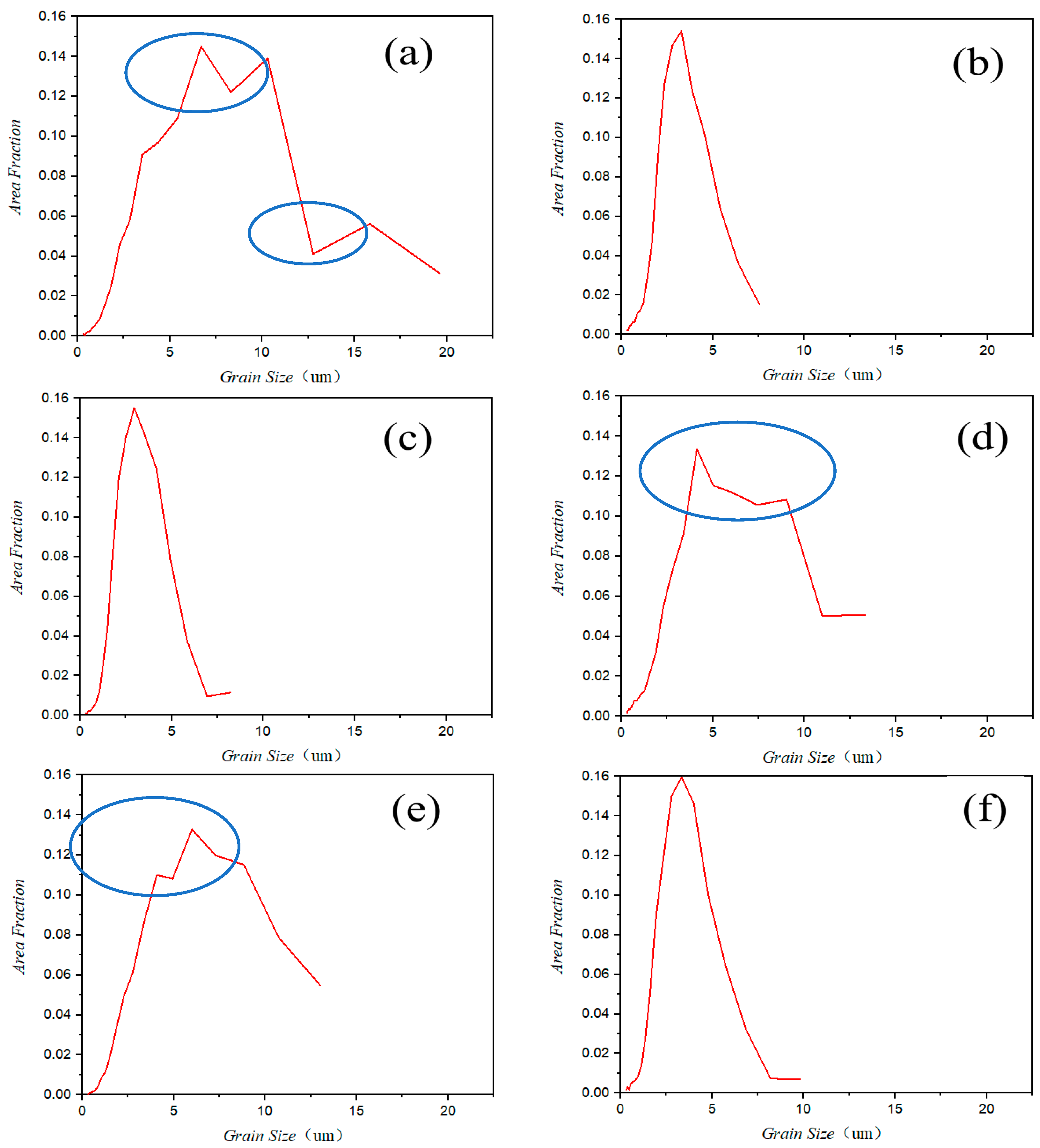
Figure 15 shows the distribution of the area fraction of martensite laths of different sizes in the six schemes’ samples (X-axis: martensite lath size). Firstly, it can be seen that for schemes 2#, 3#, and 6#, in addition to having smaller martensite lath sizes, the area fraction of martensite laths of different sizes changes uniformly from small to large. However, for the other schemes’ samples, the area fraction of martensite laths of different sizes changes with more or less abrupt variations. This indicates that the microstructure scale changes in schemes 2#, 3#, and 6# samples are nearly continuous, that is, they have very few mixed crystals, while the other schemes’ samples have abrupt changes in microstructure scale (area within the blue circle), that is, they have mixed crystals to varying degrees. The existence of mixed crystals will lead to stress concentration in the steel, which in turn promotes the accumulation of hydrogen in these areas, causing hydrogen embrittlement [43]. This is also the reason why the test results of hydrogen embrittlement resistance of schemes 2#, 3#, and 6# are all more excellent. The reason for the above differences is that the high-temperature austenite grain boundary pinning effect of Nb (C, N) is more stable than that of V (C, N). During the heat treatment holding process of V-containing steel, with the extension of time, some V (C, N) at the grain boundaries may gradually lose its grain boundary pinning effect due to spheroidization, causing local grain growth and resulting in mixed crystals. In addition, the austenite of Nb-containing steel is more stable, resulting in a lower Ms point, which can play multiple roles such as increasing the driving force for phase transformation, promoting simultaneous and slow phase transformation in all parts of the matrix, improving the uniformity of solute atom distribution in austenite, enhancing the coordination of phase transformation stress transmission in the matrix, and improving the non-diffusivity of the phase transformation process, further enhancing the uniformity of the microstructure [44].
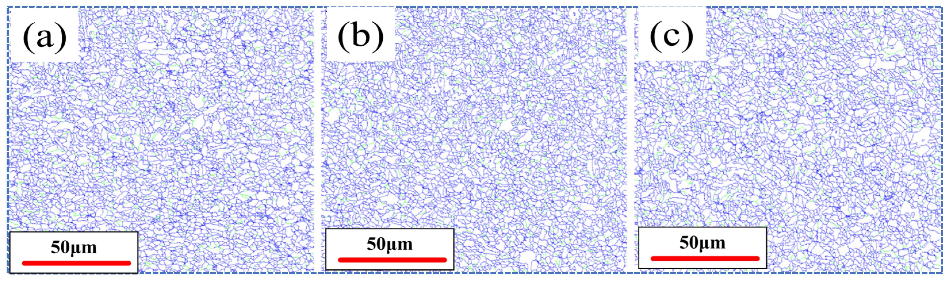
Thirdly, based on the EBSD test results, the average martensite lath bundle sizes of schemes 2#, 3#, and 6# were obtained as 3.20 μm, 3.10 μm, and 3.36 μm, respectively. Figure 16 shows the distribution diagram of the martensite lath bundle sizes of the three schemes. Compared with the other two schemes, the martensite lath bundles of scheme 3# are the finest and most uniformly distributed. The size and uniformity of the martensite lath bundles of scheme 2# are also slightly better than those of scheme 6#.
Firstly, for schemes 2# and 6#, the analysis indicates that V also has a strong carbon-fixing effect. It competes with Nb for carbon in steel, resulting in a lower volume fraction of Nb (C, N) compared to when Nb is added alone. Additionally, as previously mentioned, only a small amount of V plays a role in pinning the high-temperature austenite grain boundaries. This V exists in four forms at the grain boundaries. The first part remains as a solute, with a relatively weak pinning effect on the grain boundaries. The second part precipitates in conjunction with Nb, Ti, and other pre-precipitated phases to form composite phases, where the pre-precipitated phases still dominate. The third part is V (C, N), which is unstable and prone to spheroidization. The fourth part is V4C3, a small amount of which precipitates within the austenite at high temperature, a phenomenon which further reduces the carbon content in the austenite and, thus, lowers its stability, increases the Ms point, and, consequently, enhances the driving force for austenite grain boundary migration [45]. The combined effect of these multiple factors results in a slightly poorer microstructure refinement effect for scheme 6# compared to scheme 2#.
When comparing scheme 2# and scheme 3#, the microstructure of the sample in scheme 3# is finer and more uniform than that in scheme 2#, which is related to the difference in Nb content. According to the solubility product equation (Equation (1)), the maximum solubility of Nb can be calculated under the condition of carbon content being 0.34% and temperature being 1200 °C. Referring to [46], in Equation (1), A is taken as 2.96, B is taken as 7500, T is the absolute temperature of 1203 K, and [C] is taken as 0.34.
log 10 ( [ N b ] [ C ] ) = A B T
According to Equation (1), the maximum solid solubility of Nb at 1200 °C is approximately 0.0218%. Considering the reduction in the activity of carbon in steel and introducing an activity coefficient of 0.3 [47], the corrected Nb content can be calculated as 0.0218/0.3, which is about 0.08%. If this portion of Nb precipitates completely at 930 °C, it can exert the maximum grain refinement effect. However, based on Equation (1), it can be determined that there is still approximately 0.0102% of Nb dissolved in the matrix at 930 °C. Therefore, to fully release the grain refinement potential of Nb, the actual Nb content to be added is 0.08 + 0.0102 ≈ 0.1%, which is close to the Nb content in scheme 3#. The Nb content in scheme 2# is half that of scheme 3#, and the Nb potential release is insufficient, so the grain refinement effect must be weaker than that of scheme 3#. There is also an upper limit to the grain refinement effect of Nb on steel. Generally, when the Nb content exceeds 0.05%, further increasing the Nb content will significantly reduce the grain size reduction rate, and the Nb content–grain size curve will enter a plateau region [48]. Based on thermodynamic equilibrium theory, Zener pinning theory, and solute drag effect, the relationship between the minimum austenite grain size and the Nb content can be expressed as Equation (2). dmin is the minimum austenite grain size (mm), d0 is the theoretical limit grain size of austenite dynamic recrystallization (mm), [Nb] and [C] are the contents of Nb and carbon (wt%), K is a constant related to the pinning efficiency of the precipitated phase, m is the sensitivity index of carbon content to solubility (0.3–0.7), n is the refinement effect index of Nb content (0.5–1.2, usually taken as 1.0), α is the coupling coefficient of solute drag effect and carbon (0.1–1.0), and p is the influence index of carbon on solute drag (0.2–0.5) [49,50]. It can be seen that dmin gradually decreases with the increase of Nb content but eventually approaches d0. At least based on the results presented here, within the range of 0–0.1%, the effect of Nb on refining and homogenizing martensite in 34MnB5 continues to increase gradually with rising Nb content, providing a basis for the alloy design of Nb-containing hot-forming steels.
d min = d 0 + K [ C ] [ N b ] n + α [ C ] p m
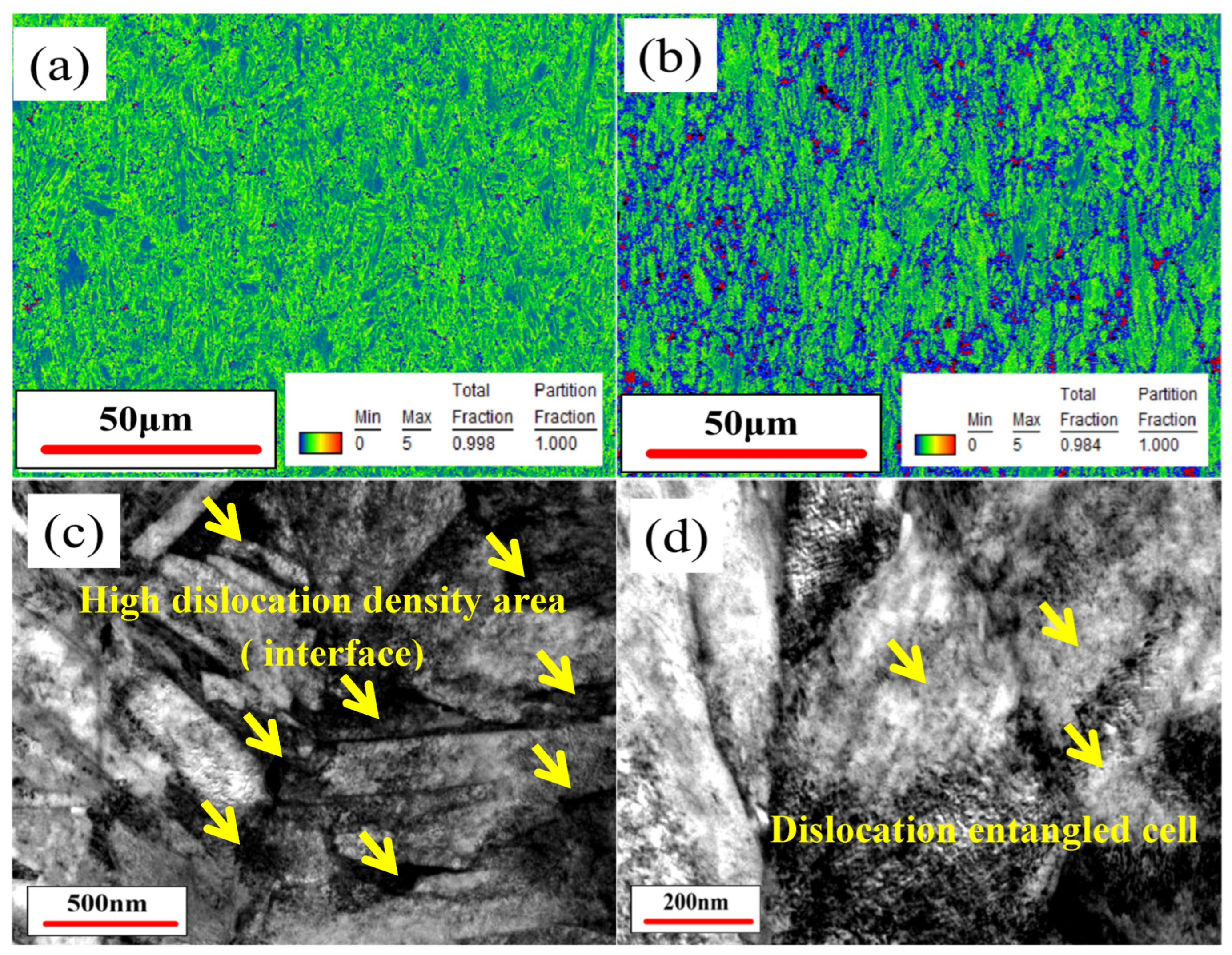
Dislocations act as reversible hydrogen traps (binding energy: 20–60 kJ/mol) but also serve as fast diffusion channels for hydrogen, especially when mobile dislocations transport hydrogen to grain boundaries, promoting hydrogen-induced intergranular fracture [51]. Additionally, ultra-high dislocation densities can form dislocation cells that act as “hydrogen absorption sinks” [52]. High dislocation density also reduces the plastic reserve of steel, increasing its hydrogen embrittlement sensitivity. In high-carbon martensite, the BCT lattice distortion during the austenite-to-martensite transformation generates high strain energy, resulting in a high dislocation density (up to 1015 m−2). Figure 17a,b show the comparison of KAM results obtained from EBSD tests for schemes 1# and 2#. KAM can be indirectly used as an indicator of the density of geometrically necessary dislocations (GNDs) in steel (generally indicated by the size of the blue and green areas in the KAM diagram). It can be seen that the KAM value of scheme 1# is higher than that of scheme 2# (the blue area has increased in size, while the green area has decreased), indicating a higher dislocation density. These high-dislocation-density areas can either act as “good helpers” for hydrogen diffusion or promote in-situ hydrogen-induced crack initiation, both of which will reduce the material’s resistance to hydrogen embrittlement.
It is generally believed that the dislocation density of steel increases after the refinement of its microstructure. However, the law shown in Figure 17 is exactly the opposite. This phenomenon has also been found in other studies [53,54,55]. The analysis suggests that, firstly, the strain coordination mode during phase transformation in the fine-grained system is different from that in the coarse-grained system. In coarse-grained steel, the macroscopic strain is generally coordinated by GNDs (high KAM value). When the martensite lath bundles are smaller, the strain generated by the martensitic transformation of the original austenite is dispersed into more lath bundles, resulting in a reduction in the lattice distortion that each lath needs to coordinate and a decrease in the driving force for dislocation multiplication [56]. Secondly, the smaller orientation difference between lath bundles will reduce the Schmid factor and thus reduce the accumulation of dislocations and the introduction of GNDs at the lath bundle interfaces to coordinate deformation. Previous research results have shown that when the original austenite grain size is reduced from tens of μm to several μm, the GND density in martensite can be reduced by 1–2 orders of magnitude [57]. Thirdly, the reduction in lath bundle size will increase the number of interfaces between bundles, thereby promoting dislocation annihilation [21]. The dislocation system in steel mainly includes GNDs, statistical stored dislocations (SSDs), etc. The addition of Nb can also promote the optimization of dislocation configuration, transforming the high-energy configuration of [high GNDs] + [dispersed SSDs] in the original coarse-grained structure into a low-energy configuration of [low GNDs] + [high-density dislocation walls/cells], reducing the long-range stress field (the main function of GNDs is to coordinate long-range strain). The above laws are usually reflected in EBSD tests as a shift of the dislocation density at the interface of fine-grained steel towards lower angles relative to the overall KAM peak (reduction of GNDs), but an increase in the dislocation density at the interface (Figure 17c,d). As shown in Figure 17d, in TEM tests, it is reflected as the observation of more dislocation cell structures in fine-grained steel [58,59,60]. The reduction of GNDs is beneficial to reducing the stress concentration in the steel matrix and delaying the initiation of hydrogen-induced cracks. Of course, the total dislocation density will still increase after the refinement of the martensite structure (the red area in Figure 17b), and the high strength is still maintained through the Taylor mechanism. Moreover, the reduction in GNDs indicates fewer hydrogen diffusion pathways in steel, which is beneficial for hydrogen embrittlement resistance; however, the increase in total dislocation density creates more hydrogen diffusion channels, which is detrimental to hydrogen embrittlement resistance [61,62]. From the results of this paper, Nb-containing steel shows better hydrogen embrittlement resistance, indicating that the role of GNDs is more significant.
As shown in Figure 18, the IQ maps of schemes 1# to 6# obtained through EBSD testing are presented. It can be observed that the diffraction patterns in the IQ maps of schemes 2#, 3#, and 6# are relatively clear, while the diffraction pattern in the IQ map of scheme 1# is the most blurred. The diffraction patterns in the IQ maps of schemes 4# and 5# are only slightly clearer than that of scheme 1#. A clearer IQ map indicates a lower dislocation density of GNDs in the steel (IQ maps are more sensitive to GNDs than SSDs). Due to the refined microstructure of the three Nb-containing steels, based on the aforementioned mechanisms, the density of GNDs is reduced, resulting in better quality of the diffraction patterns in their IQ maps. The V-containing steel, due to its poor microstructure refinement effect, has a higher density of GNDs in the matrix, leading to severe lattice distortion and thus a poorer quality of the diffraction pattern in its IQ map, only slightly better than that of scheme 1#. The results of the IQ maps are consistent with those of the KAM, further verifying the advantage of Nb in enhancing the resistance to hydrogen embrittlement by reducing the density of GNDs in martensite. The ranking of the six schemes based on the quality of the diffraction patterns in the IQ maps remains as scheme 3# > scheme 6# > scheme 2# > scheme 5# > scheme 4# > scheme 1#, which is consistent with the previously mentioned patterns of the hydrogen embrittlement performance test results.
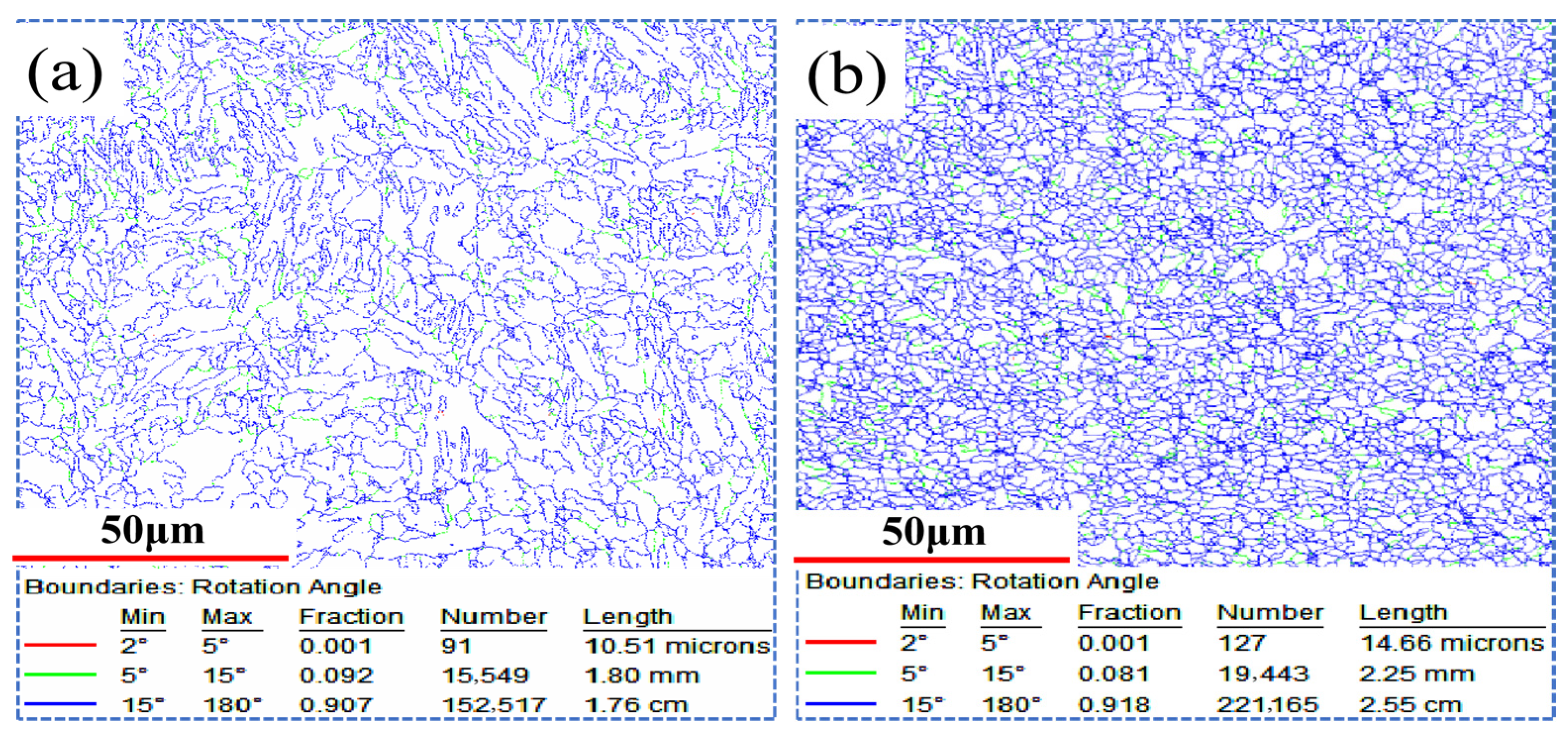
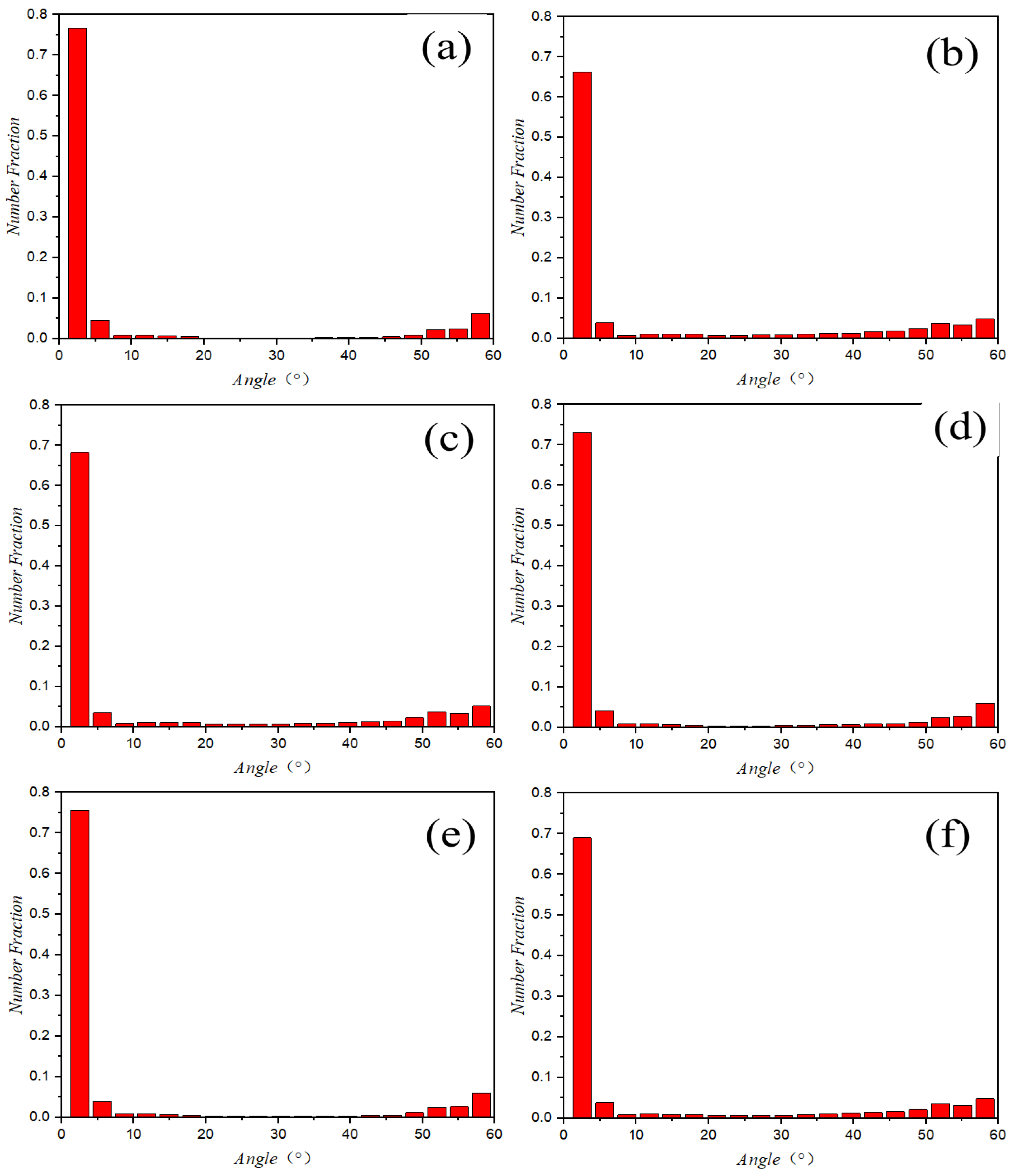
The variation in microstructure size will also affect the orientation distribution of the steel’s microstructure, thereby influencing its resistance to hydrogen embrittlement [63]. Figure 19 presents the EBSD test results of the grain orientation distribution for samples of scheme 1# and scheme 2#. As shown in Figure 19a,b, they represent the orientation distribution at the interfaces of samples of scheme 1# and scheme 2#, respectively. Among them, red indicates interfaces with orientations within the range of 1 to 5 degrees, green indicates interfaces with orientations within the range of 5 to 15 degrees, and blue indicates interfaces with orientations within the range of 15 to 180 degrees. The red and green interfaces are low-angle grain boundaries (LAGBs), while the blue ones are high-angle grain boundaries (HAGBs).
As can be seen from Figure 20, the number and length of interfaces at all orientation angles in scheme 2# are significantly higher than those in scheme 1#, indicating that Nb-induced grain refinement substantially increases the total interface density in the martensitic matrix. Small-angle interfaces (1–15°), composed of dislocation arrays, create less lattice distortion and require a higher energy barrier for hydrogen passage due to their lower interfacial energy (0.1–0.5 J/m2) [64]. In contrast, large-angle interfaces (>15°) exhibit highly disordered atomic arrangements with abundant vacancies and free volumes, offering numerous low-energy “pipe” diffusion paths for hydrogen, with higher interfacial energy (0.5–1.0 J/m2) more conducive to hydrogen enrichment [65]. In niobium-containing steels, the significant increase in the number of two types of interfaces effectively reduces the concentration of hydrogen atoms per unit interface area, thereby suppressing the weakening effect of hydrogen atom accumulation at interfaces and increasing the difficulty of hydrogen diffusion along these interfaces. This means that under microstructure refinement conditions, the negative impact of high-angle grain boundaries on the steel’s resistance to hydrogen embrittlement is greatly mitigated, while, instead, making them more effective hydrogen traps, thus helping improve the steel’s resistance to hydrogen embrittlement [66].
As shown in Figure 20, the statistical results of the proportion of different orientation angles in the microstructures of schemes 1# to 6# are presented. The proportion of small-angle interfaces in schemes 2#, 3#, and 6# (8.2%, 8.6%, 8.5%) is lower than that in schemes 1#, 4#, and 5# (9.3%, 9.0%, 10.0%). Studies have shown that approximately 15% to 30% of the contribution to the hydrogen embrittlement resistance of medium- and high-carbon steels comes from small-angle interfaces, and approximately 70% to 85% comes from large-angle interfaces [67,68]. The proportion of large-angle interfaces in schemes 2#, 3#, and 6# is higher, and the number of both large- and small-angle interfaces has increased. The advantages of each type of interface have been more fully exerted, which is also one of the important reasons why the hydrogen embrittlement resistance of schemes 2#, 3#, and 6# is superior.
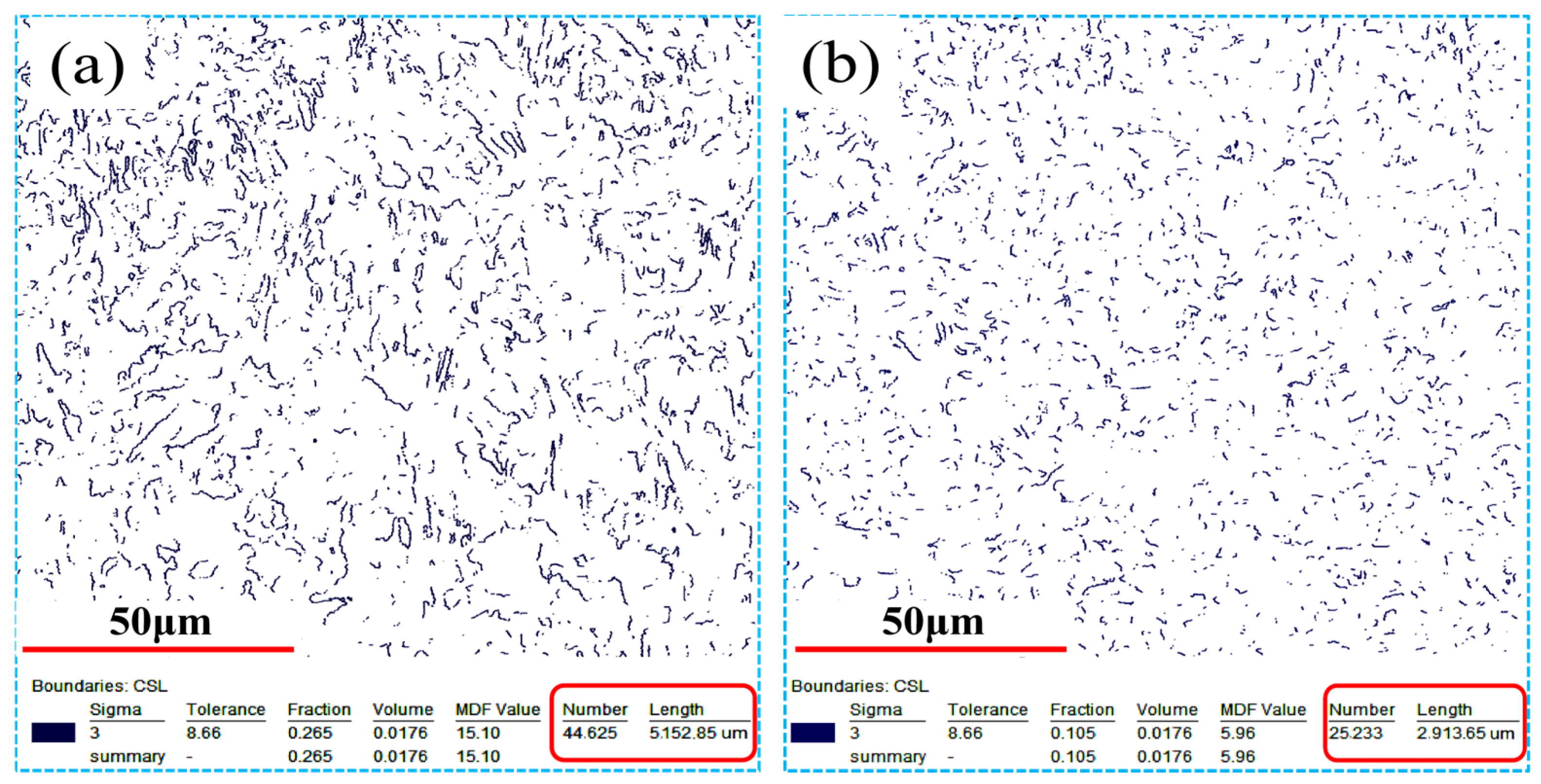
The variation in grain size can also lead to changes in the number of certain special grain boundaries in steel, thereby affecting the steel’s resistance to hydrogen embrittlement. As shown in Figure 21, the number of Σ3 grain boundaries in schemes 1# and 2# based on EBSD tests is presented. The number (25,233) and length (2.91 mm) of Σ3 grain boundaries in scheme 2# are both significantly lower than those in scheme 1# (number: 44,625, length: 5.15 mm). The Σ3 grain boundary (60° <111>) is a typical coherent twin boundary known to be detrimental to the hydrogen embrittlement resistance of martensite. The negative effects of Σ3 boundaries are fourfold. First, they are prone to hydrogen enrichment, with previous studies reporting significantly higher hydrogen concentrations at Σ3 boundaries than in other areas. Second, the high phase transformation stress during quenching of hot-formed steel can cause strong interaction between Σ3 boundaries and surrounding incoherent grain boundaries, leading to stress concentration that promotes hydrogen-induced crack nucleation. Third, the high dislocation density in martensite can easily disrupt the coherence of Σ3 boundaries; once disrupted, the formation of semi-coherent or incoherent interfaces further enhances hydrogen enrichment along these boundaries. Fourth, Σ3 boundaries are frequently included in hydrogen-induced crack propagation paths in martensite, especially under dynamic loading conditions [69,70,71,72].
In martensite, Σ3 boundaries originate from annealing twins in the original austenite and may be inherited during the austenite-to-martensite transformation, which follows the K–S (Kurdjumov–Sachs) or N–W (Nishiyama–Wassermann) orientation relationship [73]. When the original austenite grain size is large, Σ3 twin boundaries are more likely to be preserved as Σ3 grain boundaries in the martensite after phase transformation. By refining austenite grains through Nb addition, the nucleation energy barrier for twins is increased (twins require a critical grain size and are more prevalent in coarse grains), and the strain during martensite transformation is more uniformly distributed in fine-grained structures [74]. These effects promote more random variant selection and reduce the probability of inheriting Σ3 twin boundaries [75]. The EBSD results presented in Figure 21 confirm that Nb-induced grain refinement effectively reduces the population of these detrimental boundaries, which in turn contributes to the superior hydrogen embrittlement resistance of Nb-containing steels.
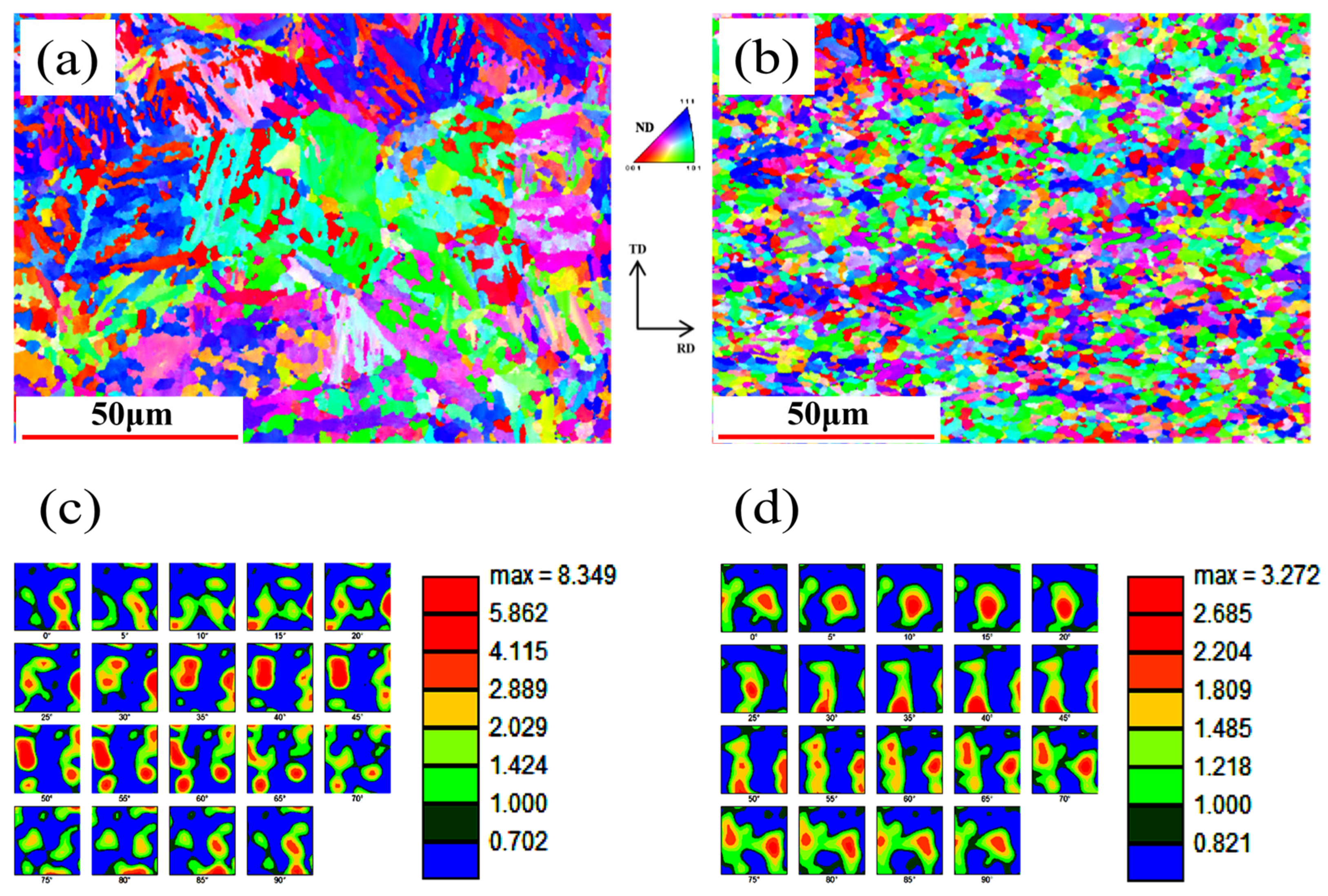
In addition, the texture changes caused by the variation in grain size of different scheme samples were also studied. Figure 22 shows the relevant texture information of schemes 1# and 2# based on EBSD testing. The texture strength can be evaluated using the random distribution multiplier (MRD). When MRD = 1, it indicates that no texture exists. The larger the MRD value, the higher the texture intensity, that is, the more significant the texture characteristics.
As shown in Figure 22a,b, the distribution of martensite lath bundles in scheme 2# along the [001], [101], and [111] orientations is highly dispersed, whereas in scheme 1# these bundles are strongly aggregated, with many regions showing net-like and clustered formations, indicating a stronger orientation concentration trend. Figure 22c,d show that the MRD value of scheme 1# is 8.349, significantly higher than that of scheme 2# (3.272), confirming that Nb addition greatly reduces the matrix texture intensity. Research indicates that in the BCC structure of steel, the atomic spacing along the [001] and [101] orientations is larger, facilitating hydrogen diffusion and promoting local stress concentration and hydrogen-induced crack nucleation under loading, whereas the [111] orientation has the densest atomic arrangement and the most tortuous hydrogen diffusion path, resulting in a lower hydrogen diffusion coefficient [76,77]. Therefore, the {001} <110> and {112} <110> textures are detrimental to hydrogen embrittlement resistance, while the {111} <ND> texture is beneficial.
The reduction in texture intensity arises from three mechanisms related to austenite grain refinement. First, fine-grained austenite transfers quenching strain energy more uniformly to all parts, reducing overall stress concentration and allowing martensite to largely inherit the texture orientation relationship of austenite in a more randomized manner [78]. Second, when austenite grains are very fine, martensite variants are more likely to grow across austenite grain boundaries, reducing the interference of grain boundaries on the randomization of variant orientations. Third, the more random orientation distribution in fine-grained austenite leads to more diverse martensite variant selection during quenching, and textures formed by different variants cancel each other out [79,80,81]. Studies have shown that for every 1 μm reduction in austenite size, the number of martensite variants increases by approximately 15%, and reducing austenite size from 50 μm to 5 μm decreases texture intensity by about 30% [21,82]. Low texture intensity means that the grain orientations are more random, and the interface distribution in the matrix is more dispersed, which can more effectively hinder hydrogen enrichment and diffusion, and delay the initiation and propagation of hydrogen-induced cracks, thereby improving the hydrogen embrittlement resistance [83].
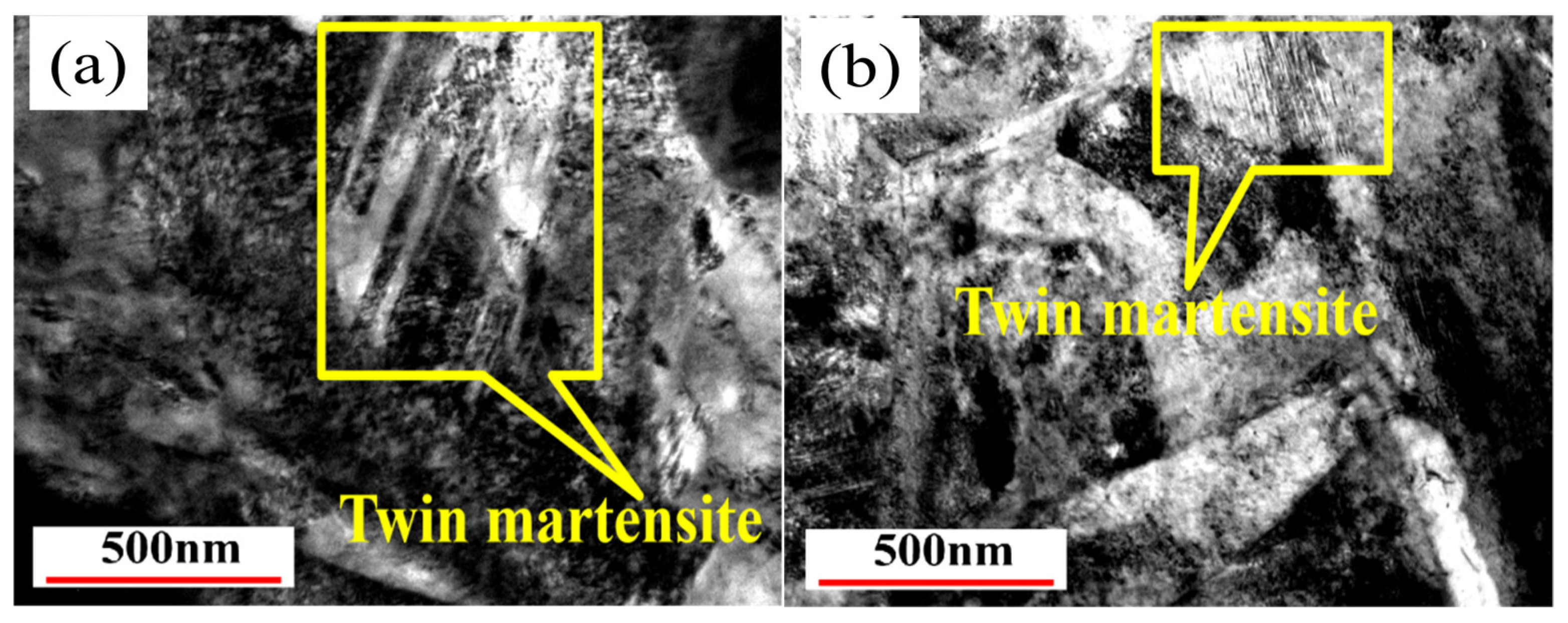
The category and morphology of martensite vary significantly with the carbon content. Generally, in low-carbon steels (≤0.25%), plate martensite with dislocation structure is mainly formed after quenching. As the carbon content increases (≥0.3%), the volume expansion induced by phase transformation during quenching is higher, leading to more severe lattice distortion and promoting the preferential growth of martensite variants, thus forming twinned martensite. Twinned martensite is a high-strength and low-plasticity structure, and the areas where it is located are usually high-stress-concentration regions in the steel. Hydrogen is more likely to accumulate in twinned martensite, causing hydrogen embrittlement [84,85]. As shown in Figure 23, twinned martensite is abundant and relatively coarse in scheme 1#, while in scheme 2#, the amount of twinned martensite is small and the size is very small. Analysis indicates that the addition of Nb to refine the microstructure promotes the formation of martensite variants along more orientations during quenching, increases the stacking fault energy of austenite, makes the phase transformation during quenching more likely to occur through slip mechanisms rather than twinning mechanisms, and facilitates the coordination of quenching strain, thus significantly reducing the content of twinned martensite [86,87].

5. Conclusions

  • To investigate the effect of microalloying on hydrogen embrittlement resistance of hot-stamped steels with strength levels of 1.8 GPa and above, six schemes were designed based on the conventional 34MnB5 grade (scheme 1#: no alloying; scheme 2#: 0.05% Nb; scheme 3#: 0.1% Nb; scheme 4#: 0.05% V; scheme 5#: 0.1% V; scheme 6#: 0.05% Nb + 0.05% V). Multiple comparative tests on hydrogen embrittlement resistance were conducted on quenched specimens from all six schemes. In U-shaped constant-strain bending tests, Nb-containing specimens exhibited fewer fractures within 300 h. In slow strain rate tensile tests (SSRT), Nb-containing specimens showed lower elongation loss, smaller areas of hydrogen-induced brittle fracture on fracture surfaces, and more pronounced ductile fracture characteristics. The ranking of hydrogen embrittlement resistance among the six schemes was scheme 3# > scheme 6# > scheme 2# > scheme 5# > scheme 4# > scheme 1#. The hydrogen embrittlement resistance of V-containing specimens was only slightly better than that of the non-microalloyed scheme, but significantly inferior to that of Nb-containing schemes.
  • Microstructural characterization results indicated that Nb exhibits a much stronger effect than V in refining and homogenizing martensite microstructure. The higher temperature range for second-phase precipitation, stronger driving force for grain boundary diffusion, lower austenite grain boundary diffusion coefficient, and weaker tendency for high-temperature coarsening of precipitates are the fundamental reasons why Nb has superior ability to pin austenite grain boundaries at elevated temperatures, thereby achieving better refinement and homogenization effects. Furthermore, the microstructural refinement and homogenization induced by Nb addition are even greater than that achieved by combined Nb and V additions. Additionally, within the concentration range of 0–0.1%, the amount of Nb added shows a positive correlation with the degree of microstructural refinement and homogenization, providing important guidance for alloy design in developing microalloyed hydrogen embrittlement-resistant hot-stamped steels.
  • First, by significantly refining the martensitic microstructure through Nb addition, the density of geometrically necessary dislocations (GNDs) in the matrix is notably reduced, which helps decrease lattice distortion and thus local stress concentrations, suppressing the formation of high-dislocation-density pathways for H diffusion and in-situ hydrogen-induced crack initiation. Second, the refined martensite structure increases the number of interfaces in the matrix, particularly enhancing the proportion of high-angle grain boundaries, allowing the inhibitory effect of low-angle boundaries on H enrichment and diffusion, as well as the trapping capacity and increased complexity of H diffusion paths provided by high-angle boundaries, to be more effectively realized. Third, Nb addition reduces the number of Σ3 grain boundaries via two mechanisms—reducing austenite twin inheritance and promoting randomization of martensite variants—thereby mitigating their negative impact on martensite’s hydrogen embrittlement resistance. Fourth, the refined martensite microstructure significantly reduces the texture intensity of the matrix and enhances the randomness of martensite lath orientations, more effectively hindering H enrichment and diffusion, and delaying the initiation and propagation of hydrogen-induced cracks. Moreover, Nb promotes the formation of martensite variants along multiple orientations during quenching, increases the stacking fault energy (SFE) of austenite, favors phase transformation via slip rather than twinning during quenching, and coordinates quenching strain, thereby significantly reducing the content of twinned martensite and further lowering localized stress concentrations. These multiple factors work synergistically, ultimately resulting in significantly superior hydrogen embrittlement resistance in Nb-containing steels compared to other schemes.

Author Contributions

Conceptualization, Y.F.; methodology, Y.F.; validation, Y.F., G.H. and H.L.; formal analysis, Y.F.; investigation, J.H., K.L., W.L., H.S., J.B. and J.Z.; resources, C.Y. and H.L.; data curation, Y.F., W.L., J.H., J.B. and J.Z.; writing—original draft preparation, Y.F.; writing—review and editing, Y.F., G.H., J.H., C.Y., H.S. and J.B.; visualization, Y.F., J.Z. and K.L.; supervision, G.H. and H.L.; project administration, G.H.; funding acquisition, G.H. All authors have read and agreed to the published version of the manuscript.

Funding

The authors acknowledge support from the Sub project of China’s Key R&D Program (grant nos. 2016YFB0101605 and 2017YFB0304405), the Chongqing Natural Science Foundation (grant no. CSTB2023NSCQ-MSX0790), and the Chongqing Key Industry R&D Plan Project (grant nos. cstc2018jszx-cyzdX0076 and cstc2018jszx-cyzdX0082).

Data Availability Statement

The original contributions presented in this study are included in the article. Further inquiries can be directed to the corresponding authors.

Conflicts of Interest

Authors Yi Feng, Jianing Bao, and Junping Zhang were employed by the company China Automotive Engineering Research Institute Co., Ltd., author Hongzhou Lu was employed by the company CITIC-CBMM Microalloying Technical Center, CITIC Metal Co., Ltd., and author Cansheng Yu was employed by the company Pangang Group Research Institute Co., Ltd. The remaining authors declare that the research was conducted in the absence of any commercial or financial relationships that could be construed as a potential conflict of interest.

References

  1. Zeran, H.; Yi, L.; Qi, H.; Wang, J. Low-Carbon-Emission Hot Stamping: A Review from the Perspectives of Steel Grade, Heating Process, and Part Design. Automot. Innov. 2023, 6, 324–339. [Google Scholar] [CrossRef] [Scilit]
  2. Xie, D.; Zhuang, W.; Wang, N.; Shi, H.; Wang, P.; Liu, Y.; Chen, Y. Review on Hot Stamping Process and Equipment of High Strength Steel Sheet. J. Mech. Eng. 2022, 58, 319–338. [Google Scholar] [CrossRef] [Scilit]
  3. Jin, X.; Gong, Y.; Han, X.; Du, H.; Ding, W.; Zhu, B.; Zhang, Y.; Feng, Y.; Ma, M.; Liang, B.; et al. A Review of Current State and Prospect of the Manufacturing and Application of Advanced Hot Stamping Automobile Steels. Acta Metall. Sin. 2020, 56, 411–428. [Google Scholar]
  4. Song., Y.; Li., Y.; Lu., J.; Hua., L.; Gu., Y.; Yang, Y. Strengthening and toughening mechanisms of martensite-bainite microstructure in 2 GPa ultra-high strength steel during hot stamping. Sci. China Technol. Sci. 2025, 68, 1520201. [Google Scholar] [CrossRef] [Scilit]
  5. Feng, Y.; Huang, G.; Lu, H.; Zhang, L.; Pu, X. Performance Verification of Microalloyed Ultra High Strength for Hot Stamped Door Crash Beam. Automob. Technol. Mater. 2023, 8, 29–37. [Google Scholar]
  6. Ma, M.T.; Li, K.J.; Si, Y.; Cao, P.J.; Lu, H.Z.; Guo, A.M.; Wang, G.D. Hydrogen embrittlement of advanced high-strength steel for automobile application: A review. Acta Metall. Sin. (Engl. Lett.) 2023, 36, 1144–1158. [Google Scholar] [CrossRef] [Scilit]
  7. Zhao, X.; Zhang, Y.; Wang, C.; Hui, W. Effect of heating temperature on the hydrogen embrittlement susceptibility in hot stamped medium-Mn steel. J. Iron Steel Res. Int. 2024, 31, 849–860. [Google Scholar]
  8. Koyama, M.; Akiyama, E.; Sawaguchi, T.; Raabe, D.; Tsuzaki, K. Hydrogen-induced cracking at grain and twin boundaries in an Fe–Mn–C austenitic steel. Scr. Mater. 2012, 66, 459–462. [Google Scholar] [CrossRef] [Scilit]
  9. Okayasu, M.; Yang, L. Influence of microstructure on the mechanical properties and hydrogen embrittlement characteristics of 1800 MPa grade hot-stamped 22MnB5 steel. J. Mater. Sci. 2019, 54, 5061–5073. [Google Scholar] [CrossRef] [Scilit]
  10. Yoo., J.; Mc, J.; Mc, J.; Kim., S.; Oh., J.; Bian., J.; Ss, S.; Lee, S. Effects of Ti alloying on resistance to hydrogen embrittlement in (Nb plus Mo)-alloyed ultra-high-strength hot-stamping steels. Mater. Sci. Eng. A 2020, 791, 139763. [Google Scholar] [CrossRef] [Scilit]
  11. Shi., R.; Ma., Y.; Wang., Z.; Gao., L.; Pang, X. Atomic-scale investigation of deep hydrogen trapping in NbC/α-Fe semi-coherent interfaces. Acta Mater. 2020, 200, 686–698. [Google Scholar] [CrossRef] [Scilit]
  12. Nagumo, M.; Nakamura, M.; Takai, K. Hydrogen thermal desorption relevant to delayed-fracture susceptibility of high-strength steels. Metall. Mater. Trans. A 2001, 32, 339–347. [Google Scholar] [CrossRef] [Scilit]
  13. Koyama, M.; Akiyama, E.; Lee, Y.K.; Raabe, D.; Tsuzaki, K. Hydrogen-assisted failure in a twinning-induced plasticity steel studied under in situ hydrogen charging by electron channeling contrast imaging. Acta Mater. 2013, 61, 4607–4618. [Google Scholar] [CrossRef] [Scilit]
  14. Chen, Y.; Zhou, G.-F.; Liu, J.; Huang, F. Influence of precipitates on hydrogen-induced-delayed-cracking behavior of hot stamping steel. Trans. Mater. Heat Treat. 2019, 40, 112–122. [Google Scholar]
  15. Liu, H. Study on hydrogen embrittlement resistance of Ti-microalloying hot forming steel for automobile. Iron Steel Vanadium Titan. 2022, 43, 178–183. [Google Scholar]
  16. Li, X.; Ma, X.; Zhang, J.; Akiyama, E.; Wang, Y.; Song, X. Review of Hydrogen Embrittlement in Metals: Hydrogen Diffusion, Hydrogen Characterization, Hydrogen Embrittlement Mechanism and Prevention. Acta Metall. Sin. (Engl. Lett.) 2020, 33, 759–773. [Google Scholar] [CrossRef] [Scilit]
  17. Koyama, M.; Akiyama, E.; Lee, Y.-K.; Raabe, D.; Tsuzaki, K. Hydrogen-assisted decohesion and localized plasticity in dual-phase steel. Acta Mater. 2014, 70, 174–187. [Google Scholar] [CrossRef] [Scilit]
  18. Bhadeshia, H.K.D.H. Prevention of hydrogen embrittlement in steels. ISIJ Int. 2016, 56, 24–36. [Google Scholar] [CrossRef] [Scilit]
  19. Kim, H.J. Effects of prior austenite grain size on hydrogen delayed fracture of hot-stamped boron martensitic steel. Metall. Mater. Trans. A 2020, 51, 237–251. [Google Scholar] [CrossRef] [Scilit]
  20. Zhao, W.; Chen, W.; Zhao, Z.; Kuang, S.; Liu, J.; Sun, L. Study on hydrogen induced delayed fracture of 1500 and 2000MPa hot-stamping steels. J. Iron Steel Res. 2022, 34, 815–824. [Google Scholar]
  21. Morito, S.; Huang, X.; Furuhara, T.; Maki, T.; Hansen, N. The morphology and crystallography of lath martensite in alloy steels. Acta Mater. 2006, 54, 5323–5331. [Google Scholar] [CrossRef] [Scilit]
  22. Zhong., R.; Zhao., J.; Xie., Z.; Han., P.; Wang., H.; Wang., J.; Shang, C. New insights from crystallography into the effect of boundaries on hydrogen embrittlement susceptibility of a 1000 MPa grade heavy gauge high-strength low-alloy steel. Corros. Sci. 2025, 249, 112866. [Google Scholar] [CrossRef] [Scilit]
  23. Yang, X.; Xue, Y.; Yang, S.; Huang, M. Enhancing the hydrogen embrittlement resistance of 304 steel by grain boundary engineering. Int. J. Mater. Res. 2020, 111, 995–1001. [Google Scholar] [CrossRef] [Scilit]
  24. Mirzaei., A.; Pd, H.; Ma., X.; Vk, P.; Farabi., E.; Gs, R.; Beladi, H. The role of parent austenite grain size on the variant selection and intervariant boundary network in a lath martensitic steel. Mater. Sci. Eng. A 2024, 889, 145793. [Google Scholar] [CrossRef] [Scilit]
  25. Luo, H.; Shi, J.; Wang, C.; Cao, W.; Sun, X.; Liu, Q. Experimental and numerical study on geometrically necessary dislocations and non-homogeneous mechanical properties of the martensitic transformation. Acta Mater. 2011, 59, 4002–4014. [Google Scholar] [CrossRef] [Scilit]
  26. Shiqi, Z.; Jifang, W.; Qiyue, Z.; Jing, L.; Feng, H.; Yunhua, H.; Xiaogang, L. Dual role of nanosized NbC precipitates in hydrogen embrittlement susceptibility of lath martensitic steel. Corros. Sci. 2020, 164, 108345. [Google Scholar] [CrossRef] [Scilit]
  27. Liu, G.; Gan, Y.; Liu, C.; Ma, M.; Wu, J.; Yang, Y.; Hu, C. Development of Nb–V microalloyed hot forming steel based on 22MnB5. Heat Treat. Met. 2021, 46, 109–113. [Google Scholar]
  28. Chen, W. Microstructure and Properties Control and Hydrogen Induceddelayed Cracking Behavior of Ultrahigh Strength Hot-Stamped Steel. Ph.D. Thesis, University of Science and Technology Beijing, Beijing, China, 2022. [Google Scholar]
  29. Lintao, G.; Yan, Z.; Yi, F.; Mingtu, M.; Hongzhou, L.; Kun, T.; Po-Han, C.; Aimin, G.; Jian, B.; Jer-Ren, Y.; et al. Study on the improving effect of Nb-V microalloying on the hydrogen induced delayed fracture property of 22MnB5 press hardened steel. Mater. Des. 2023, 227, 111763. [Google Scholar] [CrossRef] [Scilit]
  30. Mingtu, M.; Yan, Z.; Jingwei, L.; Gang, L.; Xiang, T.; Yu, C. The effect of composite microalloying on the performance of hot press forming B-pillars. In Proceedings of the 7th International Conference on Advanced High Strength Steel and Press Hardening; Springer Nature: Berlin, Germany, 2024. [Google Scholar]
  31. T/CSAE 155-2020; U-Shaped Constant Bending Load Test Method for Hydrogen Induced Delayed Fracture Sensitivity of Ultra High Strength Automobile Steel Plate. CSAE: Beijing, China, 2015.
  32. Wang, M.; Akiyama, E.; Tsuzaki, K. Determination of the critical hydrogen concentration for delayed fracture of high strength steel by constant load test and numerical calculation. Corros. Sci. 2006, 48, 2189–2202. [Google Scholar] [CrossRef] [Scilit]
  33. Xu, Y.; Hui, W.; Fang, B.; Hua, Z.; Zhang, Y.; Zhao, X. Effect of low-temperature ausforming on hydrogen-induced delayed fracture of high str ength bolt steel. Chin. J. Eng. 2025, 47, 1989–2001. [Google Scholar]
  34. McQueen, H.J.; Yue, S.; Ryan, N.D.; Fry, E. Hot working characteristics of steels in austenitic state. J. Mater. Process. Technol. 1995, 53, 293–310. [Google Scholar] [CrossRef] [Scilit]
  35. Xinyao, Z.; Chen, C.; Qian, L.; Ting, Z.; Dongyun, S.; Sha, L.; Zhinan, Y.; Bo, L.; Fucheng, Z. Improved hardenability of medium-carbon steel by tuning V distribution at grain boundaries. J. Mater. Sci. Technol. 2026, 258, 228–241. [Google Scholar] [CrossRef] [Scilit]
  36. Yu, V.; Novikov. On zener pinning in 3-D polycrystals. Scr. Mater. 2000, 42, 439–443. [Google Scholar] [CrossRef] [Scilit]
  37. Medina, S.F. From heterogeneous to homogeneous nucleation for precipitation in austenite of microalloyed steels. Acta Mater. 2015, 84, 202–216. [Google Scholar] [CrossRef] [Scilit]
  38. Shang, J.X.; Wang, C.Y. Electronic effects of alloying elements Nb and V on body-centred-cubic Fe grain boundary cohesion. J. Phys.-Condens. Matter 2001, 13, 9635–9644. [Google Scholar] [CrossRef] [Scilit]
  39. Zaefferer, S.; Ohlert, J.; Bleck, W. A study of microstructure, transformation mechanisms and correlation between microstructure and mechanical properties of a low alloyed TRIP steel. Acta Mater. 2004, 52, 2765–2778. [Google Scholar] [CrossRef] [Scilit]
  40. Andrade, H.L.; Akben, M.G.; Jonas, J.J. Effect of molybdenum, niobium, and vanadium on static recovery and recrystallization and on solute strengthening in microalloyed steels. Metall. Trans. A 1983, 14, 1967–1977. [Google Scholar] [CrossRef] [Scilit]
  41. Dan, W.; Fuming, W.; Jin, C.; Changrong, L. Effect of Nb and V on austenite grain growth behavior of the Cr-Mo-V steel for brake discs. High Temp. Mater. Proc. 2018, 37, 899–907. [Google Scholar] [CrossRef] [Scilit]
  42. Zajac, S.; Lagneborg, R.; Siwecki, T. The role of nitrogen in microalloyed steels. In Proceedings of the International Conference on Microalloying in Steels, Pittsburgh, PA, USA, 11–14 June 1995; pp. 321–330. [Google Scholar]
  43. Murakami, Y.; Kanezaki, T.; Mine, Y. Hydrogen effect against hydrogen embrittlement. Metall. Mater. Trans. A 2010, 41, 2548–2562. [Google Scholar] [CrossRef] [Scilit]
  44. Xie, Z.J.; Shang, C.J.; Wang, X.L.; Wang, X.M.; Han, G.; Misra, R.D.K. Microstructure-property relationship in a low carbon Nb-B bearing ultra-high strength steel by direct quenching and subsequent tempering. Mater. Sci. Eng. A 2018, 727, 200–209. [Google Scholar] [CrossRef] [Scilit]
  45. Xiaofang, W.; Chuanwei, L.; Zhifeng, Z.; Xiaoli, Z.; Daming, T.; Guanghua, Y.; Lizhan, H.; Jianfeng, G. Tailoring the microstructure and mechanical properties of H13 steel by controlling the pre-precipitation of VC carbides from austenite. J. Mater. Res. Technol. 2024, 33, 9614–9621. [Google Scholar] [CrossRef] [Scilit]
  46. Roine, A. Activities of As, Sb, Bi, and Pb in copper mattes—Impurity elimination. Metall. Trans. B 1987, 18, 213–223. [Google Scholar] [CrossRef] [Scilit]
  47. Hashimoto, S.; Ikeda, S.; Sugimoto, K.I.; Miyake, S. Nb and Mo addition to 0.2%C-1.5%Si-1.5%Mn steel for the improvement of hydrogen embrittlement properties. ISIJ Int. 2004, 44, 1590–1598. [Google Scholar]
  48. Zajac, S.; Schwinn, V.; Tacke, K.H. Characterisation and Quantification of Complex Bainitic Microstructures in High and Ultra-High Strength Linepipe Steels. Mater. Sci. Forum 2005, 500–501, 387–394. [Google Scholar] [CrossRef] [Scilit]
  49. Zajac, S.; Siwecki, T.; Hutchinson, B.; Attlegard, M. Strengthening mechanisms in vanadium microalloyed steels intended for long products. ISIJ Int. 1998, 38, 1130–1139. [Google Scholar] [CrossRef] [Scilit]
  50. Ouchi, C.; Sampei, T.; Kozasu, I. The effect of hot rolling condition and chemical composition on the onset temperature of γ to α transformation after hot rolling. Trans. ISIJ 1982, 22, 214–222. [Google Scholar] [CrossRef] [Scilit]
  51. Taketomi, S.; Matsumoto, R.; Miyazaki, N. Atomistic study of hydrogen distribution and diffusion around a {112}<111> edge dislocation in alpha iron. Acta Mater. 2008, 56, 3761–3769. [Google Scholar] [CrossRef] [Scilit]
  52. Mine, Y.; Horita, Z.; Murakami, Y. Effect of high-pressure torsion on hydrogen trapping in Fe–0.01 mass% C and type 310S austenitic stainless steel. Acta Mater. 2010, 58, 649–657. [Google Scholar] [CrossRef] [Scilit]
  53. Ueji, R.; Tsuji, N.; Minamino, Y.; Koizumi, Y. Ultragrain refinement of plain low carbon steel by cold-rolling and annealing of martensite. Acta Mater. 2002, 50, 4177–4189. [Google Scholar] [CrossRef] [Scilit]
  54. Kennett, S.C.; Krauss, K.O.; Findley. Prior austenite grain size and tempering effects on the dislocation density of low-C Nb–Ti microalloyed lath martensite. Scr. Mater. 2015, 107, 123–126. [Google Scholar] [CrossRef] [Scilit]
  55. Feng, Z.; Li, B.; Zhang, D.; Yan, L.; Xu, T. Effects of V-N microalloying on microstructure and properties of high-strength shipbuilding steel. Iron Steel 2026, 61, 160–171. [Google Scholar]
  56. Wang, C.; Wang, M.; Shi, J.; Hui, W.; Dong, H. Effect of microstructural refinement on the toughness of low carbon martensitic steel. Scr. Mater. 2008, 58, 492–495. [Google Scholar] [CrossRef] [Scilit]
  57. He, B.B.; Hu, B.; Yen, H.W.; Cheng, G.J.; Wang, Z.K.; Luo, H.W.; Huang, M.X. High dislocation density–induced large ductility in deformed and partitioned steels. Science 2017, 357, 1029–1032. [Google Scholar] [CrossRef] [Scilit] [PubMed]
  58. Wei, C.; Li, K.; Yang, W.; Zhu, X.; Yang, Q. Effect of Grain Size on Low Cycle Fatigue Behavior and Microstructure after Fatigue of IF Steel. Mater. Mech. Eng. 2023, 47, 23–28, 38. [Google Scholar]
  59. Calcagnotto, M.; Ponge, D.; Raabe, D. Effect of grain refinement to 1μm on strength and toughness of dual-phase steels. Mater. Sci. Eng. A 2010, 527, 7832–7840. [Google Scholar] [CrossRef] [Scilit]
  60. Murugesan, D.; Dhua, S.K.; Kumar, S.; Thakur, B.N. Development of hot stamping grade steel with improved impact toughness by Nb microalloying. Mater. Today Proc. 2018, 5, 16887–16892. [Google Scholar] [CrossRef] [Scilit]
  61. Martínez-Pañeda, E.; del Busto, S.; Niordson, C.F.; Betegón, C. Strain gradient plasticity modeling of hydrogen diffusion to the crack tip. Int. J. Hydrogen Energy 2016, 41, 10265–10274. [Google Scholar] [CrossRef] [Scilit]
  62. Koyama, M.; Akiyama, E.; Lee, Y.K.; Raabe, D.; Tsuzaki, K. Overview of hydrogen embrittlement in high-Mn steels. Int. J. Hydrogen Energy 2017, 42, 12706–12723. [Google Scholar] [CrossRef] [Scilit]
  63. Depover, T.; Van den Eeckhout, E.; Verbeken, K. The impact of hydrogen on the ductility loss of bainitic Fe–C alloys. Mater. Sci. Eng. A 2016, 673, 99–107. [Google Scholar]
  64. Wang, S.; Martin, M.L.; Robertson, I.M.; Sofronis, P. Effect of hydrogen environment on the separation of Fe grain boundaries. Acta Mater. 2016, 107, 279–288. [Google Scholar] [CrossRef] [Scilit]
  65. Nagumo, M. Fundamentals of Hydrogen Embrittlement; Springer: Singapore, 2016; pp. 45–80. [Google Scholar]
  66. Xiaodong, L.; Kazuho, O.; Ivan, G.-U.; Akinobu, S. Effects of prior austenite grain size on hydrogen embrittlement behavior in high-strength martensitic steel. Mater. Sci. Eng. A 2026, 950, 149539. [Google Scholar] [CrossRef] [Scilit]
  67. Abdelrahman, H.; Byungki, K.; Kim, V.; Depover, T. The effect of grain boundary misorientation on hydrogen flux using a phase-field based diffusion and trapping model. Adv. Eng. Mater. 2024, 26, 2401561. [Google Scholar] [CrossRef] [Scilit]
  68. Zhu, S.; Li, Y.; Cao, P.; Liao, Y.; Cao, F.; Li, G. Research Progress on Hydrogen Embrittlement Sensitivity of Pipeline Steel for Hydrogen-Blended Natural Gas Transportation. Mater. Mech. Eng. 2025, 49, 12–24. [Google Scholar]
  69. Zemin, X.; Lin, C.; Kai, X.; Chengyang, H.; Kaiming, W. Effect of alloying solutes on hydrogen segregation at pure iron Σ3(111) grain boundary: First-principles calculation. Int. J. Hydrogen Energy 2024, 84, 321–333. [Google Scholar] [CrossRef] [Scilit]
  70. Runsheng, W.; Lin, C.; Chaochao, Y.; Wenjing, L.; Kaiming, W. The effects of hydrogen and vacancy on the tensile deformation behavior of Σ3 symmetric tilt grain boundaries in pure Fe. Int. J. Hydrogen Energy 2023, 48, 30930–30948. [Google Scholar] [CrossRef] [Scilit]
  71. Feng, Y.; Song, L.; Ma, M.; Zhao, Y.; Zhang, J.; Sun, D. The Study Status of Hydrogen Induced Delayed Fracture of High Strength Steel. In Proceedings of the Conference for Automotive EVI & Hydrogen Embrittlement High Strength Steels, Beijing, China, 14–17 December 2017; pp. 285–304. [Google Scholar]
  72. Tingshu, C.; Motomichi, K.; Takahiro, C.; Eiji, A.; Kenichi, T. Mesoscale quantification of grain boundary character and local plasticity in hydrogen-assisted intergranular and intergranular-like cracking paths in tempered martensitic steel. Mater. Sci. Eng. A 2023, 886, 145718. [Google Scholar] [CrossRef] [Scilit]
  73. Kitahara, H.; Ueji, R.; Tsuji, N.; Minamino, Y. Crystallographic features of lath martensite in low-carbon steel. Acta Mater. 2006, 54, 1279–1288. [Google Scholar] [CrossRef] [Scilit]
  74. Miyamoto, G.; Shibata, A.; Maki, T.; Furuhara, T. Precise measurement of strain accommodation in austenite matrix surrounding martensite in ferrous alloys by electron backscatter diffraction analysis. Acta Mater. 2009, 57, 1120–1131. [Google Scholar] [CrossRef] [Scilit]
  75. Gey, N.; Petit, B.; Humbert, M. Electron backscattered diffraction study of ε/α′ martensitic variants induced by plastic deformation in 304 stainless steel. Metall. Mater. Trans. A 2005, 36, 3291–3299. [Google Scholar] [CrossRef] [Scilit]
  76. Xinfeng, L.; Jin, Z.; Eiji, A.; Yanfei, W.; Qizhen, L. Microstructural and crystallographic study of hydrogen-assisted cracking in high strength PSB1080 steel. Int. J. Hydrogen Energy 2018, 43, 17898–17911. [Google Scholar] [CrossRef] [Scilit]
  77. Tomoka, H.; Seiya, A.; Shoma, O.; Kenichi, T. Crack initiation and propagation behavior of hydrogen-induced quasi-cleavage fracture in X80 pipeline steel with stress concentration. ISIJ Int. 2021, 61, 2654–2665. [Google Scholar] [CrossRef] [Scilit]
  78. Morito, S.; Saito, H.; Ogawa, T.; Furuhara, T.; Maki, T. Effect of austenite grain size on the morphology and crystallography of lath martensite in low carbon steels. ISIJ Int. 2005, 45, 91–94. [Google Scholar] [CrossRef] [Scilit]
  79. Bhadeshia, H.K.D.H. Bainite in Steels: Transformations, Microstructure and Properties, 2nd ed.; IOM Communications: London, UK, 2001; pp. 117–145. [Google Scholar]
  80. Santofimia, M.J.; Zhao, L.; Petrov, R.; Kwakernaak, C.; Sloof, W.G.; Sietsma, J. Microstructural development during the quenching and partitioning process in a newly designed low-carbon steel. Acta Mater. 2011, 59, 6059–6068. [Google Scholar] [CrossRef] [Scilit]
  81. Speer, J.G.; Matlock, D.K.; De Cooman, B.C.; Schroth, J.G. Carbon partitioning from austenite during quenching and partitioning (Q&P) processing. Acta Mater. 2003, 51, 2611–2622. [Google Scholar]
  82. Beladi, H.; Chao, Q.; Rohrer, G.S. Variant selection and intervariant crystallographic planes distribution in martensite in a hypoeutectoid Ti–6Al–4V alloy. Acta Mater. 2014, 80, 478–489. [Google Scholar] [CrossRef] [Scilit]
  83. Mohammad, M.; Cleiton Carvalho, S.; Miloslav, B.; Duberney Hincapie, L.H.F.G.; de, A. Role of crystallographic texture on the improvement of hydrogen-induced crack resistance in API 5L X70 pipeline steel. Int. J. Hydrogen Energy 2017, 42, 1318–1326. [Google Scholar] [CrossRef] [Scilit]
  84. Krauss, G. Martensite in steel: Strength and structure. Mater. Sci. Eng. A 1999, 273–275, 40–57. [Google Scholar] [CrossRef] [Scilit]
  85. Chao, H.; Cuiwei, D.; Xiaogang, L. Microstructural evolution and hydrogen embrittlement in simulated reheated coarse-grained heat-affected zone of a high-strength naval steel. Int. J. Hydrogen Energy 2024, 88, 1034–1047. [Google Scholar] [CrossRef] [Scilit]
  86. Chakraborty, A.; Webster, R.F.; Primig, S. Lath martensite substructure evolution in low-carbon microalloyed steels. J. Mater. Sci. 2022, 57, 10359–10378. [Google Scholar] [CrossRef] [Scilit]
  87. Thrun, M.M.; Euser, V.K.; Clarke, A.J.; Clarke, K.D. Tuning austenite stability through prior microstructure control in a low-alloy Q&P steel. Materialia 2024, 38, 102261. [Google Scholar] [CrossRef] [Scilit]
Figure 1. Annealing process flowchart.
Metals 16 00932 g001
Figure 2. Annealed sheet.
Metals 16 00932 g002
Figure 3. Hot forming system: (a) heating furnace and (b) plate quenching mold.
Metals 16 00932 g003
Figure 4. Structure of U-shaped constant-strain bending test specimen and bending fixture [31].
Metals 16 00932 g004
Figure 5. Examples of the clamping process and the appearance after clamping of U-shaped constant-strain bending test specimens [31].
Metals 16 00932 g005
Figure 6. Soaking process of U-shaped constant-strain bending test specimens.
Metals 16 00932 g006
Figure 7. SSRT specimen size specifications and equipment: (a) sample specifications and (b) test equipment.
Metals 16 00932 g007
Figure 8. Results of U-shaped constant-strain bending tests on quenched specimens of different schemes—proportion of fractured specimens.
Metals 16 00932 g008
Figure 9. Hydrogen-charged slow strain rate tensile curves of quenched specimens under different schemes: (a) schemes 1 to 3# and (b) schemes 4 to 6#.
Metals 16 00932 g009
Figure 10. Macroscopic fracture surface morphology (SEM) of hydrogen-charged slow strain rate tensile specimens in quenched state under different schemes: (a) scheme 1#; (b) scheme 2#; (c) scheme 3#; (d) scheme 4#; (e) scheme 5#; and (f) scheme 6#.
Metals 16 00932 g010
Figure 11. Morphology of hydrogen-induced fracture regions of quenched specimens under different schemes (SEM): (a) scheme 1#; (b) scheme 2#; (c) scheme 3#; (d) scheme 4#; (e) scheme 5#; and (f) scheme 6#.
Metals 16 00932 g011
Figure 12. The size and morphology characteristics of the original austenite and the martensite after quenching of the samples from different schemes: (a,d): scheme 1#; (b,e): scheme 2#; (c,f): scheme 3#; (g,j): scheme 4#; (h,k): scheme 5#; and (i,l): scheme 6#.
Metals 16 00932 g012
Figure 13. The austenite grain sizes of schemes #1 and #2 under high-temperature conditions: (a) scheme 1# and (b) scheme 2#.
Metals 16 00932 g013
Figure 14. Nb (C, N) distributed along the original austenite grain boundaries in the quenched specimen (scheme 2#).
Metals 16 00932 g014
Figure 15. The variation of the area fraction of different-sized martensite laths in the quenched specimens of schemes 1# to 6#: (a) scheme 1#; (b) scheme 2#; (c) scheme 3#; (d) scheme 4#; (e) scheme 5#; and (f) scheme 6#.
Metals 16 00932 g015
Figure 16. Comparison of the size and uniformity of martensite lath bundles in quenched samples of scheme 2#, 3#, and 6#: (a) scheme 2#; (b) scheme 3#; and (c) scheme 6#.
Metals 16 00932 g016
Figure 17. Test results of KAM and TEM—high dislocation density regions of quenched samples of schemes 1# and 2#: (a) scheme 1#—KAM; (b) scheme 2#—KAM; (c) scheme 2#—high dislocation zone at interface; and (d) scheme 2#—dislocation cell.
Metals 16 00932 g017
Figure 18. Test results of IQ for quenched specimens of schemes 1# to 6#: (a) scheme 1#; (b) scheme 2#; (c) scheme 3#; (d) scheme 4#; (e) scheme 5#; and (f) scheme 6#.
Metals 16 00932 g018aMetals 16 00932 g018b
Figure 19. Statistical results of interface orientation angles in quenched samples of scheme 1# and scheme 2# (EBSD): (a) scheme 1# and (b) scheme 2#.
Metals 16 00932 g019
Figure 20. Statistical results of the quantity proportion of different interface orientation angles in quenched samples of schemes 1# to 6# (EBSD): (a) scheme 1#; (b) scheme 2#; (c) scheme 3#; (d) scheme 4#; (e) scheme 5#; and (f) scheme 6#.
Metals 16 00932 g020
Figure 21. The quantity of Σ3 grain boundaries in the quenched samples of schemes 1# and 2# (EBSD): (a) scheme 1# and (b) scheme 2#.
Metals 16 00932 g021
Figure 22. Texture characteristic information of quenched samples of schemes 1# and 2# (EBSD): (a) scheme 1#—IPF diagram; (b) scheme 2#—IPF diagram; (c) scheme 1#—ODF diagram; and (d) scheme 2#—ODF diagram.
Metals 16 00932 g022
Figure 23. Twinning martensite in quenched specimens of schemes 1# and 2#: (a) scheme 1# and (b) scheme 2#.
Metals 16 00932 g023
Table 1. Composition scheme (wt%).
ElementCSiMnCrAlBTiNbV
No.
1#0.340.701.501.00≤0.03%0.0030.03--
2#0.340.701.501.00≤0.03%0.0030.030.05-
3#0.340.701.501.00≤0.03%0.0030.030.10-
4#0.340.701.501.00≤0.03%0.0030.03-0.05
5#0.340.701.501.00≤0.03%0.0030.03-0.10
6#0.340.701.501.00≤0.03%0.0030.030.050.05
Table 2. Quasi-static tensile results of samples in quenched state under different schemes.
No.Sample Thickness
(a/mm)
Sample Width
(b/mm)
Yield Strength
(Rel/MPa)
Tensile Strength
(Rm/MPa)
Elongation
(A/%)
1#1.4012.501235.731902.957.06
2#1.4012.501345.041947.827.46
3#1.4012.501359.071964.447.67
4#1.4012.501299.381895.017.09
5#1.4012.501318.381928.087.20
6#1.4012.501300.311907.277.79
Note: The above result data are all the average values of the test data from three specimens.
Table 3. Results of U-shaped constant-strain bending tests on quenched specimens of different schemes.
No.Bending Span: 145 mm, Soaking Time (0.1 mol/L HCL): ≤300 h
(O: No Fracture, ●: Fracture)
1#Group 1#Group 2#Group 3#Group 4#Group 5#
1-11-22-12-23-13-24-14-25-15-2
ResultOO
2#Group 1#Group 2#Group 3#Group 4#Group 5#
1-11-22-12-23-13-24-14-25-15-2
ResultOOOOOO
3#Group 1#Group 2#Group 3#Group 4#Group 5#
1-11-22-12-23-13-24-14-25-15-2
ResultOOOOOOOOO
4#Group 1#Group 2#Group 3#Group 4#Group 5#
1-11-22-12-23-13-24-14-25-15-2
ResultOOOO
5#Group 1#Group 2#Group 3#Group 4#Group 5#
1-11-22-12-23-13-24-14-25-15-2
ResultOOOOO
6#Group 1#Group 2#Group 3#Group 4#Group 5#
1-11-22-12-23-13-24-14-25-15-2
Result--O-O--
Disclaimer/Publisher’s Note: The statements, opinions and data contained in all publications are solely those of the individual author(s) and contributor(s) and not of MDPI and/or the editor(s). MDPI and/or the editor(s) disclaim responsibility for any injury to people or property resulting from any ideas, methods, instructions or products referred to in the content.