Article

Comparative Study on the Weldability and Low-Temperature Toughness of Thick TMCP Steel for Offshore Wind Power Substructures According to Grade and Welding Position


1
Department of Naval Architecture and Ocean Engineering, Chosun University, Gwangju 61452, Republic of Korea
2
Purpose Built Mobility Group, Korea Institute of Industrial Technology, Gwangju 61012, Republic of Korea
*
Author to whom correspondence should be addressed.
These authors contributed equally to this work.
Metals 2026, 16(7), 800; https://doi.org/10.3390/met16070800
Submission received: 22 June 2026 / Revised: 10 July 2026 / Accepted: 14 July 2026 / Published: 16 July 2026

Abstract

As the demand for eco-friendly energy increases, offshore wind power structures are gradually becoming larger to increase power generation capacity, which in turn requires the use of thick TMCP steels and the securing of structural integrity. In this study, multi-pass FCAW was applied to 40 mm thick S355ML and S420ML steels in 2G and 3G welding positions, and the welding conditions for each experiment were designed to simulate actual industrial site construction conditions. After the experiments, tensile, low-temperature impact, and hardness tests were performed on the welded joints, and a comparative analysis was conducted on whether the relevant standards were satisfied and their major characteristics. As a result of the tensile test, tensile strengths exceeding the standard requirements were measured under all conditions, and base metal fracture occurred. In addition, the low-temperature impact test conducted at −50 °C exceeded the standard requirement of 27 J, ensuring sufficient low-temperature toughness, and the Vickers hardness test results were measured to be less than the reference value of 380 HV10. Through this study, the structural integrity and mechanical reliability of multi-pass FCAW welded joints for thick TMCP steel plates were secured.

1. Introduction

Offshore wind power generation is a system that utilizes wind energy acting at sea to convert it into mechanical energy and generate electricity, and it is recognized as a representative type of eco-friendly and renewable energy. In addition, its demand is gradually increasing in accordance with the recent strengthening of emission regulations for global greenhouse gas reduction [1,2,3]. In particular, since wind conditions at sea are superior to those of onshore wind power generation [4], studies on large-capacity power generation towers are being continuously performed [5,6].
Meanwhile, the increase in power generation capacity has inevitably required an increase in the weight and scale of structures, and the substructures to support them have also begun to gradually become larger [7,8]. Such enlargement of structures has come to necessitate more stable materials and joining technologies [9,10], and in particular, offshore wind power generation requires more stringent standards than onshore wind power generation due to conditions such as low-temperature environments caused by seawater, securing fatigue loads caused by continuous waves, and corrosion [11,12].
This type of development has induced the application of high-strength steels, such as TMCP (Thermo-Mechanical Control Process) steel, to prevent an excessive increase in total weight while maintaining structural stability [13,14]. As for the materials used for offshore wind power generation, dedicated steels exist, such as S355ML and S420ML defined in EN10025-4 [15], EN10225 [16], NORSOK M-120 [17], DNV OS B101 [18], etc., and excellent low-temperature impact toughness is required for these steels, and excellent strength and low-temperature impact toughness must also be secured for their welded joints. These types of steels are primarily utilized throughout the substructures of monopile-type offshore wind turbines, as well as in the main legs and braces of jacket-type offshore wind substructures.
Currently, various welding techniques exist that are mainly used in the fabrication of offshore wind substructures, such as FCAW (Flux Cored Arc Welding) [19], SAW (Submerged Arc Welding) [20], and EGW (Electro Gas Welding) [21]. Offshore wind substructures encompass a very diverse range of material thicknesses from 8 to 120 mm, due to which SAW and EGW are essentially used when welding thick or ultra-thick plates, and FCAW is used in a wide thickness range for root welding and repair welding due to weld defects [22,23]. In particular, multi-pass welding is essentially required for materials with heavy thicknesses, and in this case, the management of inter-pass temperature is an important factor because the degradation of weld strength and impact toughness may be induced due to the repetition of continuous heating and cooling cycles during fill and cap welding after the root weld pass [24,25,26,27].
Various studies related to the fabrication of offshore wind substructures using TMCP steels have been performed, among which Mehmanparst et al. attempted to characterize the properties of welded joints of S355 steel used for monopiles by conducting a multi-party collaborative study on the mechanical and fracture properties of the base metal, heat affected zone (HAZ), and weld metal; as a result, the impact strength was measured to be highest in the order of base metal, HAZ, and weld metal, and a trend where the yield strength and hardness consistently increased from the base metal toward the weld metal was observed [28]. In addition, Okenyi et al. applied SAW welding to S355G10 + M structural steel of four different thicknesses—6 mm, 10 mm, 15 mm, and 20 mm—and subsequently performed strength, hardness, deformation, residual stress, and fatigue tests to analyze the difference in welded joint properties depending on the thickness. As a result of the study, the SAW welding process satisfied the quality required for monopiles, and although the tensile strength was higher than that of the base metal, the yield strength was lower than that of the base metal, and it was confirmed that as the thickness increased, the effects of stress concentration and tensile residual stress became greater. However, it was specified that a softening phenomenon with decreased hardness was observed in the intercritical HAZ (ICHAZ) region, identifying it as a potential vulnerability point. Additional analysis revealed a high stress concentration factor at the boundary between the HAZ and the weld metal, suggesting that micro-voids within the HAZ could act as initiation sites for fatigue cracks [20]. In addition, Reisgen et al. and Gook et al. applied a new welding method combining Electron Beam Welding (EBW), Laser-Arc Hybrid Welding (LAHW), and narrow gap SAW to an 80 mm thick S355ML steel plate to present new parameters for meeting the standards, and evaluated the results through cross-sectional observation, analytical approaches, and mechanical property testing [29,30]. Meanwhile, Bunaziv et al. applied LAHW and conventional arc welding methods to a 40 mm thick S355ML steel material and confirmed that, in terms of efficiency and cost, the LAHW technique has higher productivity and excellent efficiency compared to conventional GMAW welding, but has cracks and some quality problems [31]. Furthermore, Wang et al. analyzed 25 mm thick 550 MPa-grade TMCP steels for wind power generation utilizing a Gleeble-3500 thermal–mechanical simulation tester. Their results confirmed that the low-temperature toughness at the centerline of the base metal was lower than that at the surface due to the formation of martensite and M/A constituents caused by continuous band segregation of Mn and C. Additionally, it was verified that the Mn segregation did not diffuse during the welding thermal cycles but inherited into the HAZ, thereby degrading the toughness [32].
Such previous studies mainly comprise evaluation of a single welding technique or comparative evaluation of weldability by welding technique for a single material, fatigue performance evaluation, and analytical approaches to welding techniques. Furthermore, while the previous literature has predominantly focused on S355ML-grade steels, investigations into multi-pass FCAW of heavy-section S420ML TMCP plates remain highly limited. Therefore, this study not only evaluates the suitability of welding conditions for the S420ML grade through a comprehensive mechanical property assessment, but also analyzes the mechanical behaviors of both steel grades under identical welding parameters, while further explicitly comparing the distinct effects resulting from the differences in groove geometries and spatial welding positions. To achieve this, multi-pass FCAW experiments were performed under four distinct conditions using 40 mm thick S355ML and S420ML steel plates to simulate actual offshore wind substructure fabrication site conditions. By applying 2G and 3G welding positions respectively, the structural integrity of the welded joints was evaluated through tensile testing, low-temperature Charpy impact testing at −50 °C, and Vickers hardness measurements, followed by a comparative analysis of the variations induced by both steel grades and welding positions. It was intended to compare the analysis of welded joint strength and behavior due to the groove geometry according to the position, and the effect on low-temperature impact properties due to the difference in conditions during the multi-pass welding process. The results of this study are expected to be utilized as important basic mechanical data for process optimization and structural reliability design of offshore wind substructures that are becoming larger.

2. Materials and Methods

2.1. Materials

The steel materials used for this study are S355ML and S420ML TMCP steels, and the major chemical compositions and mechanical properties of each steel are shown in Table 1. Both materials satisfied the composition ratios presented in EN10025-4 [15], and the tensile strength and impact toughness also satisfied the standard values. S420ML has a higher composition of niobium (Nb) and vanadium (V) compared to S355ML, and it is judged that relatively high strength is achieved through the grain refinement and precipitation strengthening control of the corresponding elements [33,34,35].
Furthermore, the filler metal used for this study was AWS A5.29 E81T1-K2C H4 (1.4 mm) [36]. According to the AWS standards, this filler metal must satisfy a yield strength of 470 MPa or higher, a tensile strength of 550–690 MPa, and an elongation of 19% or higher, and its chemical composition and mechanical properties are presented in Table 2.

2.2. Welding Methods

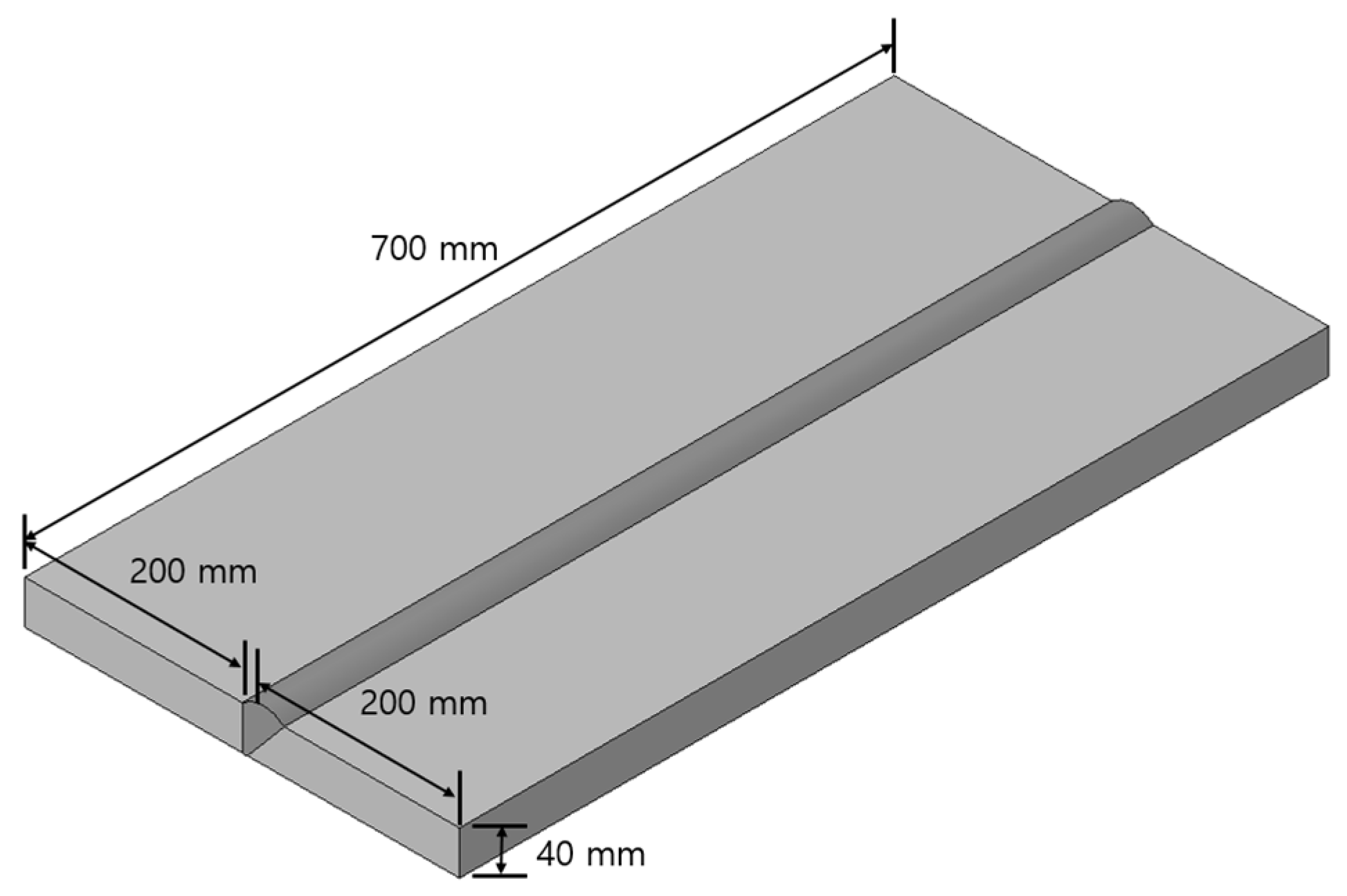
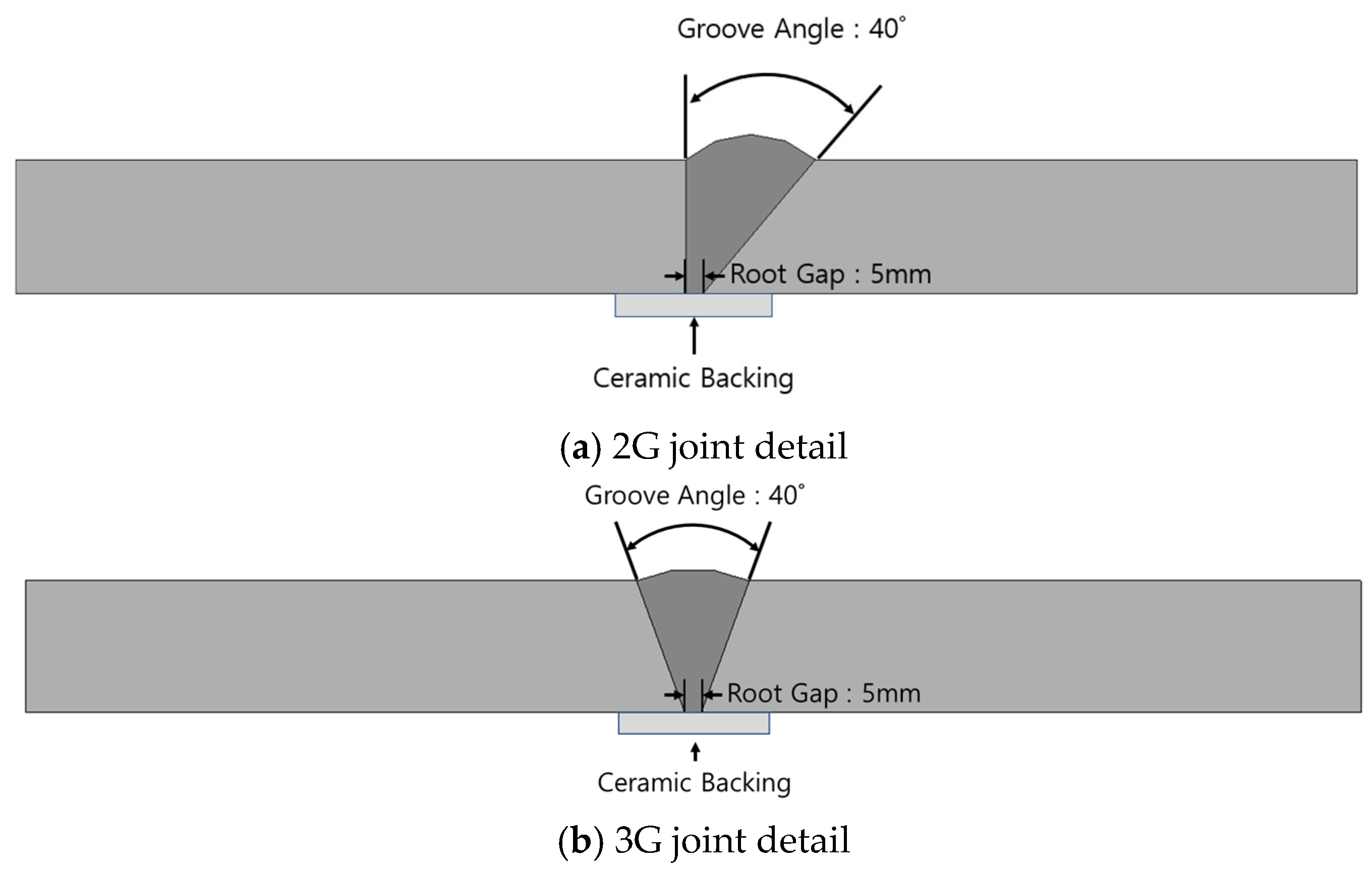
For the welding experiments, the two steel materials, S355ML and S420ML, were machined into specimens with dimensions of 700 × 200 × 40 (width × length × thickness, mm) as shown in Figure 1, and 2G and 3G welding conditions were selected to simulate the actual production process in the field. In addition, for the weld groove for each welding position, a single-bevel groove was applied for 2G welding and a V-groove was applied for 3G welding as shown in Figure 2. The welding conditions for each position were divided into root, fill, and cap sections, and were selected considering the welding and material characteristics by position, and the conditions are listed in Table 3.
The welding conditions for each steel grade and position were designed to achieve a heat input equivalent to actual industrial site conditions, considering the effects of the chemical compositions of the base metals and consumables, as well as the groove geometries for each position. In particular, since S420ML is a higher-strength steel with a higher carbon equivalent compared to S355ML, a relatively higher heat input condition was applied to suppress low-temperature cracking induced by low heat input [37]. All experiments utilized 100% CO2 shielding gas at a flow rate of 25 L/min under DCEP polarity. Prior to welding, the base metal was preheated to 25 °C, and the torch angle was set to 45°. During welding, the current and voltage for each pass were measured using a clamp meter (Fluke-393FC, Fluke Co., Everett, WA, USA), and the inter-pass temperature was monitored using an infrared thermometer (BO-882, Bluetec Co., Daegu, Republic of Korea).

2.3. Mechanical Test

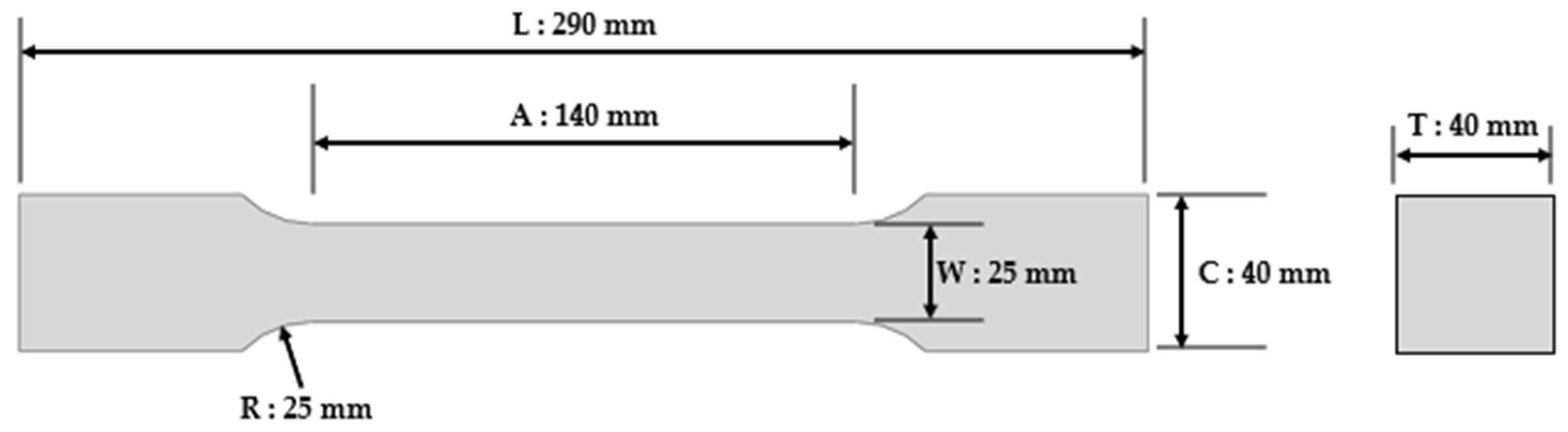
Cross-sectional observation, tensile testing, low-temperature impact testing, and hardness testing were performed on the FCAW specimens. The cross-sectional observation was conducted utilizing GX51 (Olympus Co., Tokyo, Japan) equipment after etching with a 3% nital solution in accordance with ISO 17639:2022 [38] The tensile tests were performed in accordance with the ISO 4136:2022 [39] guidelines, and the specific geometric dimensions of the tensile specimens are schematically illustrated in Figure 3. The tensile evaluation was conducted at room temperature using a universal testing machine (DTU-900MHN, Daekyung Tech & Testers, Incheon, Republic of Korea) on a total of two identical specimens for each configuration. The tests were carried out under displacement control mode at a constant crosshead speed of 20 mm/min, during which the continuous tensile load (N) was recorded. Considering the unique operating environments of heavy-thickness steels for offshore wind power structures, the low-temperature Charpy V-notch impact toughness tests were conducted at −50 °C in strict compliance with the ISO 148-1:2016 [40] standard. For each material and welding position baseline, a total of 12 impact specimens were systematically extracted, consisting of three duplicate replicates from each of the critical notch target locations: the face weld metal, the fusion line (FL), the fusion line +2 mm, and the root weld metal. The transient impact energy (J) was recorded utilizing an impact testing machine (DTU-603B, Daekyung Tech & Testers Co., Incheon, Republic of Korea). Vickers hardness measurements complied with the guidelines of ISO 9015-1 [41] and ISO 6507-1:2018 [42], and were systematically performed across a total of 38 distinct points encompassing the weld metal, heat-affected zone (HAZ), and base metal regions. These cross-sectional indentations were positioned at fixed depths of 2 mm from both the top (face) and bottom (root) surfaces of the joints, utilizing a microhardness testing system (HV-114-50, Mitutoyo Co., Kawasaki, Japan).

3. Test Results and Discussion

3.1. Cross-Section Observation

Following the multi-pass FCAW of both materials, non-destructive testing (NDT) via ultrasonic testing was performed on the welded joints in accordance with the ISO 17640 [43] standard. Based on the acceptance criteria of ISO 11666 [44] Acceptance Level 2, the welded joints under all experimental conditions satisfied the requirements without any internal defects. The results of the cross-sectional observation performed on the welded joints after FCAW for both materials are shown in Figure 4. As a result of the cross-sectional observation, weld defects such as porosity, slag, and cracks were not observed within the weld zone for both materials, and it was confirmed that good penetration was achieved. In addition, it was confirmed that the 2G welded specimen of S355ML, which was welded with a relatively low heat input during fill and cap welding, did not exhibit significant angular distortion, whereas the remaining three welding conditions with higher heat inputs exhibited somewhat large angular distortion.

3.2. Tensile Test

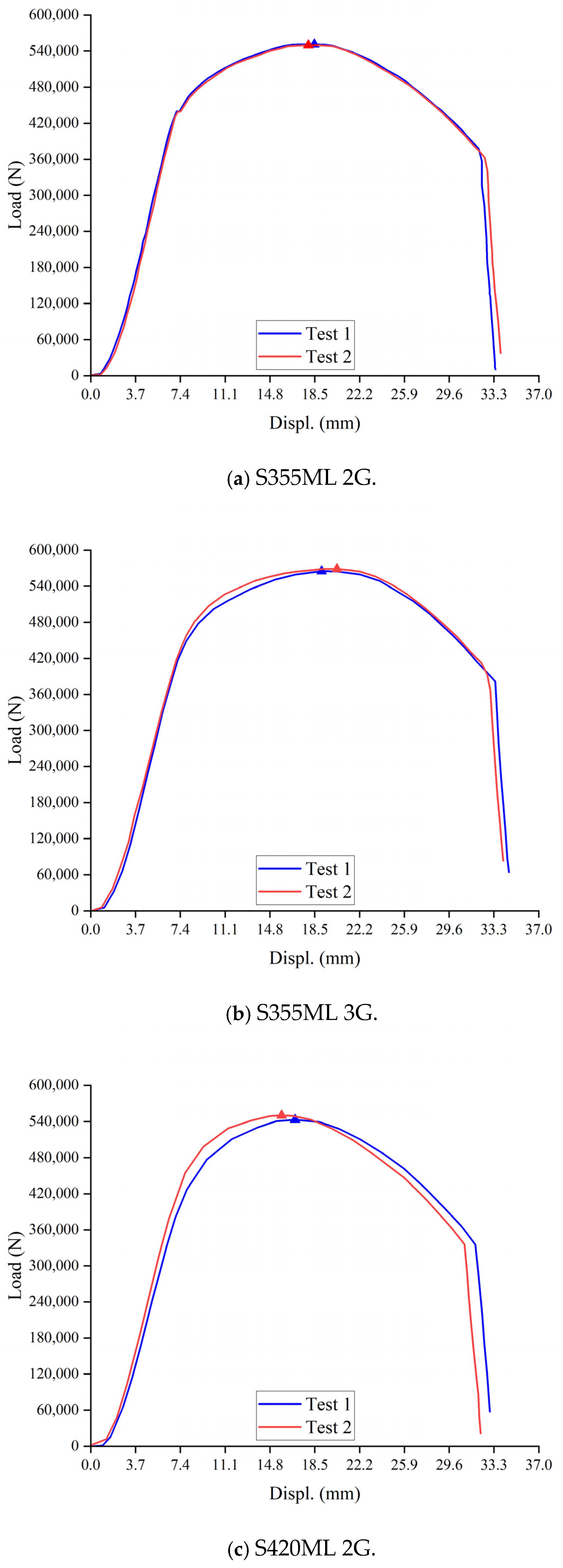
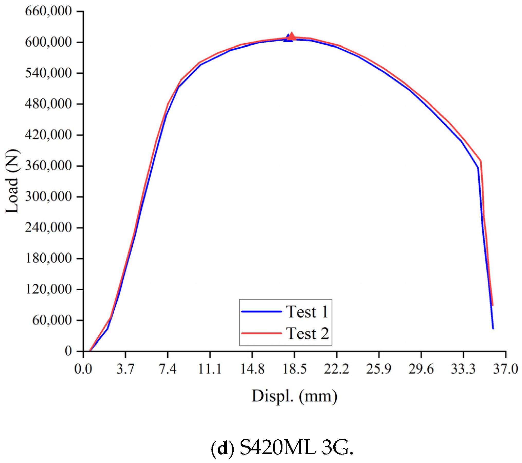
To review the tensile test results of the FCAW welded joints for both materials, the required standard conditions (EN 10025-4 [15]) and the tensile strength of the joints are presented in Table 4, while the load–displacement curves measured during the tests are illustrated in Figure 5.
As a result of welding, it was measured that both materials satisfied the base metal fracture and the strength criteria defined in the relevant standards for both 2G and 3G welding. Meanwhile, although the tensile strength of the S420ML 2G welded joint exceeded the standard requirement, it was measured at 552.2 MPa, which is lower than those of the other experimental conditions and the base metal strength specified in the mill certificate. To infer the cause of this strength reduction, the maximum angular distortion after the experiments was measured for each condition in this study, yielding results of 1.90° for S355ML 2G, 8.80° for S355ML 3G, 7.75° for S420ML 2G, and 6.70° for S420ML 3G. It is considered that the high heat input condition in the fill pass of the S420ML 2G welding induced stronger contraction compared to the S355ML 2G welding. Previous studies have reported cases where high heat input and angular distortion induced stress concentrations [45,46]. Similarly, in this study, it is believed that the high heat input conditions applied to the steel and the asymmetric groove geometry of the single-bevel during 2G welding could have affected the strength reduction. However, since a metallurgical analysis of the fracture surfaces of the specimens was not performed in this study, it is deemed necessary to additionally examine this aspect in future research. In addition, for the same material, even though the average heat input of the 3G welded joint was higher than that of the 2G welding, the strength was measured to be higher, which is judged to be because the V-groove geometry of 3G resulted in a more uniform stress distribution during the tensile test compared to the single-bevel groove geometry of 2G.

3.3. Impact Test of Low Temperature

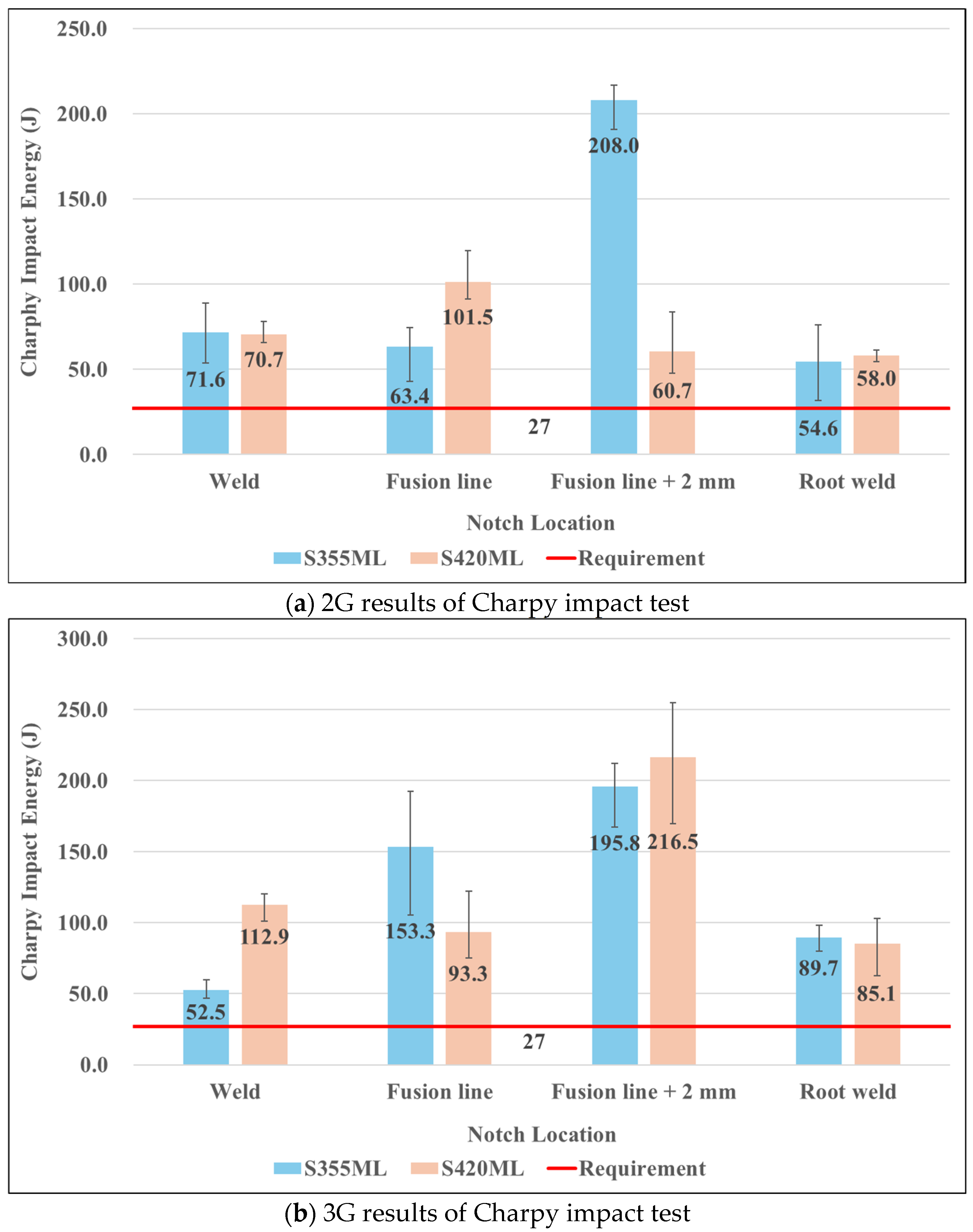
The results of the low-temperature impact test at −50 °C for each material are shown in Table 5, and this is illustrated in a graph in Figure 6. For both materials, the specified requirement at the corresponding temperature is 27 J or higher, and it was confirmed that the requirement was satisfied under all test conditions.
As a result of the tests, the impact toughness was measured to be relatively low in the root weld section for both materials, and it is judged that the repetition of fill and cap welding after the root weld pass induced continuous thermal exposure, which increased brittleness and weakened the impact toughness [47]. Furthermore, except for the 2G welding position of S420ML, the impact toughness at the Fusion line + 2 mm (F.L. + 2 mm) location was measured to be the highest across all other conditions. This distinct decrease in low-temperature impact toughness at the F.L. + 2 mm position of S420ML under the 2G condition exhibits a similar trend to previously documented cases in the high-strength steel welding literature [48,49]. In those references, such local degradation was reported to occur near the boundary between the coarse-grained HAZ (CGHAZ) and intercritical HAZ (ICHAZ), where multi-pass thermal cycles often promote the formation of coarse martensite–austenite (M-A) constituents. It should be noted that the primary objective of this study is focused on evaluating the macroscopic mechanical compliance under industrially specific welding procedures and verifying the technological differences regarding steel grades and positions; thus, high-resolution microstructural characterization remains outside the present investigative scope. However, considering that S420ML possesses higher microalloying contents (Nb and V) and carbon equivalent than S355ML, it can be presumably inferred that the relatively lower root pass heat input combined with the higher fill and cap pass inputs may have jointly altered the local transformation kinetics, potentially exerting a combined influence on the localized toughness boundaries. To establish explicit empirical evidence for these metallurgical mechanisms, a follow-up comparative study is currently planned to systematically investigate the effects of process-dependent heat input variations (i.e., relatively low heat input FCAW vs. high heat input SAW) on the microstructural evolution and localized embrittlement behavior of the identical companion steels.

3.4. Vickers Hardness Test Result

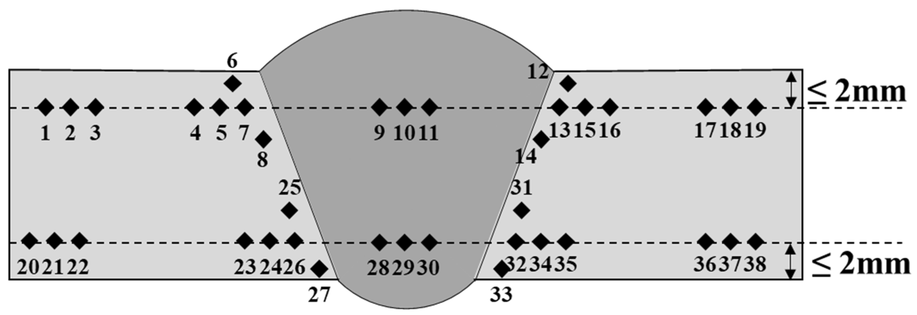
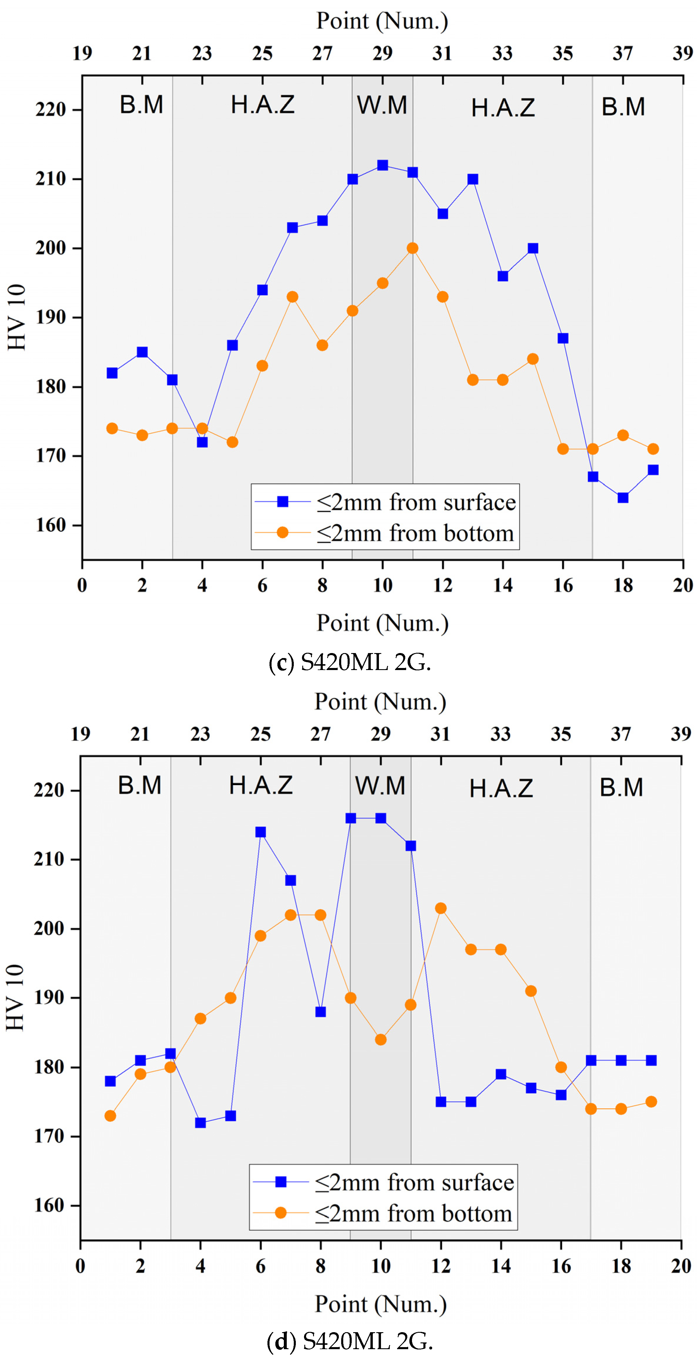
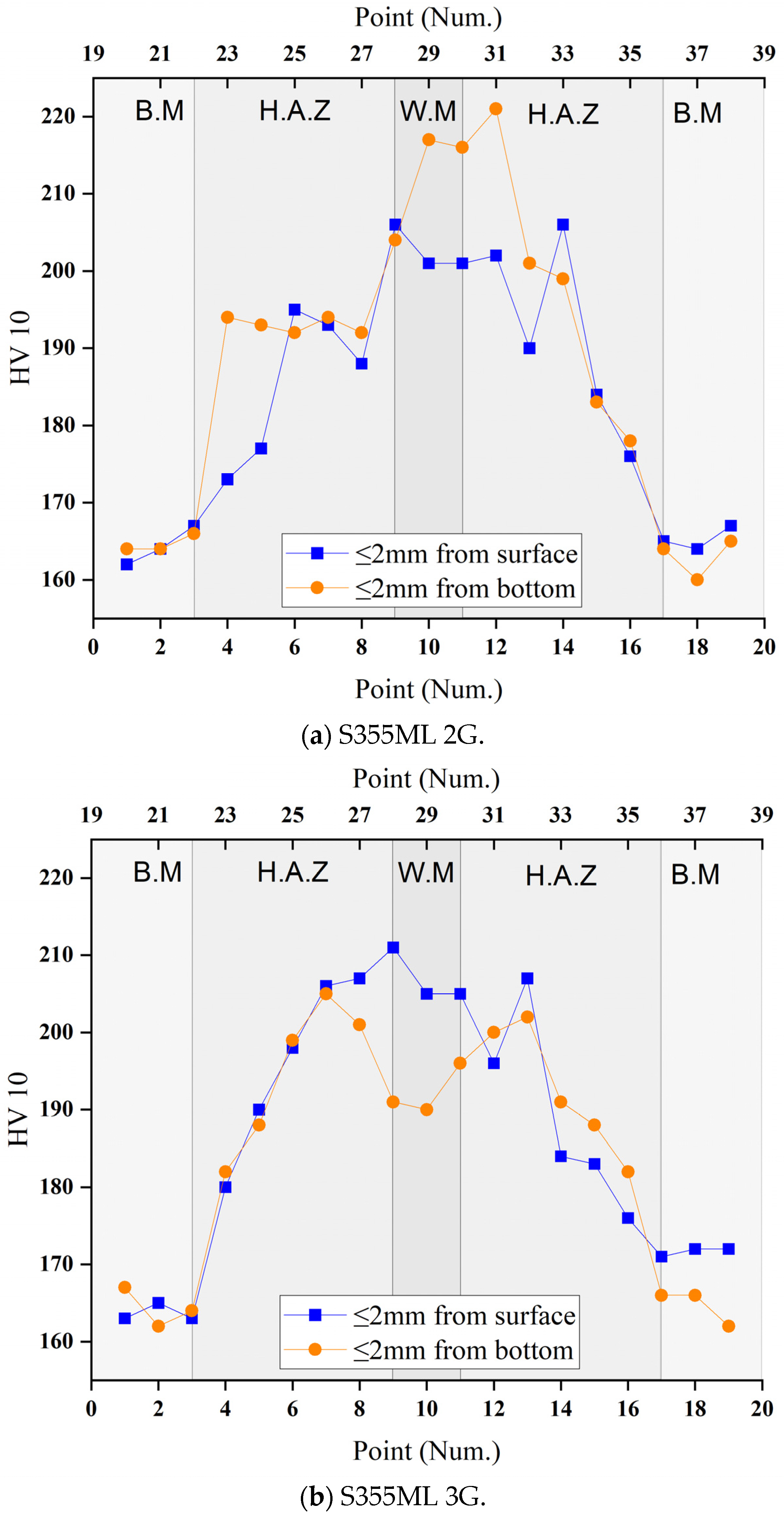
For each experimental condition, the Vickers hardness was measured at a total of 38 points as illustrated in Figure 7, which were categorized into the base metal (BM), heat-affected zone (HAZ), and weld metal (WM). For enhanced readability in the main text, the average values and standard deviations for each experiment and zone are summarized in Table 6, and the measured values for each location are graphically plotted in Figure 8. The points corresponding to the base metal are 1–3, 17–19, 20–22, and 36–38; the HAZ encompasses points 4–8, 12–16, 23–27, and 31–35; and the weld metal includes points 9–11 and 28–30.
Under all experimental conditions, the hardness of the BM was measured to be the lowest, and thereafter a trend of higher hardness was observed in the order of the HAZ and WM. When reviewing ISO 18265 and ASTM E140 [50,51], which are the standard conversion specifications for hardness and tensile strength of metallic materials, it is considered that fracture occurred in the base metal zone where the hardness was the lowest. In addition, for both the 2G and 3G welding conditions of S355ML, higher values were measured in the HAZ than for S420ML, which is judged to be due to the faster cooling rate resulting from the lower heat input compared to S420ML, thereby increasing the formation of fine grains and the solid solubility of microalloying elements. Meanwhile, to evaluate the hardness values of each weldment, the maximum allowable hardness for the weld zone of TMCP steels according to ISO 15614-1 [52], which was referenced, is a maximum of 380 HV10 when post-weld heat treatment is not performed, and it was confirmed that this value was satisfied in all the aforementioned zones.

4. Conclusions

In this study, 2G and 3G multi-pass FCAW experiments were performed on 40 mm thick S355ML and S420ML steel materials used for offshore wind substructures, respectively, and whether relevant standards (EN 10025-4 [15] and ISO 15614-1 [52]) were satisfied was verified to evaluate the mechanical performance and process-level suitability of the welded joints. To simulate actual industrial site conditions, relatively low heat input conditions were selected for 2G welding considering the groove geometry and the effect of gravity, whereas a high heat input was applied for 3G welding. The experimental results are summarized as follows:
  • Under all welding conditions, the tensile strength satisfied the EN 10025-4 [15] standard requirements, and base metal fracture occurred, thereby securing the integrity of the welded joints. Meanwhile, in the case of the 2G welding of S420ML, a tensile strength lower than that of the base metal was measured. Although this reduction in strength could potentially be attributed to the large angular distortion induced by high heat input welding and the stress concentration arising from the single-bevel groove geometry, further verification through future studies is required.
  • As a result of the low-temperature impact tests, all zones exceeded the standard requirement of 27 J or higher. Meanwhile, the impact toughness was measured to be relatively low in the root weld section, which is judged to be because the repetition of fill and cap welding after the root weld pass induced continuous thermal exposure, thereby increasing brittleness and weakening the impact toughness.
  • As a result of the hardness measurements, a distinct hardness gradient of weld metal (WM, 200–208 HV10) > heat-affected zone (HAZ, 189–193 HV10) > base metal (164–178 HV10) was exhibited under all conditions, confirming the formation of a sound welded joint. In addition, all zones were measured to be below 380 HV10, which is the maximum allowable hardness of ISO 15614-1 [52].
  • The experimental results of this study demonstrate that the proposed welding parameters meet all relevant industry standards, and it is believed that this can provide a basic welding engineering guide for thick structural steel used in large-scale offshore wind power projects, based on welding position and improved geometry. Furthermore, these steel grades and welding methods are mainly applied to the main supports and braces of heavy-section monopile substructures and jacket-type offshore wind power foundations.
  • This study performed multi-pass FCAW on heavy-section TMCP steels, which are increasingly thickened due to the expanding scale of offshore wind substructures, and successfully validated the mechanical compliance and suitability of the welding procedures against industrial standards. On the other hand, since offshore wind substructures are fatigue-sensitive and corrosion-exposed systems, future integrity evaluations under varying heat inputs will actively consider additional assessments including fatigue life, CTOD, residual stress, and corrosion fatigue to more comprehensively secure long-term structural integrity.

Author Contributions

Conceptualization, E.H.; methodology, Y.K.; software, Y.K.; validation, M.Y.; formal analysis, E.H. and M.Y.; investigation, Y.K.; resources, J.K.; data curation, E.H. and Y.K.; writing—original draft preparation, E.H. and M.Y.; writing—review and editing, J.K.; visualization, E.H. and M.Y.; supervision, J.K.; project administration, J.K.; funding acquisition, J.K. All authors have read and agreed to the published version of the manuscript.

Funding

This study was supported by the Ministry of Trade, Industry and Energy (MOTIE, Republic of Korea) through the New and Renewable Energy Core Technology Development Program “Development of manufacturing technology using automated production system for wind turbine support structures (RS-2024-00512715)” and the Korea Institute of Industrial Technology as “Development of a remote manufacturing system for high-risk, high-difficulty pipe production processes (KITECH-EH-26-0011)”.

Data Availability Statement

The data presented in this study are available within the article and raw data are not publicly available due to commercial restrictions.

Conflicts of Interest

The authors declare no conflicts of interest.

Abbreviations

The following abbreviations are used in this manuscript:
TMCPThermo-mechanical control process
FCAWFlux-cored arc welding
SAWSubmerged arc welding
EGWElectro gas welding
EBWElectron beam welding
LAHWLaser-arc hybrid welding
GMAWGas metal arc welding
BMBase metal
HAZHeat affected zone
WMWeld metal
ICHAZInter-critical heat affected zone
CGHAZCoarse grain heat affected zone
M-AMartensite-austenite

References

  1. Fernández-Guillamón, A.; Das, K.; Cutululis, N.A.; Molina-García, Á. Offshore Wind Power Integration into Future Power Systems: Overview and Trends. J. Mar. Sci. Eng. 2019, 7, 399. [Google Scholar] [CrossRef] [Scilit]
  2. Bilgili, M.; Alphan, H. Global growth in offshore wind turbine technology. Clean Technol. Environ. Policy 2022, 24, 2215–2227. [Google Scholar] [CrossRef] [Scilit]
  3. Soares-Ramos, E.P.P.; de Oliveira-Assis, L.; Sarrias-Mena, R.; Fernández-Ramírez, L.M. Current status and future trends of offshore wind power in Europe. Energy 2020, 202, 117787. [Google Scholar] [CrossRef] [Scilit]
  4. Zhou, B.; Zhang, Z.; Li, G.; Yang, D.; Santos, M. Review of Key Technologies for Offshore Floating Wind Power Generation. Energies 2023, 16, 710. [Google Scholar] [CrossRef] [Scilit]
  5. Su, X.; Wang, X.; Xu, W.; Yuan, L.; Xiong, C.; Chen, J. Offshore Wind Power: Progress of the Edge Tool, Which Can Promote Sustainable Energy Development. Sustainability 2024, 16, 7810. [Google Scholar] [CrossRef] [Scilit]
  6. Ali, H.; Al-Esbe, I.; Alwan, H.M. A review of offshore wind turbines: Global added capacity, monopile structure foundations stresses and deflection. Period. Eng. Nat. Sci. (PEN) 2021, 9, 712–731. [Google Scholar] [CrossRef] [Scilit]
  7. George, C.J.; Cherian, L.D.; Kamal, F. Installation of Monopile Substructures on Offshore Wind Farms—A Case Study. In Proceedings of the Offshore Technology Conference Asia, Kuala Lumpur, Malaysia, 31 March–2 April 2026. [Google Scholar]
  8. McWilliam, M.K.; Natarajan, A.; Pollini, N.; Dykes, K.; Barter, G.E. Conceptual monopile and tower sizing for the IEA Wind Task 37 Borssele reference wind farm. J. Phys. Conf. Ser. 2021, 2018, 012025. [Google Scholar] [CrossRef] [Scilit]
  9. Scholl, S.; Schütz, J.; Lenhard, S.; Lehnert, T.; Staudt, T.; Schütz, W. Development of Heavy Plates for High-Energy Welding of Monopiles for the Construction of Offshore Wind Energy Plants. In RDPS 2024 Proceedings; Association for Iron & Steel Technology (AIST): Warrendale, PA, USA, 2024. [Google Scholar] [CrossRef] [Scilit]
  10. Igwemezie, V.; Mehmanparast, A.; Kolios, A. Current trend in offshore wind energy sector and material requirements for fatigue resistance improvement in large wind turbine support structures—A review. Renew. Sustain. Energy Rev. 2019, 101, 181–196. [Google Scholar] [CrossRef] [Scilit]
  11. Adedipe, O.; Brennan, F.; Kolios, A. Review of corrosion fatigue in offshore structures: Present status and challenges in the offshore wind sector. Renew. Sustain. Energy Rev. 2016, 61, 141–154. [Google Scholar] [CrossRef] [Scilit]
  12. Li, Y.; Zhang, Y.; Wang, W.; Li, X.; Wang, B. Influence of Corrosion Damage on Fatigue Limit Capacities of Offshore Wind Turbine Substructure. J. Mar. Sci. Eng. 2022, 10, 1011. [Google Scholar] [CrossRef] [Scilit]
  13. Igwemezie, V.; Mehmanparast, A.; Kolios, A. Materials selection for XL wind turbine support structures: A corrosion-fatigue perspective. Mar. Struct. 2018, 61, 381–397. [Google Scholar] [CrossRef] [Scilit]
  14. Igwemezie, V.; Mehmanparast, A. Waveform and frequency effects on corrosion-fatigue crack growth behaviour in modern marine steels. Int. J. Fatigue 2020, 134, 105484. [Google Scholar] [CrossRef] [Scilit]
  15. EN 10025-4; Hot Rolled Products of Structural Steels—Part 4: Technical Delivery Conditions for Thermomechanical Rolled Weldable Fine Grain Structural Steels. European Committee for Standardization: Brussels, Belgium, 2019.
  16. EN 10225; Weldable Structural Steels for Fixed Offshore Structures—Technical Delivery Conditions. European Committee for standardization: Brussels, Belgium, 2019.
  17. NORSOK M-120; Material Data Sheets for Structural Steel. Standards Norway: Lysaker, Norway, 2021.
  18. DNV-OS-B101; Metallic Materials. DNG GL: Hovik, Norway, 2021.
  19. Ji, C.; Choi, C.Y.; Nam, D.-G.; Kim, H.C.; Jang, J.H.; Kim, K.H.; Park, Y.-D. Evaluation on Mechanical Properties with Welding Processes for Off Shore Wind Tower Application. J. Weld. Join. 2014, 32, 15–21. [Google Scholar] [CrossRef] [Scilit]
  20. Okenyi, V.; Afazov, S.; Mansfield, N.; Balakrishnan, J.; Kyffin, W.; Siegkas, P.; Marrocco, T.; Bodaghi, M. Submerged Arc Welding of S355G10+M Steel: Analyzing Strength, Distortion, Residual Stresses, and Fatigue for Offshore Wind Applications. Fatigue Fract. Eng. Mater. Struct. 2025, 48, 3859–3878. [Google Scholar] [CrossRef] [Scilit]
  21. Kim, Y.S.; Kil, S.-C. High efficient welding technology of the offshore wind power plants. J. Weld. Join. 2015, 33, 4–11. [Google Scholar] [CrossRef] [Scilit]
  22. Ren, R.; Feng, M.; Lian, G.; Peng, S.; Chen, J.; Chen, C. Study on the Influence of Welding Sequence on the Mechanical Properties and Microstructure of Flange Circumferential Welded Joints in Large-Capacity Offshore Wind Power Towers. Int. J. Precis. Eng. Manuf. 2026, 27, 1213–1233. [Google Scholar] [CrossRef] [Scilit]
  23. Choi, D.; Lee, H.; Cho, S.-K.; Kim, H.C.; Hyun, S.-K.; Shin, S.Y. Microstructure and Charpy Impact Properties of FCAW and SAW Heat Affected Zones of 100 mm Thick Steel Plate for Offshore Platforms. Met. Mater. Int. 2020, 26, 867–881. [Google Scholar] [CrossRef] [Scilit]
  24. Gáspár, M.; Sisodia, R.; Tervo, H.; Javaheri, V.; Kaijalainen, A. Challenges and opportunities in the arc welding of offshore steels. In Proceedings of the 76th IIW Annual Assembly and International Conference on Welding and Joining, Singapore, 16–21 July 2023. [Google Scholar]
  25. Li, Y.; Li, Y.; Chang, J. A Study on the Impact Toughness of the Simulated Heat-Affected Zone in Multi-Layer and Multi-Pass Welds of 1000 MPa Grade Steel for Hydroelectric Applications. Metals 2024, 14, 1455. [Google Scholar] [CrossRef] [Scilit]
  26. Gáspár, M.; Kovács, J.; Sainio, J.; Tervo, H.; Javaheri, V.; Kaijalainen, A. Physical simulation-based analysis of multipass welding in S500 shipbuilding steel. Weld. World 2025, 69, 825–836. [Google Scholar] [CrossRef] [Scilit]
  27. Bai, F.; Ding, H.; Tong, L.; Pan, L.; Wang, L. Microstructural Changes and Impact Toughness of Fill Pass in X80 Steel Weld Metal. Metals 2019, 9, 898. [Google Scholar] [CrossRef] [Scilit]
  28. Mehmanparast, A.; Taylor, J.; Brennan, F.; Tavares, I. Experimental investigation of mechanical and fracture properties of offshore wind monopile weldments: SLIC interlaboratory test results. Fatigue Fract. Eng. Mater. Struct. 2018, 41, 2485–2501. [Google Scholar] [CrossRef] [Scilit]
  29. Reisgen, U.; Olschok, S.; Evers, T. Development of a robust welding process for electron beam welding of thick plates for construction of offshore wind turbines. Mater. Werkst. 2024, 55, 900–909. [Google Scholar] [CrossRef] [Scilit]
  30. Gook, S.; Biegler, M.; Gumenyuk, A.; Rethmeier, M. Integration of hybrid Laser-Arc and narrow gap submerged arc welding for cost-effective joining of 80 mm thick S355ML steel plates. Opt. Laser Technol. 2026, 197, 114796. [Google Scholar] [CrossRef] [Scilit]
  31. Bunaziv, I.; Ren, X.; Olden, V. A comparative study of laser-arc hybrid welding with arc welding for fabrication of offshore substructures. J. Phys. Conf. Ser. 2023, 2626, 012033. [Google Scholar] [CrossRef] [Scilit]
  32. Wang, X.; Wang, X.; Xie, Z.; Li, L.; Yang, Y.; Zhang, G.; Liu, Z.; Shang, C. Segregation effects in a high-strength wind power steel: Microstructure, mechanical properties, and hydrogen embrittlement sensitivity of base metal and simulated HAZ. J. Mater. Res. Technol. 2025, 35, 6361–6371. [Google Scholar] [CrossRef] [Scilit]
  33. De Brito Ferreira, C.; Campanelli, L.C.; De Andrade Mendes Filho, A.; Dalmonico, G.M.L.; Reis, D. The Influence of Niobium Addition on the Mechanical Properties and Microstructure of High-Strength Low-Alloy Steel Processed Through a Conventional Rolling Mill. Mater. Res. 2025, 28, e20250447. [Google Scholar] [CrossRef] [Scilit]
  34. Wang, F.; Zhang, Z.; Xiao, G.; Zou, D. Effects of Vanadium and Niobium on the Mechanical Properties and High-Temperature Oxidation Behavior of Austenitic Stainless Steels. Metals 2025, 15, 347. [Google Scholar] [CrossRef] [Scilit]
  35. Jansto, S.G. The Integration of Process and Product Metallurgy in Niobium Bearing Steels. Metals 2018, 8, 671. [Google Scholar] [CrossRef] [Scilit]
  36. AWS A5.29; Specification for Low-Alloy Steel Electrodes for Flux Cored Arc Welding. American Welding Society: Miami, FL, USA, 2018.
  37. Odebiyi, O.S.; Adedayo, S.M.; Tunji, L.A.; Onuorah, M.O. A review of weldability of carbon steel in arc-based welding processes. Cogent Eng. 2019, 6, 1609180. [Google Scholar] [CrossRef] [Scilit]
  38. ISO 17639:2022; Destructive Tests on Welds in Metallic Materials—Macroscopic and Microscopic Examination of Welds. International Organization for Standardization: Geneva, Switzerland, 2022.
  39. ISO 4136:2022; Destructive Tests on Welds in Metallic Materials—Transverse Tensile Test. International Organization for Standardization: Geneva, Switzerland, 2022.
  40. ISO 148-1:2016; Metallic Materials—Charpy Pendulum Impact Test—Part 1: Test Method. International Organization for Standardization: Geneva, Switzerland, 2016.
  41. ISO 9015-1:2001; Destructive Tests on Welds in Metallic Materials—Hardness Testing—Part 1: Hardness Test on Arc Welded Joints. International Organization for Standardization: Geneva, Switzerland, 2001.
  42. ISO 6507-1:2018; Metallic Materials—Vickers Hardness Test—Part 1: Test Method. International Organization for Standardization: Geneva, Switzerland, 2018.
  43. ISO 17640:2018; Non-Destructive Testing of Welds—Ultrasonic Testing—Techniques, Testing Levels, and Assessment. International Organization for Standardization: Geneva, Switzerland, 2018.
  44. ISO 11666:2018; Non-Destructive Testing of Welds—Ultrasonic Testing—Acceptance Levels. International Organization for Standardization: Geneva, Switzerland, 2018.
  45. Peng, X.; Zhang, H.; Qiao, Y.; Sun, S.; Tu, D. Comparisons of microstructure and mechanical properties of MAG joints welded under 2G and 3G conditions. Mater. Res. Express 2024, 11, 066510. [Google Scholar] [CrossRef] [Scilit]
  46. Zhou, W.; Dong, P. An analytical method for consistent treatment of axial and angular misalignments in fatigue evaluation of welded joints. Thin-Walled Struct. 2022, 173, 109003. [Google Scholar] [CrossRef] [Scilit]
  47. Zhang, B.; Mu, W.; Liu, H.; Xie, G.; Cai, Y. Microstructure evolution of weld root in dissimilar weld metal in S690QL high-strength steel under multiple welding thermal cycles. J. Mater. Sci. 2023, 58, 10699–10715. [Google Scholar] [CrossRef] [Scilit]
  48. Jia, S.-j.; Ma, Q.-l.; Hou, Y.; Li, B.; Zhang, H.-s.; Liu, Q.-y. Changes in microstructure and properties of weld heat-affected zone of high-strength low-alloy steel. J. Iron Steel Res. Int. 2024, 31, 2041–2052. [Google Scholar] [CrossRef] [Scilit]
  49. Lahtinen, T.; Vilaça, P.; Peura, P.; Mehtonen, S. MAG Welding Tests of Modern High Strength Steels with Minimum Yield Strength of 700 MPa. Appl. Sci. 2019, 9, 1031. [Google Scholar] [CrossRef] [Scilit]
  50. ISO 18265; Metallic Materials-Conversion of Hardness Values. International Organization for Standardization: Geneva, Switzerland, 2013.
  51. ASTM E140; Standard Hardness Conversion Tables for Metals Relationship Among Brineel Hardness, Vickers Hardness, Rockwell Hardness. ASTM International: West Conshohocken, PA, USA, 2020.
  52. ISO 15614-1; Specification and Qualification of Welding Procedures for Metallic Materials—Welding Procedure Test—Part 1: Arc and Gas Welding of Steels and Arc Welding of Nickel and Nickel Alloys. International Organization for Standardization: Geneva, Switzerland, 2017.
Figure 1. Dimension of base metal (FCAW).
Metals 16 00800 g001
Figure 2. Joint detail of FCAW.
Metals 16 00800 g002
Figure 3. Dimension of tensile test specimen.
Metals 16 00800 g003
Figure 4. Results of cross-section observation.
Metals 16 00800 g004
Figure 5. Results of tensile test (load–displacement graph).
Metals 16 00800 g005aMetals 16 00800 g005b
Figure 6. Results of Charpy impact test.
Metals 16 00800 g006
Figure 7. Measurement points of Vickers hardness test.
Metals 16 00800 g007
Figure 8. Results of Vickers hardness test (graph).
Metals 16 00800 g008aMetals 16 00800 g008b
Table 1. Chemical composition (wt.%) (a) and mechanical properties (b) of base metal.
(a)
ComponentS355MLS420ML
C0.080.09
Si0.280.3
Mn1.521.5
P0.0170.016
S0.0030.003
Cr0.020.03
Ni0.010.01
Cu0.010.04
Mo0.003Tr
Nb0.0190.023
Ti0.0170.015
V0.0020.006
Al0.0420.031
N0.00380.0031
(b)
ClassificationPropertiesS355MLS420ML
Requirement
(EN10025-4)
Tensile strength, MPa470–630540–720
Impact energy, J (−50 °C)2727
Base metalTensile strength, MPa549584
Impact energy, J (−50 °C)306293
Table 2. Chemical composition (wt.%) (a) and mechanical properties (b) of filler metal.
(a)
ComponentE81T1-K2C H4
C0.03
Si0.40
Mn1.26
P0.007
S0.006
Cr0.03
Ni1.46
Mo0.01
V0.02
(b)
PropertiesE81T1-K2C H4
Tensile strength, MPa580
Impact energy, J (−60 °C)64
Table 3. Welding condition of FCAW. (a) S355ML steel; (b) S420ML steel.
(a)
PositionPass (Number of Pass)Current
(A)
Voltage
(V)
Speed
(mm/min)
Heat Input
(kJ/mm)
Max. Inter-Pass Temperature (°C)
2GRoot
(1)
240–26024–26150–2201.26–2.16-
Fill
(2~22)
220–24021–24210–3000.77–1.32225
Cap
(23~28)
220–24021–24220–2900.76–1.26212
3GRoot
(1)
220–24022–24100–1401.66–2.76-
Fill
(2~17)
220–25022–24210–2700.86–1.37221
Cap
(18~20)
200–23022–24200–2600.81–1.32210
(b)
PositionPass (Number of Pass)Current
(A)
Voltage
(V)
Speed
(mm/min)
Heat Input
(kJ/mm)
Max. Inter-Pass Temperature (°C)
2GRoot
(1)
220–25022–24150–2001.16–1.92-
Fill
(2~21)
230–26023–26200–2600.98–1.62242
Cap
(22~27)
230–25023–26190–2500.76–1.26207
3GRoot
(1)
230–25024–26110–1501.66–2.76-
Fill
(2~17)
230–25024–26190–2601.02–1.52213
Cap
(18~20)
230–25025–27200–2701.02–1.62218
Table 4. Results of tensile test.
ClassificationS355ML (40 mm)S420ML (40 mm)
Requirement (EN10025-4), MPa470~630520~680
Weld metal
(2G)
T1, MPa567.3550.3
T2, MPa567.9554.1
Average, MPa567.6552.2
Fracture locationBase metalBase metal
Weld metal
(3G)
T1, MPa570.0596.9
T2, MPa572.3599.9
Average, MPa571.2598.4
Fracture locationBase metalBase metal
Table 5. Results of impact test at −50 °C.
Notch Location/DirectionValues (J)
S355ML (40 mm)S420ML (40 mm)
Test No.123Avg.123Avg.
2GWeld53.772.089.071.665.978.068.270.7
Fusion line74.572.942.963.491.5119.693.3101.5
Fusion line + 2 mm190.8216.4216.8208.083.750.847.760.7
Root weld31.876.355.654.654.558.061.558.0
3GWeld51.359.646.752.5117.3120.2101.1112.9
Fusion line105.5161.9192.5153.375.4122.282.493.3
Fusion line + 2 mm207.9167.4212.0195.8169.7224.9254.8216.5
Root weld98.390.780.089.762.689.8103.085.1
Table 6. Results of Vickers hardness test.
LocationPointValue (Avg./Standard Deviation)
S355ML 2GS355ML 3GS420ML 2GS420ML 3G
BM1~3164/2.5164/1.2183/2.1180/2.1
17~19165/1.5172/0.6166/2.1181/0.0
20~22165/1.2164/2.5174/0.6177/3.8
36~38165/2.6165/2.3172/1.2174/0.6
HAZ4~8185/9.8196/11.4192/13.3191/19.2
12~16192/12.4189/12.3200/8.8176/1.7
23~27193/1.0195/9.6182/8.7196/7.0
31~35196/17.0193/8.4182/7.9194/8.7
WM9~11203/2.9207/3.5211/1.0215/2.3
28~30212/7.2192/3.2195/4.5188/3.2
Disclaimer/Publisher’s Note: The statements, opinions and data contained in all publications are solely those of the individual author(s) and contributor(s) and not of MDPI and/or the editor(s). MDPI and/or the editor(s) disclaim responsibility for any injury to people or property resulting from any ideas, methods, instructions or products referred to in the content.